
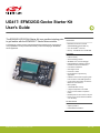
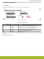
UG417: EFM32GG Gecko Starter Kit
User's Guide
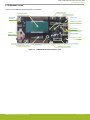
The EFM32GG-STK3700A Starter Kit is an excellent starting point
to get familiar with the EFM32GG™ Gecko Microcontroller.
The Starter Kit contains sensors and peripherals demonstrating some of the Gecko's
many capabilities. The kit provides all necessary tools for developing an EFM32GG
Gecko application.
TARGET DEVICE
• EFM32GG Gecko Microcontroller
(EFM32GG990F1024G-E-BGA112)
•
CPU: 32-bit ARM
®
Cortex-M3
• Memory: 1024 kB flash and 128 kB RAM
KIT FEATURES
• USB connectivity
• Advanced Energy Monitor
• SEGGER J-Link on-board debugger
• Debug Multiplexer supporting external
hardware as well as on-board MCU
• User LEDs / Pushbuttons
• 8x20 segment LCD
• Inductive LC sensor
• Photo transistor for light sensing
applications
• USB Micro-AB connector supporting both
host and device mode USB applications
• 2 push buttons and 2 LEDs connected to
EFM32 for user interaction
• Backup battery
• 1 Gbit NAND flash memory
• 4-segment Capacitive Touch Slider
• 20-pin 2.54 mm header for expansion
boards
• Breakout pads for direct access to I/O pins
• Power sources include USB and CR2032
coin cell battery.
SOFTWARE SUPPORT
• Simplicity Studio™
• IAR Embedded Workbench
silabs.com
| Building a more connected world. Rev. 1.00

Table of Contents
1. Introduction ................................4
1.1 Description ...............................4
1.2 Features ................................4
1.3 Getting Started ..............................4
2. Kit Block Diagram .............................5
3. Kit Hardware Layout ............................6
4. Connectors ................................7
4.1 Breakout Pads ..............................7
4.2 Expansion Header .............................9
4.3 Debug Connector (DBG) ..........................11
4.4 Simplicity Connector ............................12
5. Power Supply and Reset ..........................13
5.1 MCU Power Selection ...........................13
5.2 Board Controller Power ...........................13
5.3 EFM32GG Reset .............................14
6. Peripherals ...............................15
6.1 Push Buttons and LEDs ...........................15
6.2 LCD .................................15
6.3 Capacitive Touch Slider ...........................16
6.4 LC Sensor ...............................16
6.5 Ambient Light Sensor............................17
6.6 USB Micro-AB Connector ..........................17
6.7 NAND Flash Memory ............................18
6.8 Opamp Footprint .............................19
6.9 Virtual COM Port .............................20
7. Advanced Energy Monitor .........................21
7.1 Usage .................................21
7.2 Theory of Operation ............................21
7.3 Accuracy and Performance ..........................21
8. On-Board Debugger ............................22
8.1 Debug Modes ..............................23
8.2 Debugging During Battery Operation ......................24
9. Kit Configuration and Upgrades .......................25
9.1 Firmware Upgrades ............................25
silabs.com
| Building a more connected world. Rev. 1.00 | 2

10. Schematics, Assembly Drawings, and BOM ..................26
11. Kit Revision History and Errata .......................27
11.1 Revision History .............................27
11.2 Errata ................................27
12. Document Revision History ........................28
silabs.com | Building a more connected world. Rev. 1.00 | 3

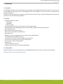
1. Introduction
1.1 Description
The EFM32GG-STK3700A is an excellent starting point to get familiar with the EFM32GG Gecko Microcontrollers. The kit contains sen-
sors and peripherals demonstrating some of the EFM32GG Gecko's many capabilities. The kit can also serve as a starting point for
application development.
In addition to supporting application development on the starter kit itself, the board is also a fully featured debugger and energy monitor-
ing tool that can be used with external applications.
1.2 Features
• EFM32GG Gecko Microcontroller
• 1024 kB Flash
• 128 kB RAM
• BGA112 package
• Advanced Energy Monitoring system for precise current and voltage tracking
• Integrated Segger J-Link USB debugger/emulator with the possiblity to debug external Silicon Labs devices
• 20 pin expansion header
• Breakout pads for easy access to I/O pins
• Power sources include USB and CR2032 battery
• 8x20 segment LCD
• USB Micro-AB connector supporting both host and device mode USB applications
• 1 Gbit parallell interface NAND flash memory
• 2 push buttons and 2 LEDs connected to EFM32 for user interaction
• LC tank circuit for inductive proximity sensing of metallic objects
• Photo transistor for light sensing applications
• Backup battery
• 4-segment capacitive touch slider
• Crystals for LFXO and HFXO: 32.768 kHz and 48.000 MHz.
1.3 Getting Started
Detailed instructions for how to get started with your new EFM32GG-STK3700A can be found on the Silicon Labs web pages:
https://www.silabs.com/mcu/32-bit/efm32-giant-gecko
UG417: EFM32GG Gecko Starter Kit User's Guide
Introduction
silabs.com | Building a more connected world. Rev. 1.00 | 4

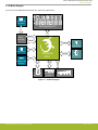
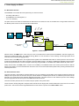
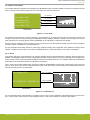
2. Kit Block Diagram
An overview of the EFM32GG Gecko Starter Kit is shown in the figure below.
LCD
8x20 Segment LCD
User Buttons
& LEDs
EXP Header
LC Sensor
LESENSE
LESENSE
GPIO
Board
Controller
USB Mini-B
Connector
DEBUG
Capacitive Touch Slider
ACMP
USB Micro-AB
Connector
Light Sensor
EFM32GG
MCU
USB
GPIO
1 Gbit NAND
Flash Memory
EBI
UART
Figure 2.1. Kit Block Diagram
UG417: EFM32GG Gecko Starter Kit User's Guide
Kit Block Diagram
silabs.com | Building a more connected world. Rev. 1.00 | 5

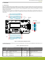
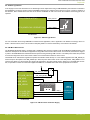
3. Kit Hardware Layout
The layout of the EFM32GG Gecko Starter Kit is shown below.
Debug USB
Connector
CR2032
Battery Holder
8x20 Segment LCD
Light Sensor
EFM32GG990 MCU
EXP Header
EFM32 Reset Button
User RGB LEDs
User Push Buttons
Power Source Select
Inductive LC Sensor
Capacitive Touch Slider
EFM32 USB Connector
Backup Battery
Simplicity Connector
NAND Flash Memory
Debug Connector
Figure 3.1. EFM32GG-STK3700A Hardware Layout
UG417: EFM32GG Gecko Starter Kit User's Guide
Kit Hardware Layout
silabs.com | Building a more connected world. Rev. 1.00 | 6

4. Connectors
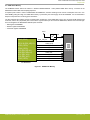
4.1 Breakout Pads
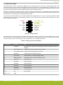
Most of the EFM32GG's GPIO pins are available on two pin header rows at the top and bottom edges of the board. These have a
standard 2.54 mm pitch, and pin headers can be soldered in if required. In addition to the I/O pins, connections to power rails and
ground are also provided. Note that some of the pins are used for kit peripherals or features, and may not be available for a custom
application without tradeoffs.
The figure below shows the pinout of the breakout pads, as well as the pinout of the EXP header on the right edge of the board. The
EXP header is further explained in the next section. The breakout pad connections are also printed in silk screen next to each pin for
easy reference.
GND
VMCU
PF2
PF1
PF0
NC
GND
PC7
PC6
PC5
PC4
PC3
PC2
PC1
PC0
3V3
GND
VMCU
PF9
PF8
NC
NC
GND
PE3
PE2
PE1
PE0
PB15
PA14
PA13
PA12
3V3
J101
J102
GND
5V
PD15
PD14
PD13
PD8
GND
PD7
PD6
PD5
PD4
PD3
PD2
PD1
PD0
GND
5V
PE15
PE14
PE13
PE12
GND
PE11
PE10
PE9
PE8
NC
PB11
PB10
PB9
3V33V3
PC0
PC3
PC4
PC5
GND
PB11
NC
PD7
5V
PD0
PD1
PD2
PD3
PD4
PD5
PD6
VMCU
3V3
Board ID SDA
Board ID SCL
EXP Header
Debug
Connector
Simplicity
Connector
Figure 4.1. Breakout Pads and Expansion Header
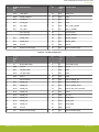
The table below shows the connections of each pin of the breakout pads. It also shows which kit peripherals or features that are con-
nected to the different pins.
Table 4.1. Bottom Row (J101) Pinout
Pin EFM32G
G I/O
pin
Shared feature Pin EFM32G
G I/O
pin
Shared feature
1 VMCU EFM32GG voltage domain 2 VMCU EFM32GG voltage domain
3 GND Ground 4 GND Ground
5 PA12 LCD_BCAP_P 6 PC0 EXP3
7 PA13 LCD_BCAP_N 8 PC1 NAND_ALE
UG417: EFM32GG Gecko Starter Kit User's Guide
Connectors
silabs.com | Building a more connected world. Rev. 1.00 | 7

Pin EFM32G
G I/O
pin
Shared feature Pin EFM32G
G I/O
pin
Shared feature
9 PA14 LCD_BEXT 10 PC2 NAND_CLE
11 PB15 NAND_PWR_EN 12 PC3 EXP5
13 PE0 VCOM_TX 14 PC4 EXP7
15 PE1 VCOM_RX 16 PC5 EXP9
17 PE2 UIF_LED0 18 PC6 LES_LIGHT_SENSE
19 PE3 UIF_LED1 20 PC7 LES_LC_SENSE
21 Not connected 22 Not connected
23 Not connected 24 PF0 DEBUG_SWCLK
25 PF8 NAND_WE# 26 PF1 DEBUG_SWDIO
27 PF9 NAND_RE# 28 PF2 DEBUG_SWO
29 GND Ground 30 GND Ground
31 3V3 Board controller supply 32 3V3 Board controller supply
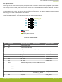
Table 4.2. Top Row (J102) Pinout
Pin EFM32G
G I/O
pin
Shared feature Pin EFM32G
G I/O
pin
Shared feature
1 5V Board USB voltage 2 5V Board USB voltage
3 GND Ground 4 GND Ground
5 PB9 UIF_BUTTON0 6 PD0 EXP4
7 PB10 UIF_BUTTON1 8 PD1 EXP6
9 PB11 EXP11 10 PD2 EXP8
11 Not Connected 12 PD3 EXP10, OPAMP_N2
13 PE8 NAND_IO0 14 PD4 EXP12, OPAMP_P2
15 PE9 NAND_IO1 16 PD5 EXP14, OPAMP_OUT2
17 PE10 NAND_IO2 18 PD6 EXP16, LES_LIGHT_EXCITE
19 PE11 NAND_IO3 20 PD7 EXP15
21 PE12 NAND_IO4 22 PD8 BU_VIN
23 PE13 NAND_IO5 24 PD13 NAND_WP#
25 PE14 NAND_IO6 26 PD14 NAND_CE#
27 PE15 NAND_IO7 28 PD15 NAND_R/B#
29 GND Ground 30 GND Ground
31 3V3 Board controller supply 32 3V3 Board controller supply
UG417: EFM32GG Gecko Starter Kit User's Guide
Connectors
silabs.com | Building a more connected world. Rev. 1.00 | 8

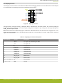
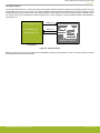
4.2 Expansion Header
On the right hand side of the board an angled 20 pin expansion header is provided to allow connection of peripherals or plugin boards.
The connector contains a number of I/O pins that can be used with most of the EFM32GG Gecko's features. Additionally, the VMCU,
3V3 and 5V power rails are also exported.
The connector follows a standard which ensures that commonly used peripherals such as an SPI, a UART and an I
2
C bus are available
on fixed locations in the connector. The rest of the pins are used for general purpose I/O. This allows the definition of expansion boards
that can plug into a number of different Silicon Labs starter kits.
The figure below shows the pin assignment of the expansion header for the EFM32GG Gecko Starter Kit. Because of limitations in the
number of available GPIO pins, some of the expansion header pins are shared with kit features.
12
4
8
6
10
3
5
9
7
12
13
14
11
1516
17
18
20 19
VMCU
PD0
PD1
PD2
PD3
PD4
PD5
PD6
5V
3V3
GND
PC0
PC3
PC4
PC5
PB11
NC
PD7
BOARD_ID_SDA
BOARD_ID_SCL
Reserved (Board Identification)
TARGET I/O Pin
Figure 4.2. Expansion Header
Table 4.3. EXP Header Pinout
Pin Connection EXP Header function Shared feature Peripheral mapping
20 3V3 Board controller supply
18 5V Board controller USB voltage
16 PD6 I2C_SDA LES_LIGHT_EXCITE I2C0_SDA #1
14 PD5 UART_RX OPAMP_OUT2 LEUART0_RX #0
12 PD4 UART_TX OPAMP_P2 LEUART0_TX #0
10 PD3 SPI_CS OPAMP_N2 USART1_CS #1
8 PD2 SPI_SCLK USART1_CLK #1
6 PD1 SPI_MISO USART1_RX #1
4 PD0 SPI_MOSI USART1_TX #1
2 VMCU EFM32GG voltage domain, included in AEM measurements.
19 BOARD_ID_SDA Connected to Board Controller for identification of add-on boards.
17 BOARD_ID_SCL Connected to Board Controller for identification of add-on boards.
15 PD7 I2C_SCL I2C0_SCL #1
13 NC Install R300 to connect to
PB12/DAC_LC_EXCITE
DAC0_OUT1
11 PB11 DAC_OUT DAC0_OUT0
UG417: EFM32GG Gecko Starter Kit User's Guide
Connectors
silabs.com | Building a more connected world. Rev. 1.00 | 9

Pin Connection EXP Header function Shared feature Peripheral mapping
9 PC5 GPIO
7 PC4 GPIO
5 PC3 GPIO
3 PC0 GPIO
1 GND Ground
UG417: EFM32GG Gecko Starter Kit User's Guide
Connectors
silabs.com | Building a more connected world. Rev. 1.00 | 10

4.3 Debug Connector (DBG)
The Debug Connector serves a dual purpose, depending on the "debug mode", which can be set up using Simplicity Studio. In the
"Debug IN" mode this connector allows an external debug emulator to be used with the on-board EFM32GG. In the "Debug OUT" mode
this connector allows the kit to be used as a debugger towards an external target. In the "Debug MCU" (default) mode this connector is
isolated from the debug interface of both the Board Controller and the on-board target device.
Because this connector is automatically switched to support the different operating modes, it is only available when the Board Controller
is powered (J-Link USB cable connected). If debug access to the target device is required when the Board Controller is unpowered, this
should be done by connecting directly to the appropriate breakout pins.
The pinout of the connector follows that of the standard ARM Cortex Debug+ETM 19-pin connector. The pinout is described in detail
below. Note that when using the on-board debugger to debug an mcu on an external board, JTAG and ETM functionality is only availa-
ble if the target device supports it.
1 2
4
8
6
10
5
9
12
13 14
11
15 16
17 18
2019
TMS / SWDIO / C2D
TCK / SWCLK / C2CK
TDO / SWO
TDI / C2Dps
TRACECLK
TRACED0
TRACED1
TRACED2
TRACED3
RESET / C2CKps
GND
NC
NC
GND
GND
GND
7
GND
VTARGET
Cable Detect
NC
3
Figure 4.3. Debug Connector
Note that the pin-out matches the pin-out of an ARM Cortex Debug+ETM connector, but these are not fully compatible as pin 7 is physi-
cally removed from the Cortex Debug+ETM connector. Some cables have a small plug that prevent them from being used when this pin
is present. If this is the case, remove the plug, or use a standard 2x10 1.27 mm straight cable instead.
Table 4.4. Debug Connector Pin Descriptions
Pin number(s) Function Note
1 VTARGET Target reference voltage. Used for shifting logical signal levels between target and
debugger.
2 TMS / SDWIO / C2D JTAG test mode select, Serial Wire data or C2 data
4 TCK / SWCLK / C2CK JTAG test clock, Serial Wire clock or C2 clock
6 TDO/SWO JTAG test data out or Serial Wire Output
8 TDI / C2Dps JTAG test data in, or C2D "pin sharing" function
10 RESET / C2CKps Target device reset, or C2CK "pin sharing" function
12 TRACECLK ETM Trace Clock
14 TRACED0 ETM Trace Data 0
16 TRACED1 ETM Trace Data 1
18 TRACED2 ETM Trace Data 2
20 TRACED3 ETM Trace Data 3
9 Cable detect Connect to ground
11, 13 NC Not connected
3, 5, 15, 17, 19 GND
UG417: EFM32GG Gecko Starter Kit User's Guide
Connectors
silabs.com | Building a more connected world. Rev. 1.00 | 11

4.4 Simplicity Connector
The Simplicity Connector featured on the Starter Kit enables advanced debugging features such as the AEM and the Virtual COM port
to be used towards an external target. The pinout is illustrated in the figure below.
VMCU
1
33V3
5
5V
15
GND
13
GND
11
GND
9
GND
7
GND
17
Board ID SCL
19
Board ID SDA
2
Virtual COM TX
4 Virtual COM RX
6 Virtual COM CTS
8
Virtual COM RTS
10
NC
12
NC
14
NC
16
NC
18
NC
20
NC
Figure 4.4. Simplicity Connector
The signal names in the figure and the pin description table are referenced from the board controller. This means that VCOM_TX
should be connected to the RX pin on the external target, VCOM_RX to the target's TX pin, VCOM_CTS to the target's RTS pin and
VCOM_RTS to the target's CTS pin.
Note: Current drawn from the VMCU voltage pin is included in the AEM measurements, while the 3V3 and 5V voltage pins are not. To
monitor the current consumption of an external target with the AEM, put the on-board MCU in its lowest energy mode to minimize its
impact on the measurements.
Table 4.5. Simplicity Connector Pin Descriptions
Pin number(s) Function Description
1 VMCU 3.3 V power rail, monitored by the AEM
3 3V3 3.3 V power rail
5 5V 5 V power rail
2 VCOM_TX Virtual COM Tx
4 VCOM_RX Virtual COM Rx
6 VCOM_CTS Virtual COM CTS
8 VCOM_RTS Virtual COM RTS
17 EXT_ID_SCL Board ID SCL
19 EXT_ID_SDA Board ID SDA
10, 12, 14, 16, 18, 20 NC Not connected
7, 9, 11, 13, 15 GND Ground
UG417: EFM32GG Gecko Starter Kit User's Guide
Connectors
silabs.com | Building a more connected world. Rev. 1.00 | 12

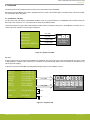
5. Power Supply and Reset
5.1 MCU Power Selection
The EFM32GG on the Starter Kit can be powered by one of these sources:
• The debug USB cable; or
• the EFM32GG's own USB regulator; or
• a 3 V coin cell battery.
The power source for the MCU is selected with the slide switch in the lower left corner of the Starter Kit. The figure below shows how
the different power sources can be selected with the slide switch.
3.3 V
VMCU
AEM
USB
BAT
USB Mini-B
Connector
5 V
3V Lithium Battery
(CR2032)
EFM32
MCU
USB_VREGI
(5V)
USB_VREGO
(3.3V)
.
BAT
U
S
B
AEM
LDO
USB Micro-AB
Connector
Advanced
Energy
Monitor
SENSE
VBUS
Figure 5.1. Power Switch
With the switch in the AEM position, a low-noise 3.3 V LDO on the Starter Kit is used to power the EFM32GG. This LDO is again pow-
ered from the debug USB cable. The Advanced Energy Monitor is now connected in series, allowing accurate high-speed current
measurements and energy debugging/profiling.
With the switch in the USB position, the integrated linear regulator in the EFM32GG Gecko MCU is used to power the rest of the chip
as well as the USB PHY with the cable connected to the target USB connector. This allows a USB device application where the MCU
acts as a bus powered device. Current consumption monitoring using the AEM is not available when USB is selected as power source.
Finally, with the switch in the BAT position, a 20 mm coin cell battery in the CR2032 socket can be used to power the device. With the
switch in this position no current measurements are active. This is the recommended switch position when powering the MCU with an
external power source.
5.2 Board Controller Power
The board controller is responsible for important features, such as the debugger and the AEM, and is powered exclusively through the
USB port in the top left corner of the board. This part of the kit resides on a separate power domain, so a different power source can be
selected for the target device while retaining debugging functionality. This power domain is also isolated to prevent current leakage
from the target power domain when power to the Board Controller is removed.
The board controller power domain is not influenced by the position of the power switch.
The kit has been carefully designed to keep the board controller and the target power domains isolated from each other as one of them
powers down. This ensures that the target EFM32GG device will continue to operate in the USB and BAT modes.
UG417: EFM32GG Gecko Starter Kit User's Guide
Power Supply and Reset
silabs.com | Building a more connected world. Rev. 1.00 | 13

5.3 EFM32GG Reset
The EFM32GG MCU can be reset by a few different sources:
• A user pressing the RESET button
• The on-board debugger pulling the #RESET pin low
• An external debugger pulling the #RESET pin low
In addition to the reset sources mentioned above, a reset to the EFM32GG will also be issued during board controller boot-up. This
means that removing power to the board controller (unplugging the J-Link USB cable) will not generate a reset, but plugging the cable
back in will, as the board controller boots up.
UG417: EFM32GG Gecko Starter Kit User's Guide
Power Supply and Reset
silabs.com | Building a more connected world. Rev. 1.00 | 14

6. Peripherals
The starter kit has a set of peripherals that showcase some of the features of the EFM32GG.
Be aware that most EFM32GG I/O routed to peripherals are also routed to the breakout pads or the EXP header. This must be taken
into consideration when using these.
6.1 Push Buttons and LEDs
The kit has two user push buttons marked BTN0 and BTN1. They are connected directly to the EFM32GG and are debounced by RC
filters with a time constant of 1 ms. The buttons are connected to pins PB9 and PB10.
The kit also features two yellow LEDs marked LED0 and LED1 that are controlled by GPIO pins on the EFM32GG. The LEDs are con-
nected to pins PE2 and PE3 in an active-high configuration.
PE3 (GPIO)
User Buttons
& LEDs
UIF_LED0
UIF_LED1
PB9 (GPIO)
PB10 (GPIO_EM4WU2)
PE2 (GPIO)
EFM32GG
UIF_BUTTON0
UIF_BUTTON1
Figure 6.1. Buttons and LEDs
6.2 LCD
A 28-pin segment LCD is connected to the EFM32's LCD peripheral. The LCD has 8 common lines and 20 segment lines, giving a total
of 160 segments in octaplex mode. These lines are not shared on the breakout pads. Refer to the kit schematic for information on sig-
nals to segments mapping.
A capacitor connected to the EFM32 LCD peripheral's voltage boost pin is also available on the kit.
EFM32GG
LCD_SEG[39:35]
LCD_SEG[31:28]
LCD_BCAP[N, P]
LCD_SEG[34:32]
PA[11:7]
PB[2:0]
PD[12:9]
PA[13:12]
PA[15]
PB[6:3]
PA[6:0]
PE[7:4]
LCD_SEG[12]
LCD_SEG[19:13]
LCD_COM[7:4]
LCD_COM[3:0]
LCD_SEG
LCD_COM
PA14
LCD_BEXT
1 uF
8x20 Segment LCD
22 nF
Figure 6.2. Segment LCD
UG417: EFM32GG Gecko Starter Kit User's Guide
Peripherals
silabs.com | Building a more connected world. Rev. 1.00 | 15

6.3 Capacitive Touch Slider
A touch slider utilizing the capacitive touch capability of the EFM32GG's analog comparator (ACMP) is located on the bottom side of the
board. It consists of four interleaved pads which are connected to PC8, PC9, PC10 and PC11.
PC8 (ACMP1 CH0)
PC9 (ACMP1 CH1)
UIF_TOUCH0
UIF_TOUCH1
EFM32GG
Capacitive Touch Slider
UIF_TOUCH2
UIF_TOUCH3
PC10 (ACMP1 CH2)
PC11 (ACMP1 CH3)
Figure 6.3. Touch Slider
The capacitive touch pads work by sensing changes in the capacitance of the pads when touched by a human finger. Sensing the
changes in capacitance is done by setting up the EFM32GG's analog comparator (ACMP) in capacitive touch sensing mode. For low-
power operation, the Low Energy Sensor Interface (LESENSE) can be configured to continuously scan all pads.
Sensing change in capacitance is done by setting up the touch pad as part of an RC relaxation oscillator, where the analog comparator
counts the number of oscillations for a fixed period of time.
For more information about usage and theory of low-energy capacitive sensing, refer to application notes AN0028 Low Energy Sensor
Interface - Capacitive Sense, which is can be found in Simplicity Studio or in the document library on the Silicon Labs website.
6.4 LC Sensor
In the bottom right corner of the board there is an inductive-capacitive sensor for demonstrating the Low Energy Sensor Interface (LE-
SENSE). The LESENSE peripheral uses the voltage digital-to-analog converter (VDAC) to set up an oscillating current through the in-
ductor, and then uses the analog comparator (ACMP) to measure the oscillation decay time. The oscillation decay time will be affected
by the presence of metal objects within a few millimeters of the inductor.
The LC sensor can be used for implementing a sensor that wakes up the EFM32GG from sleep when a metal object comes close to the
inductor, which again can be used as a utility meter pulse counter, door alarm switch, position indicator or other applications where one
wants to sense the presence of a metal object.
PB12 (DAC0_OUT1)
PC7 (ACMP0 CH7 / LESENSE CH7)
DAC_LC_EXCITE
EFM32GG
LC Sensor
LES_LC_SENSE
0R
100nF
330pF
390uH
1.5K
Figure 6.4. LC Metal Sensor
For more information about usage and theory of operation of the LC sensor, refer to application note AN0029 Low Energy Sensor Inter-
face - Inductive Sense, which is can be found in Simplicity Studio or in the document library on the Silicon Labs website.
UG417: EFM32GG Gecko Starter Kit User's Guide
Peripherals
silabs.com | Building a more connected world. Rev. 1.00 | 16

6.5 Ambient Light Sensor
In the top right corner of the board there is an ambient light sensor implemented using a TEMT6200FX01 photo transistor connected to
the EFM32GG's Low Energy Sensor Interface (LESENSE) peripheral as a resistive sensor element. One pin is used for excitation of
the transistor, while another senses the state of the sensor. LESENSE can take care of both the excitation and sensing part of the
operation.
PD6 (LESENSE ALTEX0)
PC6 (ACMP0 CH6 / LESENSE CH6)
LIGHT_EXCITE
EFM32GG
Light Sensor
LIGHT_SENSE
22K
Figure 6.5. Ambient Light Sensor
For more information about using LESENSE for resistive sensor applications, refer to application note AN0036 Low Energy Sensor In-
terface - Resistive Sense, which is can be found in Simplicity Studio or in the document library on the Silicon Labs website.
6.6 USB Micro-AB Connector
The EFM32GG-STK3700A board is equipped with a USB Micro-AB connector interfacing with the EFM32GG's USB peripheral. This
allows the development and evaluation of applications using USB in both host and device mode. For host mode, the board can supply 5
V power to the USB VBUS if the board itself has been powered using the debug-USB connector. The VBUS power switch also provides
an overcurrent flag which can be read in order to detect if a connected device draws too much current.
The EFM32 has an internal LDO regulator that powers the USB PHY inside the chip. 5 V from VBUS is applied to the USB_VREGI pin,
and the output is decoupled on the USB_VREGO pin. When the power select switch is set to the USB position, USB_VREGO is con-
nected to the VMCU net, which powers the chip and all peripherals in the target voltage domain. When the J-Link USB cable is inser-
ted, it is possible to monitor the current that supplies the USB PHY, the EFM32 device and all user peripherals on the board.
VBUS
USB_D+
USB_D-
EFM32GG
USB_VBUS
USB_VREGI
USB_VREGO
PF10 (USB_DM)
PF11 (USB_DP)
5V
USB_ID
USB_VBUS_ENABLE
USB Micro-AB
Connector
PF5 (USB_VBUSEN)
PF6 (GPIO)
USB_VBUS_OC_FAULT
PF12 (USB_ID)
Power selector switch
BAT
U
SB
AEM
Figure 6.6. USB Connector and Power Supply
UG417: EFM32GG Gecko Starter Kit User's Guide
Peripherals
silabs.com | Building a more connected world. Rev. 1.00 | 17

6.7 NAND Flash Memory
The EFM32GG Gecko Starter Kit features a Winbond W29N01HVDINA 1 Gbit parallel NAND flash memory connected to the
EFM32GG's External Bus Interface (EBI) peripheral.
A separate power switch is used to enable/disable the NAND flash, therefore avoiding excess current consumption when not in use.
When NAND_PWR_EN is high, the NAND flash memory is powered by the same supply rail as the EFM32GG. It is recommended to
keep the write-protect line low during power transitions.
The ALE (address latch enable) and CLE (command latch enable) pins of the NAND flash memory are connected to EBI address pins
24 and 25, and the CE (chip enable) line is connected to a generic GPIO pin. this causes the NAND data, address and command regis-
ters to be mapped to the EFM32GG's address space as follows:
• Data register: 0x80000000
• Address register: 0x81000000
• Command register: 0x82000000
NAND_PWR_EN
PD15 (GPIO)
PB15 (GPIO)
NAND_CE#
NAND_IO[7:0]
VMCU
VDD
EFM32GG
PE[15:8] (EBI_AD[7:0])
PD14 (GPIO)
PF9 (EBI_REn #1)
PF8 (EBI_WEn #1)
PC1 (EBI_A24)
NAND_R/B#
NAND_RE#
NAND_WE#
NAND_ALE
1 Gbit NAND
Flash Memory
PC2 (EBI_A25)
PD13 (GPIO)
NAND_CLE
NAND_WP#
Figure 6.7. NAND Flash Memory
UG417: EFM32GG Gecko Starter Kit User's Guide
Peripherals
silabs.com | Building a more connected world. Rev. 1.00 | 18

6.8 Opamp Footprint
On the board's back side there is a silk screen diagram showing and operational amplifier (opamp) with unpopulated positive and nega-
tive feedback circuits. The circuit connects to one of the EFM32GG's internal opamps, and allows the user to build an opamp circuit by
installing 0603 size passive components in the available footprints. Various types of passive components (resistors, capacitors, induc-
tors, ferrites) can be used to implement the desired amplifier circuit, such as a positive or negative feedback amplifier, buffer amplifier or
active filter circuit.
PD5 (OPAMP_OUT2)
PD3 (OPAMP_N2)
OPAMP_OUT
EFM32GG
Opamp footprint
OPAMP_IN_N
PD4 (OPAMP_P2)
-
+
Opamp
(inside EFM32)
OPAMP_IN_P
Figure 6.8. Opamp Footprint
Note: The opamp symbol in the figure represents the EFM32GG's integrated opamp peripheral. There is no discrete opamp or footprint
for installing a discrete opamp on the board.
UG417: EFM32GG Gecko Starter Kit User's Guide
Peripherals
silabs.com | Building a more connected world. Rev. 1.00 | 19

6.9 Virtual COM Port
An asynchronous serial connection to the board controller is provided for application data transfer between a host PC and the target
EFM32GG. This eliminates the need for an external serial port adapter.
VCOM_EN
PE0 (U0_TX #1)
PE1 (U0_RX #1)
PF7 (GPIO)
VCOM_RX
VCOM_TX
Board
Controller
EFM32
USB
Host
Computer
Isolation
Switch
Figure 6.9. Virtual COM Port Interface
The Virtual COM port consists of a physical UART between the target device and the board controller, and a logical function in the
board controller that makes the serial port available to the host PC over USB. The UART interface consists of two pins and an enable
signal.
Table 6.1. Virtual COM Port Interface Pins
Signal Description
VCOM_TX Transmit data from the EFM32GG to the board controller
VCOM_RX Receive data from the board controller to the EFM32GG
VCOM_ENABLE Enables the VCOM interface, allowing data to pass through to the board controller.
Note: The VCOM port is only available when the board controller is powered, which requires the J-Link USB cable to be inserted.
UG417: EFM32GG Gecko Starter Kit User's Guide
Peripherals
silabs.com | Building a more connected world. Rev. 1.00 | 20
Page is loading ...
Page is loading ...
Page is loading ...
Page is loading ...
Page is loading ...
Page is loading ...
Page is loading ...
Page is loading ...
Page is loading ...
-
 1
1
-
 2
2
-
 3
3
-
 4
4
-
 5
5
-
 6
6
-
 7
7
-
 8
8
-
 9
9
-
 10
10
-
 11
11
-
 12
12
-
 13
13
-
 14
14
-
 15
15
-
 16
16
-
 17
17
-
 18
18
-
 19
19
-
 20
20
-
 21
21
-
 22
22
-
 23
23
-
 24
24
-
 25
25
-
 26
26
-
 27
27
-
 28
28
-
 29
29


Ask a question and I''ll find the answer in the document
Finding information in a document is now easier with AI
Related papers
-
Silicon Labs UG416 User guide
-
-
-
-
Simplicity EFM32GG-STK3700 Giant Gecko Starter Kit User manual
-
-
-
-
-
Silicon Laboratories UG287 User manual
Other documents
-
Infineon XMC4502-F100F768 AC User manual
-
takeMS TMS2GUMIR1R05 Datasheet
-
Gecko GG100021 Datasheet
-
Fujitsu MB9B500 Series User manual
-
-
-
iBasso PB2 Owner's manual
-
Philips ISYSTEM LPC2138 User manual
-
Toshiba TOPAS900 User manual
-
AEM All CD-5 and CD-7 Dashes Operating instructions