
UG416: EFM32G Gecko Starter Kit User's
Guide
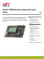
The EFM32-G8XX-STK Starter Kit is an excellent starting point to
become familiar with the EFM32G™ Gecko Microcontroller
.
The Starter Kit contains sensors and peripherals demonstrating some of the Gecko's
many capabilities. The kit provides all necessary tools for developing an EFM32G Gecko
application.
TARGET DEVICE
• EFM32G Gecko Microcontroller
(EFM32G890F128G-E-BGA112R)
•
CPU: 32-bit
ARM
®
Cortex-M3
• Memory: 128 kB flash and 16 kB RAM
KIT FEATURES
• USB connectivity
• Advanced Energy Monitor (AEM)
• SEGGER J-Link on-board debugger
• Debug Multiplexer supporting external
hardware as well as on-board MCU
• User LEDs / Pushbuttons
• 160 segment LCD
• 4-segment capacitive touch slider and
touch button
• 20-pin 2.54 mm header for expansion
boards
• Breakout pads for direct access to I/O pins
• Power sources include USB and CR2032
coin cell battery.
SOFTWARE SUPPORT
• Simplicity Studio™
• IAR Embedded Workbench
silabs.com | Building a more connected world. Rev. 2.00

Table of Contents
1. Introduction ................................
3
1.1 Description ...............................3
1.2 Features ................................3
1.3 Getting Started ..............................3
2. Kit Block Diagram .............................4
3. Kit Hardware Layout ............................5
4. Connectors ................................6
4.1 Breakout Pads ..............................6
4.2 Expansion Header .............................8
4.3 Debug Connector (DBG) ..........................10
4.4 Simplicity Connector ............................11
5. Power Supply and Reset ..........................12
5.1 MCU Power Selection ...........................12
5.2 Board Controller Power ...........................12
5.3 EFM32G Reset ..............................13
6. Peripherals ...............................14
6.1 Push Buttons and LEDs ...........................14
6.2 LCD .................................15
6.3 Capacitive Touch Slider ...........................15
6.4 Virtual COM Port .............................16
7. Advanced Energy Monitor .........................17
7.1 Usage .................................17
7.2 Theory of Operation ............................17
7.3 Accuracy and Performance ..........................17
8. On-Board Debugger ............................18
8.1 Debug Modes ..............................19
8.2 Debugging During Battery Operation ......................20
9. Kit Configuration and Upgrades .......................21
9.1 Firmware Upgrades ............................21
10. Schematics, Assembly Drawings, and BOM ..................22
11. Kit Revision History and Errata .......................23
11.1 Revision History .............................23
11.2 Errata ................................23
12. Document Revision History ........................24
silabs.com | Building a more connected world. Rev. 2.00 | 2

1. Introduction
1.1 Description
The EFM32-G8XX-STK is an excellent starting point to become familiar with the EFM32G Gecko Microcontrollers. The kit contains sen-
sors and peripherals demonstrating some of the EFM32G Gecko's many capabilities. The kit can also serve as a starting point for appli-
cation development.
In addition to supporting application development on the starter kit itself, the board is also a fully featured debugger and energy monitor-
ing tool that can be used with external applications.
1.2 Features
• EFM32G Gecko Microcontroller
• 128 kB Flash
• 16 kB RAM
• BGA112 package
• Advanced Energy Monitoring system for precise current and voltage tracking
• Integrated Segger J-Link USB debugger/emulator with the possiblity to debug external Silicon Labs devices
• 20 pin expansion header
• Breakout pads for easy access to I/O pins
• Power sources include USB and CR2032 battery
• 160 segment LCD
• 2 push buttons and 4 LEDs connected to EFM32 for user interaction
• 4-segment capacitive touch slider and touch button
• Crystals for LFXO and HFXO: 32.768 kHz and 32.000 MHz
1.3 Getting Started
Detailed instructions for how to get started with your new EFM32-G8XX-STK can be found on the Silicon Labs Web pages:
silabs.com/mcu/32-bit/efm32-gecko
UG416: EFM32G Gecko Starter Kit User's Guide
Introduction
silabs.com | Building a more connected world. Rev. 2.00 | 3

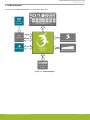
2. Kit Block Diagram
An overview of the EFM32 Gecko Starter Kit is shown in the figure below.
ACMP
LCD
4x40 Segment LCD
EXP Header
Board
Controller
USB Mini-B
Connector
DEBUG
Capacitive Touch Slider
EFM32G
MCU
GPIO
UART
GPIO
User Buttons
& LEDs
ACMP
Gecko Touch Button
Figure 2.1. Kit Block Diagram
UG416: EFM32G Gecko Starter Kit User's Guide
Kit Block Diagram
silabs.com | Building a more connected world. Rev. 2.00 | 4

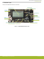
3. Kit Hardware Layout
The layout of the EFM32 Gecko Starter Kit is shown below.
Debug USB
Connector
CR2032
Battery Holder
4x40 Segment LCD
EFM32G890 MCU
EXP Header
EFM32 Reset Button
User LEDs
User Push Buttons
Power Source Select
Gecko Touch Button
Capacitive Touch Slider
Simplicity Connector
Debug Connector
Figure 3.1. EFM32-G8XX-STK Hardware Layout
UG416: EFM32G Gecko Starter Kit User's Guide
Kit Hardware Layout
silabs.com | Building a more connected world. Rev. 2.00 | 5

4. Connectors
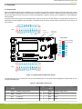
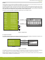
4.1 Breakout Pads
Most of the EFM32G's GPIO pins are available on two pin header rows at the top and bottom edges of the board. These have a stand-
ard 2.54 mm pitch, and pin headers can be soldered in if required. In addition to the I/O pins, connections to power rails and ground are
also provided. Note that some of the pins are used for kit peripherals or features, and may not be available for a custom application
without tradeoffs.
The figure below shows the pinout of the breakout pads, as well as the pinout of the EXP header on the right edge of the board. The
EXP header is further explained in the next section. The breakout pad connections are also printed in silk screen next to each pin for
easy reference.
GND
VMCU
PD15
PD14
PD13
PD8
GND
PD7
PD6
PD5
PD4
PD3
PD2
PD1
PD0
3V3
GND
VMCU
RST
NC
NC
NC
GND
NC
PF1
PF0
NC
PE3
PE2
PE1
PE0
3V3
J101
J102
GND
5V
PC3
PC2
PC1
PC0
GND
PB15
PB12
PB11
PB10
PB9
PA14
PA13
PA12
GND
5V
PC15
PC14
NC
PC12
GND
NC
NC
NC
NC
PC7
PC6
PC5
PC4
3V33V3
PC4
PC5
PC12
PE2
GND
PB11
PB12
PD7
5V
PD0
PD1
PD2
PD3
PD4
PD5
PD6
VMCU
3V3
Board ID SDA
Board ID SCL
EXP Header
Debug
Connector
Simplicity
Connector
R903
R919
R920
C901
R912
1 4
2
3
1
4
1
C708
C706
R793
R107
R106
31
32
R105
31
32
R104
R102
2
4
C414
1
3
L
2
C405
C417
R811
R800
C100
R900
2
4
C413
C410
11
1
1
2
3 4
C900
D803
R792
Q703
LED103
LED102
LED101
LED100
R103
C101
C415
C406
C401
B
C412
R100
R101
LED900
L400
R400
C409
C403 C402
C400 R20 4
C408
2 20
R786
1
19
ST1
D801
D800
C411
SW40 0
11
D802
R902
L600
6
4
R794
LED9 03
LED904
1
2
1
2
T100
24
C501
C500
C404C416
3
22
R904
25
SW100
R401
P701
X401
D705
11
TPH999
J101
J102
SW101
U300
C407
P601
LED9 01
SW104
P D300
48
LCD500
X400
P800
T101
P100
Figure 4.1. Breakout Pads and Expansion Header
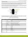
The table below shows the connections of each pin of the breakout pads. It also shows which kit peripherals or features that are con-
nected to the different pins.
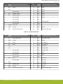
Table 4.1. Bottom Row (J101) Pinout
Pin EFM32G
I/O pin
Kit peripheral/feature connection Pin EFM32G
I/O pin
Kit peripheral/feature connection
1 VMCU EFM32G voltage domain 2 VMCU EFM32G voltage domain
3 GND Ground 4 GND Ground
5 PE0 VCOM_TX 6 PD0 EXP4
7 PE1 VCOM_RX 8 PD1 EXP6
UG416: EFM32G Gecko Starter Kit User's Guide
Connectors
silabs.com | Building a more connected world. Rev. 2.00 | 6

Pin EFM32G
I/O pin
Kit peripheral/feature connection Pin EFM32G
I/O pin
Kit peripheral/feature connection
9 PE2 EXP9 10 PD2 EXP8
11 PE3 12 PD3 EXP10
13 - Not connected 14 PD4 EXP12
15 PF0 DEBUG_SWCLK 16 PD5 EXP14
17 PF1 DEBUG_SWDIO 18 PD6 EXP16
19 Not connected 20 PD7 EXP15
21 - Not connected 22 PD8
23 - Not connected 24 PD13 VCOM_ENABLE
25 - Not connected 26 PD14
27 RESETn MCU Reset 28 PD15
29 GND Ground 30 GND Ground
31 3V3 Board controller supply 32 3V3 Board controller supply
Table 4.2. Top Row (J102) Pinout
Pin EFM32G
I/O pin
Kit peripheral/feature connection Pin EFM32G
I/O pin
Kit peripheral/feature connection
1 5V Board USB voltage 2 5V Board USB voltage
3 GND Ground 4 GND Ground
5 PC4 EXP3 6 PA12 LCD_BCAP_P
7 PC5 EXP5 8 PA13 LCD_BCAP_N
9 PC6 10 PA14 LCD_BEXT
11 PC7 12 PB9 UIF_BUTTON0
13 - Not connected 14 PB10 UIF_BUTTON1
15 - Not connected 16 PB11 EXP11
17 - Not connected 18 PB12 EXP13
19 - Not connected 20 PB15
21 PC12 EXP7 22 PC0 UIF_LED0
23 - Not connected 24 PC1 UIF_LED1
25 PC14 26 PC2 UIF_LED2
27 PC15 DEBUG_SWO 28 PC3 UIF_LED3
29 GND Ground 30 GND Ground
31 3V3 Board controller supply 32 3V3 Board controller supply
UG416: EFM32G Gecko Starter Kit User's Guide
Connectors
silabs.com | Building a more connected world. Rev. 2.00 | 7

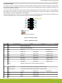
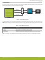
4.2 Expansion Header
On the
right hand side of the board an angled 20 pin expansion header is provided to allow connection of peripherals or plugin boards.
The connector contains a number of I/O pins that can be used with most of the EFM32G Gecko's features. Additionally, the VMCU, 3V3
and 5V power rails are also exported.
The connector follows a standard which ensures that commonly used peripherals such as a SPI, a UART, and I
2
C bus are available on
fixed locations in the connector. The rest of the pins are used for general purpose I/O. This allows the definition of expansion boards
that can plug into a number of different Silicon Labs starter kits.
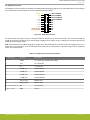
The figure below shows the pin assignment of the expansion header for the EFM32 Gecko Starter Kit. Because of limitations in the
number of available GPIO pins, some of the expansion header pins are shared with kit features.
12
4
8
6
10
3
5
9
7
12
13
14
11
1516
17
18
20 19
VMCU
PD0
PD1
PD2
PD3
PD4
PD5
PD6
5V
3V3
GND
PC4
PC5
PC12
PE2
PB1
1
PB12
PD7
BOARD_ID_SDA
BOARD_ID_SCL
Reserved (Board Identification)
TARGET I/O
Pin
Figure 4.2. Expansion Header
Table 4.3. EXP Header Pinout
Pin Connection EXP Header function Analog peripheral Peripheral mapping
20 3V3 Board controller supply
18 5V Board controller USB voltage
16 PD6 I2C_SDA I2C0_SDA #1
14 PD5 UART_RX ADC0_CH5 LEUART0_RX #0
12 PD4 UART_TX ADC0_CH4 LEUART0_TX #0
10 PD3 SPI_CS ADC0_CH3 USART1_CS #1
8 PD2 SPI_SCLK ADC0_CH2 USART1_CLK #1
6 PD1 SPI_MISO ADC0_CH1 USART1_RX #1
4 PD0 SPI_MOSI ADC0_CH0 USART1_TX #1
2 VMCU EFM32G voltage domain, included in AEM measurements.
19 BOARD_ID_SDA Connected to board controller for identification of add-on boards.
17 BOARD_ID_SCL Connected to board controller for identification of add-on boards.
15 PD7 I2C_SCL ADC0_CH7 I2C0_SCL #1
13 PB12 GPIO DAC0_OUT1
11 PB11 GPIO DAC0_OUT0
9 PE2 GPIO ACMP0_O #1
UG416: EFM32G Gecko Starter Kit User's Guide
Connectors
silabs.com | Building a more connected world. Rev. 2.00 | 8

Pin Connection EXP Header function Analog peripheral Peripheral mapping
7 PC12 GPIO ACMP1_CH4
5 PC5 GPIO ACMP0_CH5
3 PC4 GPIO ACMP0_CH4
1 GND Ground
UG416: EFM32G Gecko Starter Kit User's Guide
Connectors
silabs.com | Building a more connected world. Rev. 2.00 | 9

4.3 Debug Connector (DBG)
The debug
connector serves a dual purpose, based on the debug mode which can be set up using Simplicity Studio. If the "Debug IN"
mode is selected, the connector allows an external debugger to be used with the on-board EFM32G. If the "Debug OUT" mode is selec-
ted, the connector allows the kit to be used as a debugger towards an external target. If the "Debug MCU" mode (default) is selected,
the connector is isolated from the debug interface of both the board controller and the on-board target device.
Because this connector is automatically switched to support the different operating modes, it is only available when the board controller
is powered (J-Link USB cable connected). If debug access to the target device is required when the board controller is unpowered, this
should be done by connecting directly to the appropriate pins on the breakout header.
The pinout of the connector follows that of the standard ARM Cortex Debug 19-pin connector. The pinout is described in detail below.
Note that even though the connector supports JTAG in addition to Serial Wire Debug, it does not necessarily mean that the kit or the
on-board target device supports this.
1 2
4
8
6
10
5
9
12
13 14
11
15 16
17 18
20
19
TMS / SWDIO / C2D
TCK / SWCLK / C2CK
TDO / SWO
TDI / C2Dps
TRACECLK
TRACED0
TRACED1
TRACED2
TRACED3
RESET / C2CKps
GND
NC
NC
GND
GND
GND
7
GND
VTARGET
Cable Detect
NC
3
Figure 4.3. Debug Connector
Even though the pinout matches the pinout of an ARM Cortex Debug connector, these are not fully compatible as pin 7 is physically
removed from
the Cortex Debug connector. Some cables have a small plug that prevent them from being used when this pin is present.
If this is the case, remove the plug, or use a standard 2x10 1.27 mm straight cable instead.
Table 4.4. Debug Connector Pin Descriptions
Pin number(s) Function Note
1 VTARGET Target reference voltage. Used for shifting logical signal levels between target and
debugger.
2 TMS / SDWIO / C2D JTAG test mode select, Serial Wire data or C2 data
4 TCK / SWCLK / C2CK JTAG test clock, Serial Wire clock or C2 clock
6 TDO/SWO JTAG test data out or Serial Wire Output
8 TDI / C2Dps JTAG test data in, or C2D "pin sharing" function
10 RESET / C2CKps Target device reset, or C2CK "pin sharing" function
12 NC TRACECLK
14 NC TRACED0
16 NC TRACED1
18 NC TRACED2
20 NC TRACED3
9 Cable detect Connect to ground
11, 13 NC Not connected
3, 5, 15, 17, 19 GND
UG416: EFM32G Gecko Starter Kit User's Guide
Connectors
silabs.com | Building a more connected world. Rev. 2.00 | 10

4.4 Simplicity Connector
The Simplicity
Connector featured on the Starter Kit enables advanced debugging features such as the AEM and the Virtual COM port
to be used towards an external target. The pinout is illustrated in the figure below.
VMCU
1
33V3
5
5V
15
GND
13
GND
11
GND
9
GND
7
GND
17
Board ID SCL
19
Board ID SDA
2
Virtual COM TX
4 Virtual COM RX
6 Virtual COM CTS
8
Virtual COM RTS
10
NC
12
NC
14
NC
16
NC
18
NC
20
NC
Figure 4.4. Simplicity Connector
The signal names in the figure and the pin description table are referenced from the board controller. This means that VCOM_TX
should be
connected to the RX pin on the external target, VCOM_RX to the target's TX pin, VCOM_CTS to the target's RTS pin and
VCOM_RTS to the target's CTS pin.
Note: Current drawn from the VMCU voltage pin is included in the AEM measurements, while the 3V3 and 5V voltage pins are not. To
monitor the current consumption of an external target with the AEM, put the on-board MCU in its lowest energy mode to minimize its
impact on the measurements.
Table 4.5. Simplicity Connector Pin Descriptions
Pin number(s) Function Description
1 VMCU 3.3 V power rail, monitored by the AEM
3 3V3 3.3 V power rail
5 5V 5 V power rail
2 VCOM_TX Virtual COM TX
4 VCOM_RX Virtual COM RX
6 VCOM_CTS Virtual COM CTS
8 VCOM_RTS Virtual COM RTS
17 EXT_ID_SCL Board ID SCL
19 EXT_ID_SDA Board ID SDA
10, 12, 14, 16, 18, 20 NC Not connected
7, 9, 11, 13, 15 GND Ground
UG416: EFM32G Gecko Starter Kit User's Guide
Connectors
silabs.com | Building a more connected world. Rev. 2.00 | 11

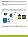
5. Power Supply and Reset
5.1 MCU Power Selection
The EFM32G on the Starter Kit can be powered by one of these sources:
• The debug USB cable
• 3 V coin cell battery
The power source for the MCU is selected with the slide switch in the lower left corner of the Starter Kit. The figure below shows how
the different power sources can be selected with the slide switch.
3.3 V
VMCU
AEM
BAT
USB Mini-B
Connector
Advanced
Monitor
5 V
3 V Lithium Battery
(CR2032)
EFM32G
BAT
AE
M
LDO
Advanced
Energy
Monitor
SENSE
Figure 5.1. Power Switch
With the switch in the AEM
position,
a low noise 3.3 V LDO on the Starter Kit is used to power the EFM32G. This LDO is again pow-
ered from the debug USB cable. The Advanced Energy Monitor is now connected in series, allowing accurate high-speed current
measurements and energy debugging/profiling.
With the switch in the BAT position, a 20 mm coin cell battery in the CR2032 socket can be used to power the device. With the switch
in this position, no current measurements are active. This is the recommended switch position when powering the MCU with an external
power source.
Note: The Advanced Energy Monitor can only measure the current consumption of the EFM32G when the power selection switch is in
the AEM position.
5.2 Board Controller Power
The board controller is responsible for important features, such as the debugger and the AEM, and is powered exclusively through the
USB port in the top left corner of the board. This part of the kit resides on a separate power domain, so a different power source can be
selected for the target device while retaining debugging functionality. This power domain is also isolated to prevent current leakage
from the target power domain when power to the board controller is removed.
The board controller power domain is not influenced by the position of the power switch.
The kit has been carefully designed to keep the board controller and the target power domains isolated from each other as one of them
powers down. This ensures that the target EFM32G device will continue to operate in the BAT mode.
UG416: EFM32G Gecko Starter Kit User's Guide
Power Supply and Reset
silabs.com | Building a more connected world. Rev. 2.00 | 12

5.3 EFM32G Reset
The EFM32G MCU can be reset by a few different sources:
• A user pressing the RESET button
•
The on-board debugger pulling the #RESET pin low
• An external debugger pulling the #RESET pin low
In addition to the reset sources mentioned above, a reset to the EFM32G will also be issued during board controller boot-up. This
means that removing power to the board controller (unplugging the J-Link USB cable) will not generate a reset, but plugging the cable
back in will, as the board controller boots up.
UG416: EFM32G Gecko Starter Kit User's Guide
Power Supply and Reset
silabs.com | Building a more connected world. Rev. 2.00 | 13

6. Peripherals
The starter kit has a set of peripherals that showcase some of the features of the EFM32G.
Note that most EFM32G I/O routed to peripherals are also routed to the breakout pads or the EXP header, which must be taken into
consideration when using these.
6.1 Push Buttons and LEDs
The kit has two user push buttons marked BTN0 and BTN1. They are connected directly to the EFM32G and are debounced by RC
filters with a time constant of 1 ms. The buttons are connected to pins PB9 and PB10.
The kit also features four yellow LEDs marked LED0 through LED3 that are controlled by GPIO pins on the EFM32G. The LEDs are
connected to pins PC0, PC1, PC2 and PC3 in an active-high configuration.
PC1 (GPIO)
User Buttons
& LEDs
UIF_LED0
PB9 (GPIO)
PB10
(GPIO)
PC0 (GPIO)
EFM32G
UIF_BUTTON1
UIF_LED1
PC2 (GPIO)
PC3 (GPIO)
UIF_LED2
UIF_LED3
UIF_BUTTON0
Figure 6.1. Buttons and LEDs
UG416: EFM32G Gecko Starter Kit User's Guide
Peripherals
silabs.com | Building a more connected world. Rev. 2.00 | 14

6.2 LCD
A 48-pin
segment LCD is connected to the EFM32's LCD peripheral. The LCD has 4 common lines and 40 segment lines, giving a total
of 160 segments in quadruplex mode. These lines are not shared on the breakout pads.
It is possible to operate less than 4 common lines to prevent the LCD from occupying more I/O resources than required. This is accom-
plished by disabling any number of the COM1-3 lines, for static, duplex and triplex modes respectively. Only COM0 is operated in static
mode, while COM0-1 is operated in duplex mode, and COM0-2 is operated in triplex mode. Refer to the kit schematics for details about
which segments that will be available when operating the display in different multiplexing modes.
A capacitor connected to the EFM32 LCD peripheral's voltage boost pin is also available on the kit.
EFM32G
LCD_SEG[39:35]
LCD_SEG[31:28]
LCD_BCAP[N,
P]
LCD_SEG[34:32]
PA[11:7]
PB[2:0]
PD[12:9]
PA[13:12]
PB[6:3]
PA[6:0]
PF[9:6]
PE[7:4]
LCD_SEG[23:20]
LCD_SEG[27:24]
LCD_COM[3:0]
LCD_SEG
LCD_COM
PA14
LCD_BEXT
1 uF
4x40 Segment LCD
22 nF
LCD_SEG[19:13]
PA15
LCD_SEG12
PE[15:8]
L
CD_SEG[11:4]
PF[5:2]
LCD_SEG[3:0]
Figure 6.2. Segment LCD
6.3 Capacitive Touch Slider
A touch slider utilizing the capacitive touch capability of the EFM32G's analog comparator (ACMP) is located below the segment LCD. It
consists of four interleaved pads which are connected to
PC8, PC9, PC10 and PC11.
PC8 (ACMP1 CH0)
PC9 (ACMP1
CH1)
UIF_TOUCH0
UIF_TOUCH1
EFM32G
Capacitive Touch Slider
UIF_TOUCH2
UIF_TOUCH3
PC10 (ACMP1 CH2)
PC1
1 (ACMP1
CH3)
Figure 6.3. Touch Slider
The capacitive touch pads work by sensing changes in the capacitance of the pads when touched by a human finger. Sensing the
changes in capacitance is done by setting up the EFM32G's analog comparator (ACMP) in capacitive touch sensing mode.
Sensing change in capacitance is done by setting up the touch pad as part of an RC relaxation oscillator, where the analog comparator
counts the number of oscillations for a fixed period of time.
UG416: EFM32G Gecko Starter Kit User's Guide
Peripherals
silabs.com | Building a more connected world. Rev. 2.00 | 15

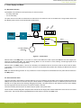
6.4 Virtual COM Port
An asynchronous
serial connection to the board controller is provided for application data transfer between a host PC and the target
EFM32G, which eliminates the need for an external serial port adapter.
VCOM_EN
PE0 (U0_TX #1)
PE1 (U0_RX #1)
PD13
(GPIO)
VCOM_RX
VCOM_TX
Board
Controller
EFM32
USB
Host
Computer
Isolation
Switch
Figure 6.4. Virtual COM Port Interface
The Virtual COM port consists of a physical UART between the target device and the board controller, and a logical function in the
board controller
that makes the serial port available to the host PC over USB. The UART interface consists of two pins and an enable
signal.
Table 6.1. Virtual COM Port Interface Pins
Signal Description
VCOM_TX Transmit data from the EFM32G to the board controller
VCOM_RX Receive data from the board controller to the EFM32G
VCOM_ENABLE Enables the VCOM interface, allowing data to pass through to the board controller.
Note: The VCOM port is only available when the board controller is powered, which requires the J-Link USB cable to be inserted.
UG416: EFM32G Gecko Starter Kit User's Guide
Peripherals
silabs.com | Building a more connected world. Rev. 2.00 | 16

7. Advanced Energy Monitor
7.1 Usage
The Advanced Energy Monitor (AEM) data is collected by the board controller and can be displayed by the Energy Profiler, available
through Simplicity Studio. By using the Energy Profiler, current consumption and voltage can be measured and linked to the actual
code running on the EFM32G in realtime.
7.2 Theory of Operation
To accurately measure current ranging from 0.1 µA to 47 mA (114 dB dynamic range), a current sense amplifier is utilized together with
a dual gain stage. The current sense amplifier measures the voltage drop over a small series resistor, and the gain stage further ampli-
fies this voltage with two different gain settings to obtain two current ranges. The transition between these two ranges occurs around
250 µA. Digital filtering and averaging is done within the board controller before the samples are exported to the Energy Profiler applica-
tion.
During kit startup, an automatic calibration of the AEM is performed, which compensates for the offset error in the sense amplifiers.
4.7Ω
Sense Resistor
LDO
3.3V VMCU
Current Sense
Amplifier
AEM
Processing
Multiple Gain
Stages
EFM32G
Peripherals
Power Select
Switch
5V
G
0
G
1
Figure 7.1. Advanced Energy Monitor
7.3 Accuracy and Performance
The AEM
is capable of measuring currents in the range of 0.1 µA to 47 mA. For currents above 250 µA, the AEM is accurate within 0.1
mA. When measuring currents below 250 µA, the accuracy increases to 1 µA. Although the absolute accuracy is 1 µA in the sub 250
µA range, the AEM is able to detect changes in the current consumption as small as 100 nA. The AEM produces 6250 current samples
per second.
UG416: EFM32G Gecko Starter Kit User's Guide
Advanced Energy Monitor
silabs.com | Building a more connected world. Rev. 2.00 | 17

8. On-Board Debugger
The EFM32-G8XX-STK contains an integrated debugger, which can be used to download code and debug the EFM32G. In addition to
programming the EFM32G on the kit, the debugger can also be used to program and debug external Silicon Labs EFM32, EFM8,
EZR32 and EFR32 devices.
The debugger supports three different debug interfaces used with Silicon Labs devices:
• Serial Wire Debug, which is used with all EFM32, EFR32 and EZR32 devices
• JTAG, which can be used with EFR32 and some EFM32 devices
• C2 Debug, which is used with EFM8 devices
To ensure accurate debugging, use the appropriate debug interface for your device. The debug connector on the board supports all
three of these modes.
UG416: EFM32G Gecko Starter Kit User's Guide
On-Board Debugger
silabs.com | Building a more connected world. Rev. 2.00 | 18

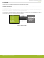
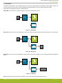
8.1 Debug Modes
To program
external devices, use the debug connector to connect to a target board and set the debug mode to [Out]. The same con-
nector can also be used to connect an external debugger to the EFM32G MCU on the kit by setting debug mode to [In].
Selecting the active debug mode is done in Simplicity Studio.
Debug MCU: In this mode, the on-board debugger is connected to the EFM32G on the kit.
EFM32G
Board
Controller
USB
Host
Computer
DEBUG HEADER
External
Hardware
Figure 8.1. Debug MCU
Debug OUT: In this mode, the on-board debugger can be used to debug a supported Silicon Labs device mounted on a custom board.
Board
Controller
USB
Host
Computer
DEBUG HEADER
External
Hardware
EFM32G
Figure 8.2. Debug OUT
Debug IN: In this mode, the on-board debugger is disconnected, and an external debugger can be connected to debug the EFM32G
on
the kit.
Board
Controller
USB
Host
Computer
DEBUG HEADER
External Debug Probe
EFM32G
Figure 8.3. Debug IN
Note: For "Debug IN" to work, the kit board controller must be powered through the Debug USB connector.
UG416: EFM32G Gecko Starter Kit User's Guide
On-Board Debugger
silabs.com | Building a more connected world. Rev. 2.00 | 19

8.2 Debugging During Battery Operation
When the
EFM32G is battery-powered and the J-Link USB is still connected, the on-board debug functionality is available. If the USB
power is disconnected, the Debug IN mode will stop working.
If debug access is required when the target is running off another energy source, such as a battery, and the board controller is powered
down, make direct connections to the GPIO used for debugging. This can be done by connecting to the appropriate pins of the breakout
pads. Some Silicon Labs kits provide a dedicated pin header for this purpose.
UG416: EFM32G Gecko Starter Kit User's Guide
On-Board Debugger
silabs.com | Building a more connected world. Rev. 2.00 | 20
Page is loading ...
Page is loading ...
Page is loading ...
Page is loading ...
Page is loading ...
-
 1
1
-
 2
2
-
 3
3
-
 4
4
-
 5
5
-
 6
6
-
 7
7
-
 8
8
-
 9
9
-
 10
10
-
 11
11
-
 12
12
-
 13
13
-
 14
14
-
 15
15
-
 16
16
-
 17
17
-
 18
18
-
 19
19
-
 20
20
-
 21
21
-
 22
22
-
 23
23
-
 24
24
-
 25
25


Ask a question and I''ll find the answer in the document
Finding information in a document is now easier with AI
Related papers
-
Silicon Labs UG417 User guide
-
-
-
-
-
-
Silicon Labs UG274 User guide
-
-
-
Other documents
-
takeMS TMS2GUMIR1R05 Datasheet
-
Gecko GG100021 Datasheet
-
Fujitsu MB9B500 Series User manual
-
-
-
Gardner Bender 10-PC3 Specification
-
-
ST SPC574S-DISP Sphaero Discovery+ User manual
-
 Segger 6.30.00 EMPOWER EVALUATION BOARD Operating instructions
-
