Page is loading ...

www.furuno.com
A
ll brand and product names are trademarks, registered trademarks or service marks of their respective holders.
Installation Manual
AUTOPILOT
Model NAVpilot-300
SAFETY INSTRUCTIONS ................................................................................................ i
SYSTEM CONFIGURATION ........................................................................................... ii
EQUIPMENT LISTS........................................................................................................ iii
1. MOUNTING..............................................................................................................1-1
1.1 Control Unit ........................................................................................................................1-1
1.2 Processor Unit ...................................................................................................................1-5
1.3 Rudder Reference Unit (Option) ........................................................................................1-8
2. WIRING....................................................................................................................2-1
2.1 Processor Unit ...................................................................................................................2-3
2.2 Control Unit ........................................................................................................................2-5
2.3 Junction Box (Option) ........................................................................................................2-6
2.4 Input/Output PGNs.............................................................................................................2-8
3. INITIAL SETTING ....................................................................................................3-1
3.1 [Initialization] Menu ............................................................................................................3-1
3.2 [Display Setup] Menu.........................................................................................................3-3
3.3 [Ship’s Characteristics] Menu ............................................................................................3-3
3.4 [Dockside Setup] Menu......................................................................................................3-4
3.5 [NMEA2000] Menu...........................................................................................................3-17
3.6 [Drive by Wire Port] Menu................................................................................................3-18
3.7 [Sensors Selection] Menu ................................................................................................3-18
3.8 [Sea Trial] Menu...............................................................................................................3-19
3.9 [Parameter Setup] Menu..................................................................................................3-22
3.10 [Auto Pilot Option] Menu ..................................................................................................3-25
3.11 [Fish Hunter Option] Menu...............................................................................................3-26
3.12 [System Setup] Menu.......................................................................................................3-29
3.13 Pairing the Gesture Controller ([Wireless RC] Menu) ......................................................3-31
3.14 [Alert] Menu......................................................................................................................3-32
APPENDIX 1 JIS CABLE GUIDE .............................................................................AP-1
PACKING LISTS ......................................................................................................... A-1
OUTLINE DRAWING................................................................................................... D-1
INTERCONNECTION DIAGRAM ................................................................................ S-1

7KHSDSHUXVHGLQWKLVPDQXDO
LVHOHPHQWDOFKORULQHIUHH
࣭)85812$XWKRUL]HG'LVWULEXWRU'HDOHU
$VKLKDUDFKR
1LVKLQRPL\D-$3$1
$ 2&7
3ULQWHGLQ-DSDQ
$OOULJKWVUHVHUYHG
& -8/
3XE1R ,0(&
(70, 1$9SLORW

i
SAFETY INSTRUCTIONS
The installer must read the appropriate safety instructions before attempting to install the equip-
ment.
Note: For Gesture Controller (GC-001) safety instructions, see the User’s Guide (C72-01603).
Indicates a condition that can cause death or serious injury if
not avoided.
Indicates a condition that can cause minor or moderate injury if
not avoided.
WARNING
CAUTION
Warning, CautionProhibitive Action
Mandatory Action
WARNING
WARNING
CAUTION
CAUTION
Turn off the power at the mains
switchboard before beginning the
installation.
Fire, electrical shock or serious injury can
result if the power is left on or is applied
while the equipment is being installed.
ELECTRICAL SHOCK HAZARD
Do not open the equipment unless
totally familar with electrical circuits
and service manual.
Only qualified personnel are allowed to
workinside the equipment. For the
serviceman: Make sure the waterproofing
gasket is correctly seated in the groove in
the chassis before closing the cover.
When connecting a geomagnetism
detection type heading sensor, correct
magnetic field deviation.
If an autopilot is used without the
compensation, unexpected course
change may occur.
Confirm that no one is near the rudder
when bleeding air from oil cylinder.
The rudder may move unexpectedly,
possibly causing bodily injury.
Confirm that the power supply voltage
is compatible with the voltage rating of
the equipment.
Connection to the wrong power supply
can cause fire or damage the equipment.
Observe the following compass safe
distances to prevent interference to a
magnetic compass:
Unit
0.55 m 0.35 m
0.30 m 0.30 m
Standard
compass
Steering
compass
Control Unit
FAP-3011
Processor Unit
FAP-3012
Separate the reversible pump at least
one meter from communications
equipment, communications antenna
and communications cabling to
prevent interference.
Input the correct ship’s speed data.
The NAVpilot cannot control the rudder
properly, if the incorrect ship’s speed is
input.
WARNING
WARNING
Install an control unit (or emergency
stop button) at each helm station, to
allow you to disable the autopilot in
an emergency.
If the autopilot cannot be disabled,
accidents may result.
Do not allow unit to be wet by waves,
spray or heavy rain in inclement
weather.
Electrical fire and/or electrical shock can
result.

ii
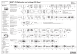
SYSTEM CONFIGURATION
12/24 VDC
Reversible Pump
Junction Box
Linear Sensor
Safe Helm System
Event Switch
Rudder Reference Unit
FAP-6112
Gesture Controller
GC-001 (Max. 3 Units)
Processor Unit
FAP-3012
Junction Box
*
1
: Termination resistors must be installed at both ends of the backbone.
*
2
: EVC systems compatible with the NAVpilot are as follows:
Termination
resistor*
1
Control Unit
FAP-3011 (Max. 3 Units)
15 VDC
: Standard supply
: Option or local supply
Junction Box
FI-5002
Termination
resistor*
1
Integrated Heading Sensor
PG-700
CAN bus (NMEA2000)
Device
EVC System
*
2
EVC System Remarks
VOLVO PENTA IPS
YAMAHA Helm Master
YANMAR VC10
SEASTAR SOLUTIONS OPTIMUS
Requires VOLVO IPS gateway (available as an optional extra).
Requires YAMAHA HM gateway (available as an optional extra).
-
The software version of the Main PCM (Pump Control Module)
must be “Rev. T” or later.

iii
EQUIPMENT LISTS
Standard supply
Option
Name Type Code No. Qty Remarks
Control Unit FAP-3011 - 1
Processor Unit FAP-3012 - 1
Gesture Controller GC-001 - 1
Installation Materials
CP64-03400 001-472-360 1 For control unit
CP64-02501 009-000-880 1 For processor unit
Accessories FP64-01501 001-482-130 1 Batteries for GC-001
Spare Parts SP64-01701 001-485-540 1 For processor unit, fuse
Name Type Code No. Remarks
Control Unit FAP-3011 -
Gesture Controller GC-001 -
Junction Box FI-5002 - For CAN bus connection
Rudder Reference Unit FAP-6112-200 -
VOLVO IPS Gateway AUTOPILOT-GATEWAY -
For VOLVO PENTA IPS
system connection
YAMAHA HM Gateway YAMAHA-HM-GATEWAY -
For YAMAHA Helm Mas-
ter system connection
Bracket Kit OP64-13 000-033-337 For control unit
Cable Assembly
FI-70-0600 001-490-200
With micro type connec-
tors (one side: L-type
connector), 6 m
M12-05BM+05BF-010 001-105-750-10
With micro type connec-
tors, 1 m
M12-05BM+05BF-020 001-105-760-10
With micro type connec-
tors, 2 m
M12-05BM+05BF-060 001-105-770-10
With micro type connec-
tors, 6 m
M12-05BFFM-010 001-105-780-10
With micro type connec-
tor, 1 m
M12-05BFFM-020 001-105-790-10
With micro type connec-
tor, 2 m
M12-05BFFM-060 001-105-800-10
With micro type connec-
tor, 6 m
CB-05PM+05BF-010 000-167-968-11
With mini type connec-
tors, 1 m
CB-05PM+05BF-020 000-167-969-11
With mini type connec-
tors, 2 m
CB-05PM+05BF-060 000-167-970-11
With mini type connec-
tors, 6 m
CB-05BFFM-010 000-167-971-11
With mini type connec-
tor, 1 m
CB-05BFFM-020 000-167-972-11
With mini type connec-
tor, 2 m

EQUIPMENT LISTS
iv
Cable Assembly CB-05BFFM-060 000-167-973-11
With mini type connec-
tor, 6 m
Micro T-Connector SS-050505-FMF-TS001 000-168-603-10
Mini/Micro T-Connector NC-050505-FMF-TS001 000-160-507-10
Termination Resistor
(Micro)
LTWMC-05BMMT-SL8001 000-168-604-10 Male
LTWMC-05BFFT-SL8001 000-168-605-10 Female
Termination Resistor
(Mini)
LTWMN-05AMMT-SL8001 000-160-508-10 Male
LTWMN-05AFFT-SL8001 000-160-509-10 Female
Name Type Code No. Remarks

1-1
1. MOUNTING
The installer of this equipment must be familiar with the hydraulic system and have the
experience of installing the ship’s steering equipment.
The NAVpilot-300 is design for use in 25 ft or larger boats with inboard, outboard, in/
outboard engines or DBW engines*.
1.1 Control Unit
The control unit can be installed with one the following three methods:
• Flush mount: Secured from the rear side of the mounting hole.
• Front mount: Secured from the front side of the mounting hole.
• Desktop mount: Requires optional bracket kit (OP64-13). For desktop mount instal-
lation instructions, see the installation instruction (C72-01605) supplied with bracket
kit.
Mounting consideration
Select a mounting location, keeping in mind the following points:
• Select a location where the unit can easily be operated.
• Do not install the unit under "Plexiglas" or other types of shielding material.
Plexiglas can trap heat and moisture or magnify sunlight on the surface of the dis-
play.
• Locate the unit away from exhaust pipes and ventilators.
• The mounting location should be well ventilated.
• Select a location where shock and vibration are minimal.
• Leave sufficient space for maintenance and service, referring to the outline draw-
ings at the back of this manual.
• Select a mounting location considering the length of the cables to be connected to
the unit.
*: DBW (Drive By Wire) systems compatible with the NAVpilot-300 are as follows:
• VOLVO PENTA IPS • YAMAHA Helm Master
• YANMAR VC10 • SEASTAR SOLUTIONS OPTIMUS
(The software version of the Main PCM (Pump
Control Module) must be “Rev. T” or later.)
NOTICE
Do not apply paint, anti-corrosive sealant
or contact spray to coating or plastic
parts of the equipment.
Those items contain organic solvents that
can damage coating and plastic parts,
especially plastic connectors.

1. MOUNTING
1-2
• A magnetic compass will be affected if the unit is placed too close to the magnetic
compass. Observe the compass safe distances at the front of this manual to prevent
interference to a magnetic compass.
1.1.1 Flush mount
Supplied installation materials
Required tools
The following tools should be prepared in advance for this installation.
1. Make a mounting hole in the mounting location and two bolt holes for the threaded
rods, using the supplied mounting template.
Note: Be sure to use “Flush Mounting Template”.
2. Fit the supplied threaded rods (M3u40) to the rear of the unit.
Note: Do not use tools to fit or insert the threaded rods.
3. Fit the supplied flush mount sponge to the rear of th the unit.
4. Feed the cable through the mounting hole, then connect the cable to the unit.
5. Set the unit into the mounting hole.
Name Remarks
Electrical Drill For making the bolt holes for threaded rods.
Drill Bit I3.5
Tank Cutter For making the mounting hole (I90 mm).
File For smoothing the cut edge of the mounting hole.
Note: These installation materials are used for
front mounting.
Unused installation materials (CP64-03401)
Installation materials for flush mounting (CP26-02001)
• Flush mount sponge × 1
• Spring washer × 2
• Flat washer × 2
• Stud bolt × 2
• Wing nut × 2
• Mount base assembly × 1 • Self-tapping screw × 4
• Flat washer × 2
• Snap pin × 2
• Cable assembly (FI-70-0600) × 1
NAVpilot-300
Flush Mounting Template
䝣䝷䝑䝅䝳䝬䜴䞁䝖⏝㻌ᆺ⣬
30±0.5 mm (1.18")
㻠㻡
㼼
㻜㻚㻡㻌
mm
(
1
.
7
7")
30
±
0
.
5
mm
(
1.
1
8")
㻠㻡㼼㻜㻚㻡㻌mm (1.77")
ø
9
0
+2
-0
m
m
(
3.
5
4
"
)
Cut out shaded area only
ᩳ⥺㒊ษྲྀ䜚
January 2017 Printed in Japan
Pub. No.
C72-01602-A
Note: This template may have expanded or shrunk slightly.
Please confirm dimensions before use.
ὀព㻦㻌ᮏᆺ⣬䛿ಖᏑ≧ែ䛻䜘䜚ⱝᖸఙ⦰䛩䜛ሙྜ䛜䛒䜚䜎䛩䚹
㻌㻌㻌㻌㻌㻌㻌㻌⏝䛾㝿䛻䛿ᑍἲ䜢☜ㄆ䛧䛶䛟䛰䛥䛔䚹
Front Mounting Template
䝣䝻䞁䝖䝬䜴䞁䝖⏝㻌ᆺ⣬
3
0
±0.
5
m
m
(
1
.1
8
"
)
30±0.5 mm (1.18")
㻠㻡㼼㻜㻚㻡㻌mm (1.77")
㻠㻡㼼
㻜㻚
㻡
㻌
mm
(
1
.
7
7"
)
Cut out shaded area only
ᩳ⥺㒊ษྲྀ䜚
㻥
㻜
㼼㻜㻚㻡㻌
m
m
(3.
5
4
")
㻥㻜㼼㻜㻚㻡㻌mm (3.54")
ø9
0
+
2
-
0
m
m
(
3
.
5
4
"
)
䢲䢲䢲䢳䢻䢵䢴䢻䢻䢳䢲
ø3.5
• Mounting template × 1

1. MOUNTING
1-3
6. Fit the supplied flat washers, spring washers and wing nuts to the threaded rod,
then fasten the wing nuts to secure the unit.
When using locally supplied materials
When using locally supplied screws to secure the control
unit, thread depth should be approx. 5 mm, as indicated
in the figure to the right.
1.1.2 Front mount
Supplied installation materials
Threaded rod
Console
Flush mount sponge
Flat washer
Spring washer
Wing nut
Console
Control unit
Approx. 5 mm
Note: These installation materials are used
for flush mounting.
Installation materials for front mounting (CP64-03401)
• Flush mount sponge × 1
• Spring washer × 2
• Flat washer × 2
• Stud bolt × 2
• Wing nut × 2
• Mount base assembly × 1 • Self-tapping screw × 4
• Flat washer × 2
• Snap pin × 2
Unused installation materials (CP26-02001)
• Cable assembly (FI-70-0600) × 1
NAVpilot-300
Flush Mounting Template
䝣䝷䝑䝅䝳䝬䜴䞁䝖⏝㻌ᆺ⣬
30±0.5 mm (1.18")
㻠㻡
㼼
㻜㻚㻡㻌
m
m
(
1
.
7
7"
)
30
±
0.5
mm
(
1
.
18
")
㻠㻡㼼㻜㻚㻡㻌mm (1.77")
ø
9
0
+
2
-0
m
m
(
3.
5
4
"
)
Cut out shaded area only
ᩳ⥺㒊ษྲྀ䜚
January 2017 Printed in Japan
Pub. No.
C72-01602-A
Note: This template may have expanded or shrunk slightly.
Please confirm dimensions before use.
ὀព㻦㻌ᮏᆺ⣬䛿ಖᏑ≧ែ䛻䜘䜚ⱝᖸఙ⦰䛩䜛ሙྜ䛜䛒䜚䜎䛩䚹
㻌㻌㻌㻌㻌㻌㻌㻌⏝䛾㝿䛻䛿ᑍἲ䜢☜ㄆ䛧䛶䛟䛰䛥䛔䚹
Front Mounting Template
䝣䝻䞁䝖䝬䜴䞁䝖⏝㻌ᆺ⣬
3
0
±
0.
5
mm
(
1
.1
8
"
)
30±0.5 mm (1.18")
㻠㻡㼼㻜㻚㻡㻌mm (1.77")
㻠㻡㼼㻜㻚
㻡
㻌m
m
(
1
.7
7
"
)
Cut out shaded area only
ᩳ⥺㒊ษྲྀ䜚
㻥
㻜
㼼㻜㻚㻡㻌
m
m
(
3
.
54"
)
㻥㻜㼼㻜㻚㻡㻌mm (3.54")
ø90
+
2
-
0
m
m
(
3
.
54
"
)
䢲䢲䢲䢳䢻䢵䢴䢻䢻䢳䢲
ø3.5
• Mounting template × 1

1. MOUNTING
1-4
Required tools
The following tools should be prepared in advance for this installation.
1. Make a mounting hole in the mounting location and four pilot holes for the self-
tapping screws, using the supplied mounting template.
Note: Be sure to use “Front Mounting Template”.
2. Insert the supplied flat washers and snap pins to the rear of the unit.
3. Secure the supplied mount base assembly to the mounting
hole, using the supplied self-tapping screws (I3u20).
Note: Check that the mount base assembly is oriented in the
correct manner, referring to the figure to the right.
4. Feed the cable through the mounting hole, then connect the
cable to the unit.
5. Set the control unit into the mount base assembly, using the
snap pins and snap pin slots as guides.
Push the unit into the mount base assembly until a “click”
sound is made, indicating that the unit is now secured.
How to remove a front mounted control unit
To remove the control unit from the
mount base assembly, release the
pin holders at the back of the panel,
then remove the unit. Forced remov-
al may damage the pin holders, snap
pins, mount base assembly or the
control unit.
Name Remarks
Electrical Drill For making the pilot boles for self-tapping screws.
Drill Bit I2.5
Tank Cutter For making the mounting hole (I90 mm).
Hole Saw (I19 mm) For making holes for the snap pin slot.
File For smoothing the cut edge of the mounting hole.
Phillips-head Screw Driver #2
Snap pin
slots
Snap pin
Self-tapping
screw (Ø3×20)
Mount base
assembly
Console
Flat washer
Console rearConsole rear
Pin holders
Snap pinSnap pin
Release the pin holderRelease the pin holder

1. MOUNTING
1-5
1.2 Processor Unit
The processor unit can be installed on a desktop or on a bulkhead.
Mounting consideration
Select a mounting location, keeping in mind the following points:
• Perform a communication test between the processor unit and gesture controller,
before mounting the processor unit. For how to perform the communication test,
see section 1.2.1.
• Do not install the unit in a metal shield body, which may obstruct communication
with the gesture controller.
• Select a location where obstructions between the processor unit and gesture con-
troller is minimal.
Obstructions between the processor unit and gesture controller reduce the commu-
nicable range.
• Select a location where the gesture controller is visible from the mounting location
of the processor unit (ex. flying bridge).
• Locate the unit away from direct sunlight
• Locate the unit away from places subject to water splash and rain.
• Locate the unit away from exhaust pipes and ventilators.
• The mounting location should be well ventilated.
• Select a location where the shock and vibration are minimal.
• For the installation on a bulkhead, make sure the mounting location is strong
enough to support the unit under the pitching and rolling normally found on the boat.
• Leave sufficient space for maintenance and service, referring to the outline draw-
ings at the back of this manual.
• Select a mounting location considering the length of the cables to be connected to
the unit.
• A magnetic compass will be affected if the unit is placed too close to the magnetic
compass. Observe the compass safe distances at the front of this manual to prevent
interference to a magnetic compass.
• For installation on a bulkhead, secure the unit so that the cables face downward.
OK
UP

1. MOUNTING
1-6
1.2.1 Bluetooth
®
communication test before mounting
The processor unit communicates with the gesture controller via the Bluetooth
®
wire-
less technology*. Before mounting the unit, perform a communication test at the
planned mounting location, to check that Bluetooth
®
communication is established
correctly. If the Bluetooth communication is not established, change the mounting lo-
cation and perform the communication test again.
*: The Bluetooth
®
word mark and logos are registered trademarks of Bluetooth SIG,
Inc.
1. Connect the units referring to the following figure.
2. Turn on the processor unit, control unit and gesture controller.
3. Pair the gesture controller to the processor unit, referring to section 3.13.
4. Move to the location where you use the gesture controller.
5. Turn your back on the location where the processor unit is located.
Your body should be located between the processor unit and gesture controller
during the communication test.
6. Press the on the gesture controller to open the menu, then select [SYSTEM
MENU]o[DIAGNOSTIC]o[BT TEST].
7. Confirm the test result.
• When [BLE] is “-80 DBM” or higher, the communica-
tion is stable. The planned installation location for the
processor unit is good.
• When [BLE] is lower than “-80 DBM”, the communi-
cation is unstable. In this case, the communication
error is more likely to occur. Change the installation
location and retry the communication test.
12/24 VDC
Processor unit
15 VDC
Control unit
CAN bus/NMEA2000 backbone
BT MODULE S:
6454031-EF.02
BLE: -58DBM
Test result
Check this
value.

1. MOUNTING
1-7
1.2.2 Mounting
Mount the unit on a bulkhead or desktop.
Supplied installation materials
• Self-tapping screw u4
Required tools
The following tools should be prepared in advance for this installation.
1. Drill four pilot holes in the bulkhead or desktop for self-tapping screws.
2. Screw two self-tapping screws (I4u20) into the upper pilot holes, leave 5 mm pro-
truding.
3. Hang (or set) the notches of the unit onto the screws fastened at step 2.
4. Screw two self-tapping screws (I4u20) into the lower fixing holes.
5. Fasten all screws tightly to secure the unit in place.
Name Remarks
Electrical Drill For making the pilot holes for self-tapping screws.
Drill Bit I3.5
Phillips-head Screw Driver #2
Self-tapping screws
(Ø4×20, 4 pcs)
Top

1. MOUNTING
1-8
1.3 Rudder Reference Unit (Option)
Note 1: This unit is not required for Fantum Feedback
™
and EVC system equipped
boats. For details of Fantum Feedback
™
, see section 1.3.5.
Note 2: SEASTAR SOLUTIONS linear sensor AR4502 is available with the NAVpilot,
instead of the rudder reference unit. For installation instructions, see the linear sensor
operator’s manual.
Mounting consideration
Select a mounting location, keeping in mind the following points:
• Leave sufficient space around all moving parts.
• The unit must be fastened to the rudder as shown below, where the following con-
ditions are met:
350 mm (13.8") < Y2 < 540 mm (21.3")
X1 = X2
Y1 = Y2
1.3.1 Mounting
Supplied installation materials
Required tools
The following tools should be prepared in advance for this installation.
Name Remarks
Electrical Drill For making the pilot holes for self-tapping screw.
Drill Bit I3.5
Phillips-head Screw Driver #2
Wrench For M6 (hex. size 10 mm)
X1
X2
Y1
Y2
90
°
Top view
RRU
Rudder
90
°
RRU may be installed at
either side of rudder.
• Connecting rod × 1
• Rod end bearing × 2
• Spacer × 1
• Hex. bolt × 2
• Flat washer × 6
• Spring washer × 2
• Hex. nut × 4
• Self-tapping screw × 3

1. MOUNTING
1-9
Mount the RRU, referring to the following figure. Installation materials for mounting the
RRU are supplied with the RRU. The RRU can be installed either side of rudder.
1.3.2 Adjustment after mounting
After mounting the RRU, adjust it as follows:
1. Center the rudder.
2. With the rudder centered, check if the notch is aligned with the arrow mark. If it is,
no further adjustment is necessary. If not, go to step 3.
3. Loosen the screw on the arm of the RRU then align notch with the arrow mark.
4. Tighten the screw.
1.3.3 How to select a reversible pump
The Accu-Seer HRP series reversible pump is recommended. When you use the HRP
series reversible pump, calculate the optimum pump discharge amount from the fol-
lowing parameters, to select an appropriate reversible pump.
Hex. bolt (M6×40)
Spring washer
Flat washer
Rod end bearing
Connecting rod
Spacer
Hex. nut
Hex. bolt (M6×40)
Spring washer
Flat washer
Hex. nut
Rod end bearing
Flat washer
Flat washer
Hex. nut
Flat washer
Flat
washer
Self-tapping screws
(Ø4×20, 3 pcs)
Rudder arm
Notch
Arrow mark
Align the notch on the shaft
with the arrow mark.

1. MOUNTING
1-10
• Cylinder capacity (cc or cu inch): Contact the man-
ufacturer of the cylinder.
• Maximum cylinder operating angle (°): Contact the
manufacturer of the cylinder.
• Rudder speed (°/s): 5 to 7 °/s is appropriate.
Calculating formula for the optimum pump discharge amount is shown below. Select
appropriate formula depending on the cylinder capacity unit ("cc" or "cu inch").
Note: Use the following formula regardless of the number of engines.
Select an appropriate reversible pump, referring to the following table. For example,
when calculated optimum discharge amount is “0.6 cu inch/sec” and ship’s length is
“28 ft”, “HRP-11” is appropriate.
1.3.4 Reversible pump flow rate and steering cylinder capacity
The following table shows a rough guideline to determine the proper reversible pump
flow rate to match with the hydraulic steering cylinder capacity. Your experience with
specific boat designs may cause you to select a pump/cylinder relationship outside of
the range of these guidelines.
If the hydraulic cylinder capacity is much smaller than the recommended values in the
table, the rudder turning speed may be too fast for the pilot to deliver proper perfor-
mance. The rudder deadband will decrease and the NAVpilot may not apply enough
voltage for the pump motor to start because the applied “duty cycle” will be too low.
If the hydraulic cylinder capacity is much larger than the recommended values in the
table, the rudder turning speed may be too slow to allow the NAVpilot to control the
boat effectively.
Accu-Steer
Reversible Pump
Optimum pump discharge
amount
Ship’s length
HRP-05 0.25 to 0.5 cu inch/sec 20 ft
HRP-11 0.5 to 1 cu inch/sec 25 to 35 ft
HRP-17 0.8 to 1.6 cu inch/sec 30 to 50 ft
HRP-100 3.2 to 6.4 cu inch/sec 50 ft or more
Pump spec. Hardover to Hardover is 70° Hardover to Hardover is 90°
1.0 cu inch/sec pump 5.85 to 17.5 cu inch 7.5 to 22.5 cu inch
1.6 cu inch/sec pump 9.36 to 28.0 cu inch 12.0 to 36.0 cu inch
Maximum cylinder
operating angele
Cylinder capacity (cc) × Rudder speed (°/sec)
Optimum pump discharge amount (cu inch/sec) =
Cylinder capacity unit is “cc”:
Maximum cylinder operating angle (°) × 16.387064
Cylinder capacity (cu inch) × Rudder speed (°/sec)
Optimum pump discharge amount (cu inch/sec) =
Cylinder capacity unit is “cu inch”:
Maximum cylinder operating angle (°)

1. MOUNTING
1-11
Notices for the reversible pump
• When a reversible pump is installed newly, it is required to branch the hydraulic line
between the helm pump and cylinder to connect the reversible pump. Therefore,
prepare the installation materials to branch the hydraulic line (piping joint, hydraulic
pressure hose, sealing tape, etc). If the pipe diameter of the reversible pump is dif-
ferent from the existing pipe, a pitch conversion fitting is also necessary.
• The hydraulic line for the reversible pump must be as short and thick as possible.
• Install the reversible pump horizontal to the ground.
• Perform air bleeding (see section 3.4) after installing the reversible pump.
1.3.5 What is Fantum Feedback
™
?
Fantum Feedback
™
clears the path to a simplified installation, while also delivering
enhanced steering control. With Fantum Feedback
™
, NAVpilot outboard installations
no longer require use of a physical rudder reference unit.
Fantum Feedback
™
achieves precise course control, from slow trolling speeds to
high-speed cruising, utilizing a newly developed gain process, rather than traditional
rudder angle based control.
To use Fantum Feedback
™
, keep the following in mind.
• The ship motor is outboard or in/outboard.
• The length of the ship is 40 ft or less.
• [Drive Unit], in the [Dockside Setup] menu should be set to [Reversible 24V(or 12V)]
(see section 3.4).
• The rudder angle indicator is unavailable. The steering direction indicator appears
instead of the rudder angle indicator.
• Center the rudder before activating the SABIKI
™
mode. If the SABIKI
™
mode is ac-
tivated when the rudder is turned, the autopilot cannot control the vessel properly.

1. MOUNTING
1-12
This page is intentionally left blank.

2-1
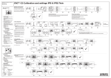
2. WIRING
The following illustration shows the general connection of the NAVpilot-300. For de-
tailed information, see the interconnection diagram at the back of this manual.
12/24 VDC
Reversible Pump
Junction Box
Linear Sensor
Safe Helm System
Event Switch
Rudder Reference Unit
FAP-6112
Gesture Controller
GC-001 (Max. 3 Units)
Processor Unit
FAP-3012
Junction Box
Control Unit
FAP-3011 (Max. 3 Units)
15 VDC
Junction Box
FI-5002
Termination resistor*
1
LTWMC-05BMMT-SL8001
Integrated Heading Sensor
PG-700
CAN bus (NMEA2000)
Device
M12-05BM+BF, 1/2/6 m
FI-70-0600,
6 m
Termination resistor*
1
LTWMC-05BFFTT-SL8001
M12-05BM+BF, 1/2/6 m
M12-05BFFM, 1/2/6 m
M12-05BM+05BF-060, 6 m
DPYC-1.5
1 m
1 m
1 m
1 m
0.6 m
Bluetooth
®
: Standard supply
: Option or local supply
0.6 m
Breaker
EVC System
*
2
*
1
: Termination resistors must be installed at both ends of the backbone.
*
2
: EVC systems compatible with the NAVpilot are as follows:
EVC System Remarks
VOLVO PENTA IPS
YAMAHA Helm Master
YANMAR VC10
SEASTAR SOLUTIONS OPTIMUS
Requires VOLVO IPS gateway (available as an optional extra).
Requires YAMAHA HM gateway (available as an optional extra).
-
The software version of the Main PCM (Pump Control Module)
must be “Rev. T” or later.

2. WIRING
2-2
How to secure and waterproof the cable connections
The connector at the rear of the control unit and all cable connections should be wa-
terproofed and secured after making the connection.
To waterproof and secure each connection, refer to the following procedure.
• Securing and waterproofing the connector at the rear of the control unit
• Securing and waterproofing connections
1) Wrap the connector with the vinyl tape. 2) Wrap the self-vulcanizing tape over the
vinyl tape.
3) Wrap the vinyl tape over the
self-vulcanizing tape.
Vinyl tape Self-vulcanizing tape
Vinyl tape
4) Apply a marine sealant around the base
of the connector.
Marine sealant
Vinyl tape
Self-vulcanizing tape
Vinyl tape
1) Wrap the connector with the vinyl tape.
2) Wrap the self-vulcanizing tape over the
vinyl tape.
3) Wrap the vinyl tape over the self-vulcanizing
tape.
/