Page is loading ...

September 2005 RTAA-SVX01A-EN
© American Standard Inc. 2005
Models RTAA
RTAA-70
RTAA-80
RTAA-90
RTAA-100
RTAA-110
RTAA-125
Installation
Operation
Maintenance
Series R
®
Air-Cooled Rotary Liquid Chillers
Packaged Air-Cooled Chiller,
RTAA 70-125
Remote Evaporator
Air-Cooled Chiller,
RTAA 70-125

2 RTAA-SVX01A-EN
Important
Environmental Concerns!
Scientific research has shown that certain man-made chemicals
can affect the earth’s naturally occurring stratospheric ozone layer
when released to the atmosphere. In particular, several of the
identified chemicals that may affect the ozone layer are
refrigerants that contain Chlorine, Fluorine and Carbon (CFCs) and
those containing Hydrogen, Chlorine, Fluorine and Carbon
(HCFCs). Not all refrigerants containing these compounds have
the same potential impact to the environment. Trane advocates
the responsible handling of all refrigerants—including industry
replacements for CFCs such as and HCFCs and HFCs.
Responsible Refrigerant Practices!
Trane believes that responsible refrigerant practices are important
to the environment, our customers, and the air conditioning
industry. All technicians who handle refrigerants must be
certified. The Federal Clean Air Act (Section 608) sets forth the
requirements for handling, reclaiming, recovering and recycling of
certain refrigerants and the equipment that is used in these
service procedures. In addition, some states or municipalities
may have additional requirements that must also be adhered to
for responsible management of refrigerants. Know the applicable
laws and follow them.
WARNING
Contains Refrigerant!
System contains oil and refrigerant under high pressure. Recover
refrigerant to relieve pressure before opening the system. See
unit nameplate for refrigerant type. Do not use non-approved
refrigerants, refrigerant substitutes, or refrigerant additives.
Failure to follow proper procedures or the use of non-approved
refrigerants, refrigerant substitutes, or refrigerant additives could
result in death or serious injury or equipment damage.
NOTICE: Warnings and Cautions appear at appropriate sections through-
out this literature. Read these carefully.
WARNING: Indicates a potentially hazardous situation which, if not
avoided, could result in death or serious injury.
CAUTION: Indicates a potentially hazardous situation which, if not
avoided, may result in minor or moderate injury. It may also be used to
alert against unsafe practices.
CAUTION: Indicates a situation that may result in equipment or property-
damage only accidents.

RTAA-SVX01A-EN 3
Table of Contents
General Information . . . . . . . . . . . . . . . . . . . . . . . . . . . . . . . . . . . . . . . 5
Unit Identification - Nameplates . . . . . . . . . . . . . . . . . . . . . . . . . . . . . . . . . 5
Nameplates . . . . . . . . . . . . . . . . . . . . . . . . . . . . . . . . . . . . . . . . . . . . . . . . . 5
Unit Inspection . . . . . . . . . . . . . . . . . . . . . . . . . . . . . . . . . . . . . . . . . . . . . . 6
Inspection Checklist . . . . . . . . . . . . . . . . . . . . . . . . . . . . . . . . . . . . . . . . . . 6
Loose Parts Inventory . . . . . . . . . . . . . . . . . . . . . . . . . . . . . . . . . . . . . . . . . 6
Unit Description . . . . . . . . . . . . . . . . . . . . . . . . . . . . . . . . . . . . . . . . . . . . . . 7
Model Number Coding System . . . . . . . . . . . . . . . . . . . . . . . . . . . . . . . . . . 9
Installation — Mechanical . . . . . . . . . . . . . . . . . . . . . . . . . . . . . . . . . . 10
Installation Responsibilities . . . . . . . . . . . . . . . . . . . . . . . . . . . . . . . . . . . . 10
Storage . . . . . . . . . . . . . . . . . . . . . . . . . . . . . . . . . . . . . . . . . . . . . . . . . . . 10
Location Requirements . . . . . . . . . . . . . . . . . . . . . . . . . . . . . . . . . . . . . . . 10
Foundation . . . . . . . . . . . . . . . . . . . . . . . . . . . . . . . . . . . . . . . . . . . . . . . . . 11
Clearances . . . . . . . . . . . . . . . . . . . . . . . . . . . . . . . . . . . . . . . . . . . . . . . . . 16
Rigging . . . . . . . . . . . . . . . . . . . . . . . . . . . . . . . . . . . . . . . . . . . . . . . . . . . 16
Unit Isolation . . . . . . . . . . . . . . . . . . . . . . . . . . . . . . . . . . . . . . . . . . . . . . . 23
Unit Leveling . . . . . . . . . . . . . . . . . . . . . . . . . . . . . . . . . . . . . . . . . . . . . . . 23
Water Piping . . . . . . . . . . . . . . . . . . . . . . . . . . . . . . . . . . . . . . . . . . . . . . . 23
Evaporator Water Piping . . . . . . . . . . . . . . . . . . . . . . . . . . . . . . . . . . . . . . 26
Evaporator Piping Components . . . . . . . . . . . . . . . . . . . . . . . . . . . . . . . . . 27
Entering Chilled Water Piping . . . . . . . . . . . . . . . . . . . . . . . . . . . . . . . . . . 27
Evaporator Drain . . . . . . . . . . . . . . . . . . . . . . . . . . . . . . . . . . . . . . . . . . . . 28
Chilled Water Flow Switch . . . . . . . . . . . . . . . . . . . . . . . . . . . . . . . . . . . . 28
Installation — Remote Evaporator . . . . . . . . . . . . . . . . . . . . . . . . . . . 31
System Configuration and Interconnecting Refrigerant Piping . . . . . . . . . 31
Line Sizing . . . . . . . . . . . . . . . . . . . . . . . . . . . . . . . . . . . . . . . . . . . . . . . . . 38
Example Liquid Line Sizing . . . . . . . . . . . . . . . . . . . . . . . . . . . . . . . . . . . . 39
Suction Line Sizing Steps . . . . . . . . . . . . . . . . . . . . . . . . . . . . . . . . . . . . . 40
Piping Installation Procedures . . . . . . . . . . . . . . . . . . . . . . . . . . . . . . . . . . 44
Refrigerant Sensors . . . . . . . . . . . . . . . . . . . . . . . . . . . . . . . . . . . . . . . . . . 44
Leak Test and Evacuation . . . . . . . . . . . . . . . . . . . . . . . . . . . . . . . . . . . . . 46
Refrigerant and Additional Oil Charge . . . . . . . . . . . . . . . . . . . . . . . . . . . . 46
Relief Valve Venting . . . . . . . . . . . . . . . . . . . . . . . . . . . . . . . . . . . . . . . . . 47
Installation — Electrical . . . . . . . . . . . . . . . . . . . . . . . . . . . . . . . . . . . . 49
General Recommendations . . . . . . . . . . . . . . . . . . . . . . . . . . . . . . . . . . . . 49
Installer-Supplied Components . . . . . . . . . . . . . . . . . . . . . . . . . . . . . . . . . 51
Power Supply Wiring . . . . . . . . . . . . . . . . . . . . . . . . . . . . . . . . . . . . . . . . . 52
Interlock Wiring . . . . . . . . . . . . . . . . . . . . . . . . . . . . . . . . . . . . . . . . . . . . . 52
Low Voltage Wiring . . . . . . . . . . . . . . . . . . . . . . . . . . . . . . . . . . . . . . . . . . 56
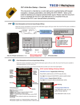
Remote Clear Language Display Installation Procedure . . . . . . . . . . . . . . 62
Operating Principles . . . . . . . . . . . . . . . . . . . . . . . . . . . . . . . . . . . . . . . 66
Refrigeration (Cooling) Cycle . . . . . . . . . . . . . . . . . . . . . . . . . . . . . . . . . . . 66
Oil System Operation . . . . . . . . . . . . . . . . . . . . . . . . . . . . . . . . . . . . . . . . 69
Controls Interface . . . . . . . . . . . . . . . . . . . . . . . . . . . . . . . . . . . . . . . . . 72
Clear Language Display Keypad Overview . . . . . . . . . . . . . . . . . . . . . . . . 72
Select Report Group and Select Settings Group Flowcharts . . . . . . . . . . 74
Diagnostics . . . . . . . . . . . . . . . . . . . . . . . . . . . . . . . . . . . . . . . . . . . . . . . . 93
Operational Features . . . . . . . . . . . . . . . . . . . . . . . . . . . . . . . . . . . . . . . . . 94

4 RTAA-SVX01A-EN
Table of Contents
DIP Switch Settings . . . . . . . . . . . . . . . . . . . . . . . . . . . . . . . . . . . . . . . . . 100
IPC Address . . . . . . . . . . . . . . . . . . . . . . . . . . . . . . . . . . . . . . . . . . . . . . . . 100
Pre-Start Checkout . . . . . . . . . . . . . . . . . . . . . . . . . . . . . . . . . . . . . . . 103
Unit Voltage Power Supply . . . . . . . . . . . . . . . . . . . . . . . . . . . . . . . . . . . . 105
Unit Voltage Imbalance . . . . . . . . . . . . . . . . . . . . . . . . . . . . . . . . . . . . . . . 105
Unit Voltage Phasing . . . . . . . . . . . . . . . . . . . . . . . . . . . . . . . . . . . . . . . . . 106
Water System Flow Rates . . . . . . . . . . . . . . . . . . . . . . . . . . . . . . . . . . . . 107
Water System Pressure Drop . . . . . . . . . . . . . . . . . . . . . . . . . . . . . . . . . . 107
Clear Language Display Set-up . . . . . . . . . . . . . . . . . . . . . . . . . . . . . . . . . 107
Start-Up Procedures . . . . . . . . . . . . . . . . . . . . . . . . . . . . . . . . . . . . . . 108
System Superheat . . . . . . . . . . . . . . . . . . . . . . . . . . . . . . . . . . . . . . . . . . . 111
System Subcooling . . . . . . . . . . . . . . . . . . . . . . . . . . . . . . . . . . . . . . . . . . 111
Unit Shutdown Procedures . . . . . . . . . . . . . . . . . . . . . . . . . . . . . . . . 112
Temporary Shutdown and Restart . . . . . . . . . . . . . . . . . . . . . . . . . . . . . . 112
Extended Shutdown Procedure . . . . . . . . . . . . . . . . . . . . . . . . . . . . . . . . 112
System Restart After Extended Shutdown . . . . . . . . . . . . . . . . . . . . . . . . 113
Periodic Maintenance . . . . . . . . . . . . . . . . . . . . . . . . . . . . . . . . . . . . . 115
Weekly Maintenance . . . . . . . . . . . . . . . . . . . . . . . . . . . . . . . . . . . . . . . . . 115
Monthly Maintenance . . . . . . . . . . . . . . . . . . . . . . . . . . . . . . . . . . . . . . . . 115
Annual Maintenance . . . . . . . . . . . . . . . . . . . . . . . . . . . . . . . . . . . . . . . . . 116
Maintenance . . . . . . . . . . . . . . . . . . . . . . . . . . . . . . . . . . . . . . . . . . . . 119
Coil Cleaning . . . . . . . . . . . . . . . . . . . . . . . . . . . . . . . . . . . . . . . . . . . . . . . 119
Chemically Cleaning The Evaporator . . . . . . . . . . . . . . . . . . . . . . . . . . . . . 120
Water Treatment . . . . . . . . . . . . . . . . . . . . . . . . . . . . . . . . . . . . . . . . . . . . 120
Oil Separator Level Check . . . . . . . . . . . . . . . . . . . . . . . . . . . . . . . . . . . . . 120
Oil Filter Change . . . . . . . . . . . . . . . . . . . . . . . . . . . . . . . . . . . . . . . . . . . . 121
Refrigerant Charging and Recovery . . . . . . . . . . . . . . . . . . . . . . . . . 125
Low Side Repairs . . . . . . . . . . . . . . . . . . . . . . . . . . . . . . . . . . . . . . . . . . . 125
High Side Repair . . . . . . . . . . . . . . . . . . . . . . . . . . . . . . . . . . . . . . . . . . . . 126
Adding Refrigerant . . . . . . . . . . . . . . . . . . . . . . . . . . . . . . . . . . . . . . . . . . 126
Diagnostics . . . . . . . . . . . . . . . . . . . . . . . . . . . . . . . . . . . . . . . . . . . . . 127
Pump Package . . . . . . . . . . . . . . . . . . . . . . . . . . . . . . . . . . . . . . . . . . . 135
Temporary Storage . . . . . . . . . . . . . . . . . . . . . . . . . . . . . . . . . . . . . . . . . . 135
Piping . . . . . . . . . . . . . . . . . . . . . . . . . . . . . . . . . . . . . . . . . . . . . . . . . . . . . 135
Pre-Start Review and Inspection . . . . . . . . . . . . . . . . . . . . . . . . . . . . . . . . 135
Control Panel Features and Options . . . . . . . . . . . . . . . . . . . . . . . . . . . . . 136
Connection Power . . . . . . . . . . . . . . . . . . . . . . . . . . . . . . . . . . . . . . . . . . . 136
Pump Checkout Procedure . . . . . . . . . . . . . . . . . . . . . . . . . . . . . . . . . . . . 137
Control Panel Checkout . . . . . . . . . . . . . . . . . . . . . . . . . . . . . . . . . . . . . . . 137
System Start-up . . . . . . . . . . . . . . . . . . . . . . . . . . . . . . . . . . . . . . . . . . . . . 138
Planned Shutdown . . . . . . . . . . . . . . . . . . . . . . . . . . . . . . . . . . . . . . . . . . 141
Maintenance . . . . . . . . . . . . . . . . . . . . . . . . . . . . . . . . . . . . . . . . . . . . . . . 141
Troubleshooting . . . . . . . . . . . . . . . . . . . . . . . . . . . . . . . . . . . . . . . . . . . . . 142
Unit Wiring . . . . . . . . . . . . . . . . . . . . . . . . . . . . . . . . . . . . . . . . . . . . . 145
Unit Electrical Data . . . . . . . . . . . . . . . . . . . . . . . . . . . . . . . . . . . . . . . . . . 145

RTAA-SVX01A-EN 5
General Information
Unit Identification - Nameplates
When the unit arrives, compare all nameplate data with ordering, submittal,
and shipping information. A typical unit nameplate is shown in Figure 1.
Nameplates
The RTAA outdoor unit nameplates are applied to the exterior of the Control
Panel. A compressor nameplate is located on each compressor.
Outdoor Unit Nameplate
The outdoor unit nameplate provides the following information:
Unit model and size description.
Unit serial number.
Identifies unit electrical requirements.
Lists correct operating charges of R-22 and oil.
Figure 1 Standatd Unit Nameplate
Figure 2 Pump Package Unit Nameplate

6 RTAA-SVX01A-EN
General Information
Lists unit test pressures.
Identifies installation, operation and maintenance and service data
literature.
Lists drawing numbers for unit wiring diagrams.
Pump Package Information - Optional
Compressor Nameplate
The compressor nameplate provides following information:
Compressor model number.
Compressor serial number.
Compressor electrical characteristics.
Utilization range.
Recommended refrigerant.
Unit Inspection
When the unit is delivered, verify that it is the correct unit and that it is
properly equipped. Compare the information which appears on the unit
nameplate with the ordering and submittal information.
Inspect all exterior components for visible damage. Report any apparent
damage or material shortage to the carrier and make a “unit damage”
notation on the carrier's delivery receipt. Specify the extent and type of
damage found and notify the appropriate Trane Sales Office.
Do not proceed with installation of a damaged unit without sales office
approval.
NOTE: If the Remote Evaporator Option is ordered, the remote evaporator
will be shipped in a separate crate.
Inspection Checklist
To protect against loss due to damage incurred in transit, complete the
following checklist upon receipt of the unit.
• Inspect the individual pieces of the shipment before accepting the unit.
Check for obvious damage to the unit or packing material.
• Inspect the unit for concealed damage as soon as possible after delivery
and before it is stored. Concealed damage must be reported within 15
days after receipt.
• If concealed damage is discovered, stop unpacking the shipment. Do not
remove damaged material from the receiving location. Take photos of the
damage. The owner must provide reasonable evidence that the damage
did not occur after delivery.
• Notify the carrier’s terminal of the damage immediately, by phone and by
mail. Request an immediate, joint inspection of the damage with the car-
rier and the consignee.
• Notify the Trane sales representative and arrange for repair. Do not repair
the unit, however, until damage is inspected by the transportation repre-
sentative.
Loose Parts Inventory
Check all the accessories and loose parts which are shipped with the unit
against shipping list. Included in these items will be water vessel drain plugs,
isolators, rigging and electrical diagrams, and service literature, which are
placed inside the control panel and/or starter panel for shipment.

RTAA-SVX01A-EN 7
General Information
Unit Description
The 70 through 125-ton Model RTAA units are helical-rotary type, air-cooled
liquid chillers designed for installation outdoors. The unit has two
compressors and the compressor circuits are completely assembled,
hermetic packages. They are factory-piped, wired, leak-tested, de-hydrated,
and tested for proper operation before shipment. The units are factory
charged with refrigerant and oil.
The RTAA series features Trane's exclusive Adaptive Control™ logic with
Clear Language Display. It monitors the control variables that govern the
operation of the chiller unit. Adaptive Control logic can adjust these variables,
when necessary, to optimize operational efficiencies, avoid chiller shutdown,
and keep producing chilled water. An optional remote display is available to
monitor unit operation from a remote location.
These dual-compressor units feature two independent circuits, one for each
compressor. Compressor unloaders are solenoid actuated. Each refrigerant
circuit is provided with filter drier, sight glass, electronic expansion valve, and
charging valves.
The shell-and-tube type evaporator is manufactured in accordance with ASME
standards. The evaporator is fully insulated and is equipped with water drain
and vent connections. Packaged units have heat tape protection to
-20 F.
NOTE: Packaged units are factory charged with refrigerant and oil. Remote
evaporator units are shipped with a holding charge of nitrogen and a partial
charge of oil.

8 RTAA-SVX01A-EN
General Information
Table 1 General RTAA Mechanical Specifications
Size
70 80 90 100 110 125
Compressor
Quantity 222222
Nominal Size (Tons)(1) 35/35 40/40 50/40 50/50 60/50 60/60
Evaporator
Water Storage (Gallons) 39.8 37.8 34.4 32.1 53.4 45.8
(Liters) 150.6 143.1 130.2 121.5 202.1 173.4
Min. Flow (GPM) 84 96 108 120 132 150
(L/Sec) 5.3 6.1 6.8 7.6 8.3 9.5
Max. Flow (GPM) 252 288 324 360 396 450
(L/Sec) 15.9 18.2 20.4 22.7 25.0 28.4
Refer to Pump Package Section for water storage of Pump and accocated piping.
Condenser
Qty of Coils 444444
Coil Length (Ft)(1) 13/13 13/13 14/13 14/14 17/14 17/17
Coil Height (In) 42 42 42 42 42 42
Number of Rows 222222
Condenser Fans
Quantity (1) 4/4 4/4 5/4 5/5 5/5 5/5
Diameter (In) 303030303030
Total Airflow (CFM) 68,380 68,380 73,365 78,355 82,950 87,550
Nominal RPM 855 855 855 855 855 855
Tip Speed (Ft./Min.) 6715 6715 6715 6715 6715 6715
Motor HP (Ea.) 1.1 1.1 1.1 1.1 1.1 1.1
Min. Starting/Oper. Ambient
Std Unit (Deg. F) 15 15 15 15 15 15
Low Amb. (Deg. F) -10 -10 -10 -10 -10 -10
General Unit
Refrigerant HCFC-22 HCFC-22 HCFC-22 HCFC-22 HCFC-22 HCFC-22
No. of Independent
Refrigerant Circuits 222222
% Min. Load (3) 101010101010
Refrig Charge (Lb) (1) 58/58 61/61 73/61 73/73 98/73 98/98
(Kg) 26/26 27/27 33/27 33/33 44/33 44/44
Oil Charge (Qts) (1.4) 10/10 10/10 12/10 12/12 12/12 12/12
(L) 10.6/10.6 10.6/10.6 12.7/10.6 12.7/12.7 12.7/12.7 12.7/12.7
Notes:
1. Data containing information on two circuits shown as follows: ckt1/ckt2
2. Minimum start-up/operating ambient based on a 5 mph wind across the condenser.
3. Percent minimum load is for total machine, not each individual circuit.
4. Trane Part Change # Oil-31 (see service bulletin SCOM-SB-1)

RTAA-SVX01A-EN 9
General Information
Model Number Coding System
The model number for the unit is comprised of numbers and letters which
represent features of the equipment. Shown on the chart in Figure 3 are
samples of typical unit model numbers, followed by the coding system.
Each position, or group of positions, in the number is used to represent a
feature. For example, in Figure 3, position 8 of the unit model number, Unit
Voltage, contains the number “4”. From the chart, it can be seen that a “4” in
this position means that the unit voltage is 460/60/3.
.
Figure 3 Model Number Coding System:
Model Number RTA A 070 4 Y A0 1 B 1 D A 0
Digit Number
012
Digit Position
1 2 3 4 5 6 7 8 9 0 1 2 3 4 5 6 0
Digit 1-2
Unit Model
RT Rotary Chiller
Digit 3
Unit Type
A Air Cooled
Digit 4
Development Sequence
A First Sequence
Digit 5,6,7
Nominal Capacity
070 70 Nominal Tons
080 80 Nominal Tons
090 90 Nominal Tons
100 100 Nominal Tons
110 110 N ominal Tons
125 125 Nominal Tons
Digit 8
Unit Voltage
D380/60/3
A 200/60/3
C 230/60/3
K 400/50/3
4 460/60/3
5 575/60/3
Digit 9
Compressor Starter Type
Y Y -Delta Closed Transition
X X-Line (Across the Line)
Digit 10, 11
Design Sequence
AO First Sequence (Factory Input)
Digit12
Evaporator Leaving Te m perature
1 Standard 40 to 65 F
2 Low 0 to 39 F
3 Ice-Making 20 to 65 F
Digit 13
Condenser Coil Fin Material
AAluminum
2CompleteCoat dipped coils
4 copper fins
Digit 14
Agency Listing
0 No Agency Listing
3 C-UL Listed
Digit 15
Control Interface
C Deluxe without Communication
D Deluxe with Communication
L LCI-C (LonTalk)
Digit 16
Chilled Water Reset
0 No Chilled Water Reset
1 Based on Return Water Temp
2 Based on Outside Air Temp
Digit 17
Miscellaneous Factory Installed
Options
A Architectural Louvered Panels
B Control Power Transformer
C Convenience Outlet
DLow Ambient Lockout Sensor
F Power Disconnect
GLow Ambient Operation
H Sound Attenuator
JRemote Evaporator
K Coil Protection
M Access Guard
N Neoprene Isolators
P Circuit Breaker
RRemote Display Panel
0Size C 2 HP Pump Package
1 Size D 3 HP Pump Package
2 Size D 5 HP Pump Package
3 Size E 2 HP Pump Package
4 Size E 3 HP Pump Package
5 Size F 5 HP Pump Package
6 Size F 7 HP Pump Package
7 Size G 3 HP Pump Package
8 Size G 5 HP Pump Package

10 RTAA-SVX01A-EN
Installation — Mechanical
Installation Responsibilities
Generally, the contractor must do the following when installing an RTAA unit:
• Install unit on a flat foundation, level (within 1/4” [6 mm] across the
length and width of the unit), and strong enough to support unit loading.
• Install unit per the instructions contained in the Installation-Mechanical
and Installation-Electrical sections of this manual.
• Where specified, provide and install valves in water piping upstream and
downstream of evaporator water connections to isolate the evaporator
for maintenance, and to balance/trim system.
• Furnish and install flow switch to prove chilled water flow.
• Furnish and install pressure gauges in inlet and outlet piping of the evapo-
rator.
• Furnish and install a drain valve to the bottom of the evaporator.
• Supply and install a vent cock to the top of the evaporator.
• Furnish and install strainers ahead of all pumps and automatic modulating
valves.
• Provide and install field wiring.
• Install heat tape and insulate the chilled water lines and any other por-
tions of the system, as required, to prevent sweating under normal oper-
ating conditions or freezing during low ambient temperature conditions.
• Start unit under supervision of a qualified service technician.
For remote evaporator units only
Furnish and install refrigerant piping, liquid line isolation valves, refrigerant,
and oil, per instructions outlined in this manual.
Storage
Extended storage of the outdoor unit prior to installation requires the
following precautionary measures:
Store the outdoor unit in a secure area.
At least every three months (quarterly), check the pressure in the refrigerant
circuits to verify that the refrigerant charge is intact. If it is not, contact a
qualified service organization and the appropriate Trane sales office.
Close the discharge and liquid line isolation valves.
Location Requirements
Noise Considerations
•Refer to Trane Engineering Bulletins for application information on RTAA
chillers.
• Locate the outdoor unit away from sound-sensitive areas.
• If required, install rubber vibration isolators in all water piping and use
flexible electrical conduit.
• Refer to “Unit Isolation”.
• Consult an acoustical engineer for critical applications.

RTAA-SVX01A-EN 11
Installation — Mechanical
Foundation
Provide rigid, non-warping mounting pads or a concrete foundation of suffi-
cient strength and mass to support the outdoor unit operating weight (i.e.,
including completed piping, and full operating charges of refrigerant, oil and
water). Refer to Figure 13 for unit operating weights. Once in place, the
outdoor unit must be level within 1/4” (6.4 mm) over its length and width. The
Trane Company is not responsible for equipment problems resulting from an
improperly designed or constructed foundation.

12 RTAA-SVX01A-EN
Installation — Mechanical
Figure 4 RTAA Rigging and Lifting Weights – Packaged Unit

RTAA-SVX01A-EN 13
Installation — Mechanical
Figure 5 RTAA Rigging and Lifting Weights – Remote Evaporator

14 RTAA-SVX01A-EN
Installation — Mechanical
Figure 6 RTAA Rigging and Lifting Weights –Pump Package Aluminum Fins

RTAA-SVX01A-EN 15
Installation — Mechanical
Figure 7 RTAA Rigging and Lifting Weights –Pump Package Copper Fins

16 RTAA-SVX01A-EN
Installation — Mechanical
Clearances
Provide enough space around the outdoor unit to allow the installation and
maintenance personnel unrestricted access to all service points. Refer to
submittal drawings for the unit dimensions, to provide sufficient clearance for
the opening of control panel doors and unit service. Refer to Figure 8, Figure
9 and Figure 12 for minimum clearances. In all cases, local codes which
require additional clearances will take precedence over these recommenda-
tions.
NOTE: If the outdoor unit configuration requires a variance to the clearance
dimensions, contact your Trane Sales Office Representative. Also refer to
Trane Engineering Bulletins for application information on RTAA chillers.
Additional Location Requirements for Remote Evaporator Only
The Remote evaporator must be installed in a conditioned space, unless:
• The ambient temperature is always greater than 32 F.
• The system circulating liquid is a non-freezing glycol-type solution,
selected for the prevailing ambient temperature. The evaporator is
protected from freezing by properly installed and applied insulation and
heat tape.
CAUTION
Freezing Equipment Damage!
To prevent damage due to freezing, do not install the unit outside
without adequate freeze protection.
The remote evaporator should be mounted on a base of suitable strength to
support the operating weight. Remote evaporator weights and mounting
locations are shown in Figure 10 and Figure 11.
The remote evaporator must be level when installed. Be sure to allow
adequate clearance for water and refrigerant piping connection, performance
of service procedures, reading of gauges and thermometers, and operation
of valves. Space must be allowed at one end of the evaporator to pull tubes,
if required.
Rigging
The Model RTAA chiller should be moved by lifting. Refer to Figure 4 for
typical unit lifting and weights. Refer to the rigging diagram that ships with
each unit for specific “per unit” weight data.
WARNING
Heavy Objects!
Do not use cables (chains or slings) except as shown. Each of the
cables (chains or slings) used to lift the unit must be capable of
supporting the entire weight of the unit. Lifting cables (chains or
slings) may not be of the same length. Adjust as necessary for
even unit lift. Other lifting arrangements may cause equipment or
property-only damage. Failure to properly lift unit may result in
death or serious injury. See details below.

RTAA-SVX01A-EN 17
Installation — Mechanical
Lifting Procedure
CAUTION
Equipment Damage!
To prevent damage do not use a forklift to lift or push the unit.
Position lifting beam so that cables do not contact the unit.
• Install chains and safety chains through the six lifting plates provided on
the unit.
• Attach lifting chains or cables to the chains installed above. Each cable
alone must be strong enough to lift the chiller.
• Attach cables to lifting beam. Total lifting weight, lifting weight distribution
and required lifting beam dimensions are shown in Figure 4 and Figure 5
and on the rigging diagram shipped with each unit. Lifting beam cross-
bars must be positioned so lifting cables do not contact the sides of the
unit.

18 RTAA-SVX01A-EN
Installation — Mechanical
Figure 8 Dimensions and Clearances for RTAA Packaged Unit 70 – 125 Tons

RTAA-SVX01A-EN 19
Installation — Mechanical
Figure 9 Dimensions and Clearances for RTAA with Remote Evaporator 70 – 125 Tons

20 RTAA-SVX01A-EN
Installation — Mechanical
Figure 10 Remote Evaporator Dimensions, RTAA 70 – 125 Tons
/