LIMITED 5 YEAR WARRANTY AND EXCLUSIONS
LevitonwarrantstotheoriginalconsumerpurchaserandnotforthebenetofanyoneelsethatthisproductatthetimeofitssalebyLevitonisfreeofdefectsinmaterialsandworkmanshipundernormalandproperuseforveyearsfromthepurchasedate.Leviton’sonlyobligationistocorrectsuchdefectsbyrepairorreplacement,atitsoption,ifwithinsuchveyearperiodtheproductisreturnedprepaid,withproofofpurchase
date,andadescriptionoftheproblemtoLeviton Manufacturing Co., Inc., Att: Quality Assurance Department, 59-25 Little Neck Parkway, Little Neck, New York 11362-2591.Thiswarrantyexcludesandthereisdisclaimedliabilityforlaborforremovalofthisproductorreinstallation.Thiswarrantyisvoidifthisproductisinstalledimproperlyorinanimproperenvironment,overloaded,misused,opened,abused,oralteredin
anymanner,orisnotusedundernormaloperatingconditionsornotinaccordancewithanylabelsorinstructions.There are no other or implied warranties of any kind, including merchantability and fitness for a particular purpose,butifanyimpliedwarrantyisrequiredbytheapplicablejurisdiction,thedurationofanysuchimpliedwarranty,includingmerchantabilityandtnessforaparticularpurpose,islimitedtove
years. Leviton is not liable for incidental, indirect, special, or consequential damages, including without limitation, damage to, or loss of use of, any equipment, lost sales or profits or delay or failure to perform this warranty obligation.Theremediesprovidedhereinaretheexclusiveremediesunderthiswarranty,whetherbasedoncontract,tortorotherwise.
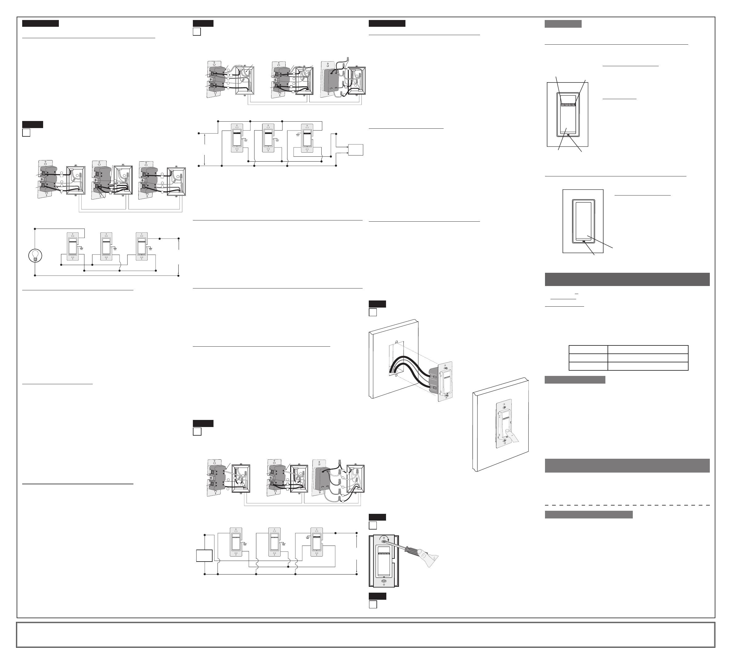
NOTE:Dresswireswithabendasshownindiagraminordertorelievestresswhen
mountingdevice.
• Restorepoweratcircuitbreakerorfuse.
• Seeapplicableoperationsectiontoensuredimmerorswitchisfunctioningproperly.
If lights do not turn ON, refer to the TROUBLESHOOTING section.•
For additional information, contact Leviton’s Techline at
1-800-824-3005 or visit Leviton’s website at www.leviton.com
CoveredbyoneormoreUS&ForeignPatentsandpatentspending
Copyright
©
2007LevitonManufacturingCo.,Inc.
AllRightsIncludingTradeDressRightsReserved
Eco-10™(EcoSeries)isatrademarkandHi-lume
®
isaregisteredtrademarkof
LutronElectronicsInc.
PK-93461-10-00-2A
Restore Power:
Restorepoweratcircuitbreakerorfuse.Installation is complete.
Step 8
Dimmer Remote Mounting:
TURN OFF POWER AT CIRCUIT BREAKER OR FUSE.
Step 7
Installationmaynowbecompletedbytightening
mountingscrewsintowallbox.Attachwallplate.
VP00R Dimmer Remote Operation (Device may be unlighted):
NOTE:ThelightswillturnONatbrightnesssetondimmer’sDIM/BRIGHTbar.The
lightingcanbeswitchedfromeitherthedimmerortheremotelocation.
OPERATION
CLEANING: Clean with a damp cloth. DO NOT use chemical cleaners.
• Lights Flickering
-Lamphasabadconnection.
-Wiresnotsecuredrmlyunderterminalscrewsofdimmerand/orremote.
• Light does not turn ON and Locator LED does not turn ON
-Circuitbreakerorfusehastripped.
-Lampisburnedout.
- Lamp Neutral connection is not wired.
• Intermittent dimmer operation
-Minimumloadisunder40W.
• Remote does not operate lights
-Ensurethattotalwirelengthdoesnotexceed300ft(90m).
-EnsurethatonlyCoordinatingRemotesareusedwithViziarf+™devices
TROUBLESHOOTING
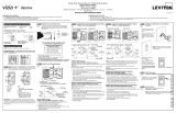
WIRING DIMMER (3-Way wall box with Load connection):
Connect wires per WIRING DIAGRAM as follows:
• GreenorbarecopperwireinwallboxtoGreenterminalscreworGreendimmer
lead.
• Loadwallboxwireidentied(tagged)whenremovingoldswitchtodimmerterminal
screwmarked"RD"ortheReddimmerlead.
• FirstTravelerLineHottodimmerterminalscrewmarked"BK"ortheBlackdimmer
lead.
• RemoveRedinsulatinglabelfromterminalscrewmarked"YL/RD"ortheYellow/
Red dimmer lead.
• SecondTravelerwallboxwire(note color as above) to dimmer terminal screw
marked"YL/RD"ortheYellow/Reddimmerlead.Thistravelerfromthedimmer
mustgototheterminalscrewontheremotemarked"YL/RD".
• Proceed to Step 6.
Step 5a cont’d
4-Way Wiring with Matching Remote (w/LEDs)
Application:
BK
RD
YL/RD
3
T e rminal
Screw marked
Red (RD)
T e rminal
Screw marked
Y e llow/Red
(YL/RD)
Coordinating Remote
(3-Way Wall box from Step 2)
Coordinating Remote
(4-Way Box from Step 2)
Dimmer
(3-Way Wall Box from Step 2)
6
2
1
5
4
BK
RD
YL/RD
T e rminal
Screw marked
Black (BK)
T e r m in a l
Scr e w m a r ke d
Red ( RD )
T e rminal
Screw marked
Y e llow/Red
(YL/RD)
2
4
3
5
1
BK
RD
YL/RD
2
4
3
5
1
Hot (Black)
Neutral (White)
Load
Dimmer
Coordinating Remote
(no LEDs)
Coordinating Remote
(no LEDs)
YL/RD
YL/RD
YL/RD
RD
RD
WHWH
RD
BK
BK
BK
Black
not used
White
Line
120VAC, 60Hz
not used
not used
Green
Ground
Green
Ground
Green
Ground
Step 5b
4-Way Wiring with Coordinating Remote (no LEDs)
Application:
NOTE:IncandescentandMagneticLowVoltageinstallationsonly.
NOTE: Screw terminal dimmer depicted.
WIRING COORDINATING REMOTE (4-Way box):
Connect wires per WIRING DIAGRAM as follows:
NOTE:Maximumwirelengthfromdimmertolastremoteis300ft(90m).
• GreenorbarecopperwireinwallboxtoGreenterminalscrew.
• FirstTravelerandThirdTravelerwallboxwire(note wire colors) to terminal
screwmarked"RD".Thesetravelersfromtheremoteinthe4-wayboxmustgoto
theterminalscrewonthedimmermarked"RD"orReddimmerlead,andtothe
terminalscrewmarked"RD"oftheremainingremoteinthe3-waybox.
• SecondTraveler(tagged)andFourthTraveler(tagged)wallboxwire(note wire
colors)toterminalscrewmarked"YL/RD".Thesetravelersfromtheremotein
the4-wayboxmustgototheterminalscrewonthedimmermarked"YL/RD"or
theYellow/Reddimmerlead,andtotheterminalscrewmarked"YL/RD"ofthe
remainingremoteinthe3-waybox.
• Remoteterminalscrewmarked"WH"shouldhaveWhiteinsulationlabelafxed.
NOTE:Ifinsulatinglabelisnotafxedtoterminalscrewmarked"WH",use
electricaltapetocover.Remoteterminalscrewmarked"BK"isnotused.Use
electricaltapetocover.
WIRING DIMMER (3-Way box):
Connect wires per WIRING DIAGRAM as follows:
NOTE:WhenusingthecoordinatingremotewithoutLEDs,thedimmercanbe
installedoneithertheLineorLoadsideofthe3-waycircuit.
NOTE:Maximumwirelengthfromdimmertoallinstalledremotescannotexceed
300ft(90m).
• GreenorbarecopperwireinwallboxtoGreenterminalscreworGreendimmer
lead.
• LineHot(common)wallboxwireidentied(tagged)whenremovingoldswitchto
dimmerterminalscrewmarked"BK"orBlackdimmerlead.
• FirstTravelerwallboxwiretodimmerterminalscrewmarked"RD"orReddimmer
lead (note wire color as above).Thistravelerfromthedimmermustgotothe
terminalscrewontheremotemarked"RD".
• RemoveRedinsulatinglabelfromterminalscrewmarked"YL/RD"orYellow/Red
dimmer lead.
• SecondTravelerwallboxwiretodimmerterminalscrewmarked"YL/RD"orYellow/
Red dimmer lead (note wire color as above).Thistravelerfromthedimmermust
gototheterminalscrewontheremotemarked"YL/RD".
WIRING COORDINATING REMOTE (3-Way box):
Connect wires per WIRING DIAGRAM as follows:
NOTE:Maximumwirelengthfromdimmertolastremoteis300ft(90m).
• GreenorbarecopperwireinwallboxtoGreenterminalscrew.
• Loadwallboxwireidentied(tagged)whenremovingoldswitchtoterminalscrew
marked"BK".
• FirstTravelerwallboxwire(note color as above)toterminalscrewmarked"RD".
Thistravelerfromtheremotemustgototheterminalscrewonthedimmermarked
"RD"ortheReddimmerlead.
• SecondTravelerwallboxwire(note color as above)toterminalscrewmarked
"YL/RD".Thistravelerfromtheremotemustgototheterminalscrewonthe
dimmermarked"YL/RD"ortheYellow/Reddimmerlead.
• Remoteterminalscrewmarked"WH"shouldhaveWhiteinsulationlabelafxed.
NOTE:Ifinsulatinglabelisnotafxedtoterminalscrewmarked"WH",use
electricaltapetocover.
• Proceed to Step 6.
4
3
5
Black
Green
White
Red
Yellow/Red
1
2
Control
(3-Way Wall Box from Step 2)
BK
RD
YL/RD
Matching Remote
(3-Way Wall box from Step 2)
Matching Remote
(4-Way Wall box from Step 2)
4
3
5
Additional
Neutral Wire
T e rminal
Screw marked
Black (BK)
T e rminal
Screw marked
White (WH)
6
2
1
T e rminal
Screw marked
White (WH)
Additional
Neutral Wire
BK
RD
YL/RD
4
3
1
2
5
T e rminal
Screw marked
Black (BK)
T e rminal
Screw marked
Y e llow/Red
(YL/RD)
T e rminal
Screw marked
Y e llow/Red
(YL/RD)
Hot (Black)
Neutral (White)
Control
Matching Remote
(w/LEDs)
Matching Remote
(w/LEDs)
YL/RD
YL/RD
Yellow/Red
Red
WH
White
WH
BK
BK
Black
Line
120VAC, 60Hz
Black
White
Load
Green
Ground
Green
Ground
Green
Ground
4-Way Wiring with Matching Remote (w/LEDs) for Controls
with Neutral Connection Application:
NOTE:ElectronicLowVoltage,Mark10™,QuietFanSpeedandElectronic
Switch installations only.
NOTE: Dimmer is depicted.
Step 5c
NOTE:ThecontrolmustbeinstalledinawallboxthathasaLoadconnection.The
matchingremotemustbeinstalledinawallboxwithaLineHotconnectionandaNeutral
connection.ANeutralwiretothematchingremoteneedstobeaddedasshown.
Ifyouareunsureaboutanypartoftheseinstructions,consultaqualiedelectrician.
NOTE:Maximumwirelengthfromcontroltoallinstalledremotescannotexceed
300ft(90m).
WIRING MATCHING REMOTE (4-Way wall box with Line Hot connection):
Connect wires per WIRING DIAGRAM as follows:
• GreenorbarecopperwireinwallboxtoGreenterminalscrew.
• FirstTravelerandThirdTravelerwallboxwiretoremoteterminalscrewmarked"BK"
in4-waybox,andtoterminalscrewmarked"BK"oftheremainingremotein3-way
box.
• SecondTraveler(tagged)andFourthTraveler(tagged)wallboxwirefromcontrolin
3-wayboxtoremoteterminalscrewmarked"YL/RD"in4-wayboxandtoterminal
screwmarked"YL/RD"oftheremainingremotein3-waybox(note wire colors).This
travelerfromtheremotesmustgototheterminalscrewmarked"YL/RD"or
Yellow/Redcontrollead.
• LineNeutralwallboxwiretoremoteterminalscrewmarked"WH".
WIRING MATCHING REMOTE (3-Way wall box with Line Hot connection):
Connect wires per WIRING DIAGRAM as follows:
• GreenorbarecopperwireinwallboxtoGreenterminalscrew.
• LineHot(common)wallboxwireidentied(tagged)whenremovingoldswitchand
FirstTravelerwallboxwiretocontrolterminalscrewmarked"BK"orBlackdimmer
lead.
• SecondTravelerwallboxwirefromcontroltoremoteterminalscrewmarked"YL/RD"
(note wire color as above).Thistravelerfromtheremotemustgototheterminal
screwmarked"YL/RD"orYellow/Reddimmerlead.
• LineNeutralwallboxwiretoremoteterminalscrewmarked"WH".
WIRING CONTROL (3-Way wall box with Load connection):
Connect wires per WIRING DIAGRAM as follows:
• GreenorbarecopperwireinwallboxtoGreenterminalscreworGreendimmerlead.
• Loadwallboxwireidentied(tagged)whenremovingoldswitchtoterminalscrew
marked"RD"orRedcontrollead.
• FirstTravelerLineHottoterminalscrewmarked"BK"orBlackcontrollead.
• RemoveRedinsulatinglabelfromterminalscrewmarked"YL/RD"orYellow/Red
control lead.
• SecondTravelerwallboxwire(note color as above)toterminalscrewmarked
"YL/RD"orYellow/Redcontrollead.Thistravelerfromthecontrolmustgotothe
terminalscrewontheremotemarked"YL/RD".
• LineNeutralwallboxwiretoterminalscrewmarked"WH"orWhitecontrollead.
• Proceed to Step 6.
4-Way Wiring with Coordinating Remote (no LEDs) for Controls
with Neutral Connection Application:
NOTE:ElectronicLowVoltage,Mark10™,QuietFanSpeedand
Electronic Switch installations only. NOTE: Dimmer is depicted.
Step 5d
WIRING CONTROL (3-Way box):
Connect wires per WIRING DIAGRAM as follows:
NOTE:ThecontrolmustbeinstalledinawallboxthathasaLineHotconnection.
NOTE:Maximumwirelengthfromcontroltoallinstalledremotescannotexceed300ft
(90m).
• GreenorbarecopperwireinwallboxtoGreenterminalscreworGreencontrollead.
• LineHot(common)wallboxwireidentied(tagged)whenremovingoldswitchto
terminalscrewmarked"BK"orBlackcontrollead.
• FirstTravelerwallboxwiretoterminalscrewmarked"RD"orRedcontrollead(note
wire color as above).
• RemoveRedinsulatinglabelfromterminalscrewmarked"YL/RD"orYellow/Red
control lead.
• SecondTravelerwallboxwiretoterminalscrewmarked"YL/RD"orYellow/Red
control lead (note wire color as above).Thistravelerfromthecontrolmustgotothe
terminalscrewontheremotemarked"YL/RD".
• LineNeutralwallboxwiretoterminalscrewmarked"WH"orWhitecontrollead.
WIRING COORDINATING REMOTE (3-Way box):
Connect wires per WIRING DIAGRAM as follows:
NOTE:"BK"and"RD"terminalsoncoordinatingremoteareunused.Tightenboth
screws.
NOTE:Maximumwirelengthfromcontroltolastremoteis300ft(90m).
• GreenorbarecopperwireinwallboxtoGreenterminalscrew.
• Loadwallboxwireidentied(tagged)whenremovingoldswitchtoFirstTraveler(note
color as above).
• SecondTravelerwallboxwire(note color as above)toterminalscrewmarked
"YL/RD".Thistravelerfromtheremotemustgototheterminalscrewmarked"YL/RD"
orYellow/Redcontrollead.
• RemoveWhiteinsulatinglabelfromterminalscrewmarked"WH".
• LineNeutralwallboxwiretoterminalscrewmarked"WH".
• Proceed to Step 6.
BK
RD
YL/RD
3
5
1
2
3
4
5
Black
White
Green
Red
Yellow/Red
2
1
1
4
4
3
5
2
T e rminal
Screw marked
White (WH)
T e rminal
Screw marked
White (WH)
T e rminal
Screw marked
Y e llow/Red
(YL/RD)
T e rminal
Screw marked
Black (BK)
T e rminal
Screw marked
Y e llow/Red
(YL/RD)
T e rminal
Screw marked
Black (BK)
Coordinating Remote
(3-Way Wall box from Step 2)
Coordinating Remote
(4-Way Box from Step 2)
Control
(3-Way Wall Box from Step 2)
6
BK
RD
YL/RD
Hot (Black)
Neutral (White)
Control
Coordinating Remote
(no LEDs)
Coordinating Remote
(no LEDs)
YL/RD
YL/RD
YL/RD
RD
White
Red
Black
Black
BKWH
WH
White
Line
120VAC, 60Hz
RD
not used
not used
not used
not used
BK
Load
Green
Ground
Green
Ground
Green
Ground
WIRING COORDINATING REMOTE (4-Way box):
Connect wires per WIRING DIAGRAM as follows:
NOTE:"BK"and"RD"terminalsoncoordinatingremoteareunused.Tightenboth
screws.
NOTE:Maximumwirelengthfromdimmertolastremoteis300ft(90m).
• GreenorbarecopperwireinwallboxtoGreenterminalscrew.
• ConnectFirstTravelerwallboxwiretoThirdTravelerwallboxwire(note wire colors)
toterminalscrewmarked"RD"ofremotein4-waybox,andtoterminalscrewmarked
"RD"oftheremainingremotein3-waybox.
• ConnectSecondTravelerandFourthTravelerwallboxwire(note wire colors) to
terminalscrewmarked"YL/RD"ofremotein4-waybox,andtoterminalscrewmarked
"YL/RD"oftheremainingremotein3-waybox.
Thistravelerfromtheremotesmustgototheterminalscrewmarked"YL/RD"or
Yellow/Redcontrollead.
• RemoveWhiteinsulatinglabelfromterminalscrewmarked"WH".
• LineNeutralwallboxwiretoterminalscrewmarked"WH".
Step 5d cont’d
Testing your Remote prior to completely
mounting in wall box:
Step 6
Push Pad (Default settings)
Turn ON from OFF position:
Tap–LightsturnONtopresetlevel.
PressandHold–LightsturnONtofullbright.
Turn OFF from ON position:
Tap–LightsturnOFF.
DIM/BRIGHT Bar
BRIGHTEN:
PressrighthalfofDIM/BRIGHTBar–Lightsbrightento
desiredlevel.
DIM:
PresslefthalfofDIM/BRIGHTBar–Lightsdimto
desiredlevel.
Ifyoucontinuetohold,thelightswillDIMtominimum
levelandthenturnOFF.
Intheeventofpoweroutageorinterruptionthelightswill
resettothelastlevelwhenpowerisrestored.
DIM/BRIGHT
Bar
Push Pad
Locator
Light
LED
Brightness
Display
VP0SR Switch Remote Operation (Device may be unlighted):
Thelightingcanbeswitchedfromeitherthedimmerortheremotelocation.
Push Pad (Default settings)
Turn ON from OFF position:
Tap–LightsturnONtopresetlevel.
Turn OFF from ON position:
Tap–LightsturnOFF.
Intheeventofpoweroutageor
interruption the lights will reset to the last
levelwhenpowerisrestored.
Push Pad
Locator
Light
ThisequipmenthasbeentestedandfoundtocomplywiththelimitsforaClassB
DigitalDevice,pursuanttoPart15oftheFCCRules.Theselimitsaredesignedto
providereasonableprotectionagainstharmfulinterferenceinaresidentialinstallation.
Thisequipmentgenerates,uses,andcanradiateradiofrequencyenergyand,ifnot
installedandusedinaccordancewiththeinstructions,maycauseharmfulinterference
toradiocommunications.However,thereisnoguaranteethatinterferencewillnot
occurinaparticularinstallation.Ifthisequipmentdoescauseharmfulinterferenceto
radioortelevisionreception,whichcanbedeterminedbyturningtheequipmentOFF
andON,theuserisencouragedtotrytocorrecttheinterferencebyoneormoreofthe
followingmeasures:
• ReorientorrelocatethereceivingAntenna.
• Increasetheseparationbetweentheequipmentandthereceiver.
• Connecttheequipmentintoanoutletonacircuitdifferentfromthattowhichthe
receiverisconnected.
• Consultthedealeroranexperiencedradio/tvtechnicianforhelp.
FCC COMPLIANCE STATEMENT
• Positionallwirestoprovideroomin
outletwallboxfordevice.
• Ensurethattheword"TOP"isfacingup
onthedevicestrap.
• Partiallyscrewinmountingscrewsin
wallboxmountinghole.
VP00R-1L ADVANCED PROGRAMMING FEATURES
FOR USE WITH VIZIA RF +™ ONLY
Definition of A Modes
A) LEDOptions:SetssingleLED(default)orLEDBartodisplaytheloadstatus.
Program Mode A
To enter Program Mode A:
Press and hold the Push Pad and then the righthalfoftheDIM/BRIGHTBar
(
^
)
for5
secondsuntilallLEDsblink.
UponreleasingthePushPadLocatorLEDwillblinkoncepersecondtoindicate
Program Mode A, LED Options.TochangetheLED Options settings, release
thePushPad.Thissettingwillautomaticallybesavedandthedevicewillexit
Programming Mode.
LED Options
LED Brightness/Fan Speed Display
Default Single LED
Firsttoggle LEDBar