Lutron Electronics VT-AD Installation guide
- Category
- Dimmers
- Type
- Installation guide
This manual is also suitable for
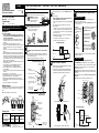
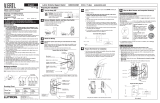
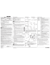
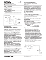
Lutron Electronics VTELV-600M is an Electronic Low-Voltage Dimmer designed to control the primary side of electronic transformer-supplied low-voltage lighting, incandescent lamps, or a combination of the two. It can be used in both single-pole and multi-location installations, with up to four Companion Dimmers (VT-AD) in a 3-way/4-way circuit. The Dimmer features a Front Accessible Service Switch (FASS) for easy troubleshooting and maintenance. It also includes a Derating Chart to help determine the maximum load capacity based on the number of controls in a multigang installation.
Lutron Electronics VTELV-600M is an Electronic Low-Voltage Dimmer designed to control the primary side of electronic transformer-supplied low-voltage lighting, incandescent lamps, or a combination of the two. It can be used in both single-pole and multi-location installations, with up to four Companion Dimmers (VT-AD) in a 3-way/4-way circuit. The Dimmer features a Front Accessible Service Switch (FASS) for easy troubleshooting and maintenance. It also includes a Derating Chart to help determine the maximum load capacity based on the number of controls in a multigang installation.


-
 1
1
-
 2
2


Lutron Electronics VT-AD Installation guide
- Category
- Dimmers
- Type
- Installation guide
- This manual is also suitable for
Lutron Electronics VTELV-600M is an Electronic Low-Voltage Dimmer designed to control the primary side of electronic transformer-supplied low-voltage lighting, incandescent lamps, or a combination of the two. It can be used in both single-pole and multi-location installations, with up to four Companion Dimmers (VT-AD) in a 3-way/4-way circuit. The Dimmer features a Front Accessible Service Switch (FASS) for easy troubleshooting and maintenance. It also includes a Derating Chart to help determine the maximum load capacity based on the number of controls in a multigang installation.
Ask a question and I''ll find the answer in the document
Finding information in a document is now easier with AI
Related papers
-
 Lutron Electronics VT-AD Installation guide
-
 Lutron Electronics Maestro User manual
-
 Lutron Electronics RadioRA2 RRD-H2RLD Installation guide
-
 Lutron Electronics SC-1PS-DS User manual
-
skylark SFSQ-F-GR User manual
-
 Lutron Electronics AYFSQ-F-WH User manual
-
 Lutron Electronics DESIGNER-STYLE WIRED MAESTRO DIMMERS User manual
-
 Lutron Electronics Spacer System SPS-300LD Installation guide
-
AMX Maestro ALD-HD-RS User manual
-
 Lutron Electronics N-600 Installation guide


Other documents
-
Ortech DMD-ELV User manual
-
HQ CX WALLBOX Datasheet
-
Lutron MSCELV-600M-SI Installation guide
-
-
-
Sitecom TB-009 Datasheet
-
Lutron MSCL-OP153M-ST User guide
-
Maestro MAELV-600-LA User manual
-
Smart Wallbox A0009069306 User manual
-