Page is loading ...

1
UNIVERSAL ANEMOMETER INTERFACE
I
NSTALLATION MANUAL
Withthisinterface,someanemometersnotmanufacturedbyDavisInstruments
canbeusedwiththeVantagePro2.Non‐DavisanemometersmusthaveAC
voltageoutputsignals.ThefrequencyoftheACsignalmustbelinearlypropor‐
tionaltothewindspeed.
Thisin
terfacehasbeentestedwithR.M.Younganemometers,modelnumber
05103;andwithNRGanemometers,model1900NRG#40CorMAX40.How‐
ever,theinterfaceisnotlimitedtotho
seproducts.
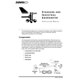
Components
TheUniversalAnemometerInterfaceincludesthefollowingcomponentsand
mountinghardware:
1/4" Flat Washers
1/4" Lock Washers
1/4" Hex Nuts
3-Volt
Lithium
Battery
U-Bolts
1/4" x 1-1/2" Lag Screws
8" Cable Ties
Interface Shelter
#6 x 1/2" (3.5 x 12 mm)
Self-Threading Screw
#6 Washer
Cable Clamp
ISS Cable
(4-Conductor Cable)
Anemometer Cable
(6-Conductor Cable)

2
Tools for Setup
Inaddition,youwillneedsomeorallofthefollowingmaterials:
•Adjustablewrenchor7/16ʺwrench
•Compassorlocalareamap(toadjustwinddirection,ifneeded)
•Drilland3/16ʺ(5mm)drillbit(ifmountingonaverticalsurface)
•Carpenter’slevel(ifmountingonaverticalsurface)
If you are installing a Davis Integrated Sensor Suite (ISS) or
Anemometer Transmitter Kit and the non-Davis anemometer at
the same time:
InstallyourISSfirst,followingtheinstructionsintheinstallationmanual.How‐
ever,skipthestepsthatdirectyoutoconnecttheanemometercabletotheSIM.
Whenyouarereadytomounttheanemometer(fortheISS,afteryouhave
mountedtheraincollectorsideoftheISS),followtheinstructionsinthismanual
startingwith
“MounttheNewAnemometer”onpage4.
Installation Steps
Thefollowingisanoutlineofthestepsnecessarytoinstallananemometerwith
theUniversalAnemometerInterface.Thesestepsareusedassectionheadings
inthismanualandareexplainedingreaterdetailintheappropriatesection.
•Removetheoldanemometerfromitscurrentlocationanddisconnectthe
anemometerfromtheISStransmitter(ifnecessary)
•Mountthenewanemometer
•Mounttheinterfaceshelter
• Connecttheanemometercabletotheanemometer
•Insertthebatteryintheinterfaceshelter
• Connecttheanemometercabletotheinterface
• ConnecttheISScabletotheinterface
• ConnecttheISScabletotheISSorAnemometerTransmitterKitSIM
•Configuretheconsole

3
If you are replacing an already mounted and installed anemome-
ter:
Remove the old anemometer from its current location
Thefollowingtwostepsassume thatyourISS,withstandardanemometer,is
alreadymounted.
Disconnect the old anemometer from the ISS transmitter
OpentheVantagePro2SIMBoxandunplugtheanemometercablefromthe
receptaclelabeledWINDontheSIM.Removethefoaminsertandthenguide
thecableoutofthebox.Whenfinished,makesuretoreplacethefoaminsert
ensuringthattheaccessportisfilledandfreeofanyvo
ids.Ifyouarediscon‐
nectingananem
ometertransmitterkit,guidetheanemometercablethrough
andfreeitfromthegrommet.
If your ISS and anemometer are mounted as
a single unit (both together on a pole)
Unfastentheanemometer:
1. Removetheblackraincollectorco
nefromitsbase
byrotatingconecounter‐clockwiseuntilitslatches
lineupwithopeningsinthebaseandyoucanliftit
off.Itismucheasiertoreachthehexnutswitha
wrenchifyouremovetheraincollectorconefirst.
2. Usinganadjustablewrenchor7/
16ʺwrench,removethehexnutsandwash‐
ersholdingtheanemomet
er’splasticmountingbaseonthepole.Settheane‐
mometerdo
wnforamoment.
3. Removethehexnutsan
dwashersholdingtheraincollectorsideonthepole.
RetrievetheU‐boltthatwasholdingtheanemometer.
4. Usingthew
ashersandhexnuts,fastentheraincollectorsidebackontothe
pole.Flatwashergoesonfirst,thenlockwasher,thenhexnut.
5. Puttheraincollec
torconebackon.Rotatetheconeclockwiseuntilthelatches
slideintoplace.
If your old anemometer is mounted by itself
Unfastenitbyusinganadjustablewrenchor7/16ʺwrenchtoremovethehex
nutsorlagscrews.

4
Mount the New Anemometer
Refer to the manufacturer’s directions to mount the new anemometer.
However,keepthefollowingfactorsinmindasyouchoosealocationforyour
anemometerandtheinterfaceshelter:
•Mounttheanemometeratleast4ʹ(1.2m)abovetherooflineforaccuratewind
readings.
•Mounttheinterfaceshel
ternearby,withthesolarpanelfacingthesun.Inthe
NorthernHemisphere,positionthetransmittershelterwithsolarpanelfacing
southformaximumsunexposure.(IntheSouthernHemisphere,positionthe
shelterwithsolarpanelfacingnorth.)
Mount the Interface Shelter
Mounting on a pole
1. Whileholdingthe
shelteragainstthe
pole,placeaU‐bolt
aroundthepoleand
throughthetwo
holesonatthetop
oftheshelter.
Flat
Washer
Lock
Washer
Hex
Nut
U-Bolt
2. Placeaflatwasher,
alockwasheranda
hexnutoneachof
theboltends.
3. Usinganadjustable
wrenchor7/16ʺ
wrench,tighte
nthe
nuts.
4. PlacethesecondU‐boltaroundthepoleandthroughthetw
oholesatthebot‐
tomoftheshelter
.Putaflatwasher,alockwasher,andahexnutoneachbolt
end,andtightenthehexnuts.
Note: Remember to position the shelter so the solar panel has maximum exposure to the sun.

5
Mounting on a vertical surface
1. Witha3/16ʺ(5mm)drillbit,drilltwoholesapproximately2ʺ(50mm)apart.
Useacarpenter’sleveltoensuretheholesarelevel.
2. Drilltw
omoreholes
7‐1/32ʺ(17.9cm)
belowtheupper
holes.
Flat
Washer
Lag
Screw
3. Insertthe1/4ʺx1‐1/2ʺ
lagscrewsthrough
theflatwashers,and
throughtheholesat
thetopoftheshelter
intothepost.Using
anadjustablewrench
or7/16ʺwrench,
tightenthelag
screws.
4. Insertthe1/4ʺx1‐1/2ʺ
lagsc
rewsthroughtheflatwashers,andthroughtheholesatthebottomof
theshelterintothepost.Usinganadjustablewrenchor7/16ʺwrench,tighten
thelagscrews.
Note: Remember to position the shelter so the solar panel has maximum exposure to the sun.

6
Insert the Battery
1. Insertthe3‐voltlithiumbatteryintothebatteryholder,matchingthe“+”sign
onthebatterywiththe“+”signinsidetheinterfaceshelter.
Note: It will take approximately one minute for the capacitor to charge and the unit to begin functioning.
Connect the Cable to the New Anemometer
R. M. Young 05103:
1. Openthejunctionboxontheanemometerandcutthejumperwire.(Its
locationismarked“JUMPFORCOMMONREF”.)
2. Unscrewthesealingnutonthestrainrelief.
3. Oneendofthe6‐connectorcablehasfivecoloredwires,tinnedandstripped,
andawhite(unused)wire.Feedthisendofthecablethroughthesealingnut
andthestrainreliefintothejunctionbox.
4. Connectthewirestothenumberedterminalstripasfollows:
Black . . . . . . .2
Red . . . . . . . . .3
Green . . . . . . .4
Yellow . . . . . .5
Blue . . . . . . . .6
White . . . . . . .unused
5. Replacethejunctionboxcoverandsealingnut.
NRG#40C/MAX40:
1. Useonlytheblackandbluewires.Connecttheblackwiretothe
anemometer’sblackgroundwireandthebluewiretotheanemometer’s
whitesignalwire.
2. Connecttheredandgreenwirestogether.

7
Connect the Anemometer Cable to the Interface
3-Volt Lithium Battery
“OUT”
RJ Jack
Anemometer
Selector Jumper
(labeled “P2”)
IN OUT
Solar Panel Cable
Square Black
Grommets
Cable Clamp
Mount
ISS Cable
Cable Clamp
Anemometer
Cable
“IN”
RJ Jack
P2
3
2
1
1. Opentheinterfaceshelter.Feedthelooseendofthe6‐conductoranemometer
cableupthroughthesquareblackgrommetatthebaseoftheshelter.(The
Davisshelterhastwoofthesegrommetstoprovideweather‐resistant
entrancesforcables.Inthiscase,usethegrommetontheright.Youcanalso
rem
ovethegrommet,threadthecablethroughitandthenreplacethe
grommetintheshelterifthatiseasier.)
2. PlugtheendofthecableintotheRJja
cklabeled“IN.”
3. Locatetheanemome
terselectorjumperandmovetheshunttothecorrect
pins,asillustrated
•ShuntP2pins1&2ifyouranemometer’sAC
outputsignalhasafrequencyof90Hzwhen
thewindspeedis19.7mphor8.8m/s;
transferfunct
ion:mph=Hzx0.219.(e.g.
R.M.Yo
ung05103).
R.M. Young
(Pins 1 & 2 shunted)
Other
(Pins 2 & 3 shunted)
3
2
1
3
2
1
•ShuntP2pins2&3ifyo
uareusinganother
anemometerthatisnotanR.M.Youngor
doesnothavethesametransferfunctionas
theR.M.Young(seeabove).

8
Connect the ISS Cable to the Interface
1. Feedoneendofthe4‐conductorISScableintothesamegrommetasthe6‐
conductorcable.
2. PlugitintotheRJjacklabeled“OUT
.”
3. Securebo
thcablesinsidewiththecableclamp.Placethecableclampover
bothcablesbetweenthegrommetandthereceptacle.Securethecableclamp
totheshelterbythreadingtheprovided#6screwthroughthewasherand
cableclampandthenscrewingitintothecableclampmountinsidethehous‐
ing.(Se
eillustrationonpage7.)
4. Closetheshelter
,beingcarefulnottopinchthesolarpanelcable.
Connect the ISS cable to the SIM
For a Vantage Pro2 ISS
ThisillustrationshowstheSensorInterfaceModule,or“SIM”,insidethe
VantagePr
o2transmittershelter.
Foam
Insert
Sensor
Interface
Module
(SIM)
ISS
Cable
1. OpentheVantagePro2transmittershelter.
2. Pullthefoaminsertou
tofthecableaccessportinbetweenthecablesandset
thefoamaside.
3. InserttheISScablethr
oughthecableaccessportwiththeconnectorlever
down.
4. Firmlyi
nserttheendoftheISScableintotheconnectorlabeledWIND.The
leverclicksintoplace.

9
5. Makesurethatthecableslieflatonthebottomofthecableaccessport.
6. Firmlyi
nsertthefoaminbetweenthecablesandthetopofthecableaccess
port,takingcaretoensurethatthefoamsealstheaccessportentirely,leaving
noholesorgapslargeenoughforweatherorinsects.
Note: Refer to your Vantage Pro2 ISS Installation Manual for more information.
For an Anemometer Transmitter Kit
1. ThisillustrationshowstheSensorInterfaceModule,or“SIM”,insidethe
VantagePro2transmittershelter.
ISS
Cable
Square Black Grommets
SENSOR SENSOR
INTERFACE INTERFACE
MODULE MODULE
UV UV SUN SUN
RAIN RAIN WIND WIND
TEMP TEMP
HUM HUM
Cable Clamp
Cable Clamp
Mount
1. PushtheendoftheISScableupthroughthesquareblackgrommetintothe
transmittershelter.EveryDavisshelterhastwoofthesegrommetstoprovide
weather‐resistantentrancesforcables.Inthiscase,usethegrommetonthe
right.Youcanalsoremovethegrommet,threadthecablethroughitandthe
n
replacethegrommetintheshelterifthatiseasierforyou.Plugtheendofthe
ISScableintothereceptaclelabeledWINDontheSIM.
2. Placethecableclampov
ertheISScablebetweenthegrommetandtherecep‐
tacle.Sec
urethecableclamptotheshelterbythreadingtheprovided#6
screwthroughthewasherandcableclampandthenscrewingitintothecable
clampmountinsidethehousing.
Note: Refer to your Anemometer Transmitter Kit Manual for more information.

10
Configure the Console
Note: If your are not using an R.M. Young anemometer, you must use a Vantage Vue console. This con-
sole allows for the special calibration needed.
Vantage Pro2 Console
IfyouranemometerrequiredthatP2pins1&2beshunted(e.g.R.M.Young,see
page7)followtheseinstructionstoconfigureyourVantagePro2console:
1. EnterSetupModebypressingDONEandthe“‐”keyatthesametime.
2. PressandreleasetheDONEkeytoscrollthroughthesetupscreensuntil
WINDCUPSIZEappears.Pressthe“+”and“‐”keystoscrollthroughthe
windcupoptionsandselect“OTHER.”
Note: Early firmware versions may not have the OTHER option. You can update your firmware at
www.davisnet.com/support.
3. PressandholdDONEtoreturntothecurrentweatherscreen.
Vantage Vue Console
1. EnterSetupbypressingandreleasing2NDandthenSETUP.
2. PressandreleaseDONEuntilScreen6:TransmitterIDsappears.
•IfyourconsoleisreceivingfromaVantagePro2ISS,pressGRAPHtochange
thetypeofstationassignedto“VP2ISS.”
•IfyourconsoleisreceivingfromanAnemometerTransmitterKit,press
GRAPHtochangethetypeofstationassignedto“WIND.”
3. PressandreleaseDONEtoscrolltoScreen12:WindCupType.
4. Pressthe“+”and“‐”keystoscrollthroughthethreewindcupoptionsand
select“OTHER.”
Note: If you are using an R.M. Young anemometer skip to Step 6.
5. IfyouranemometerrequiredthatP2pins2&3beshunted(e.g.notanR.M.
Young),youmustcalibratetheVantageVueconsole.Followtheseadditional
stepstodeterminethecalibrationnumberandcalibratetheconsole:
a.Reviewyouranemometer’sliteratureortechnicalspecificationstodeter‐
mineitstransferfunctionThetransferfunctionshouldbeinthefollowing
format:
V=(FxM)+B
V=Velocityinm/s(meterspersecond)
F=FrequencyinHz(hertz)orPPS(pulsespersecond)
MandB=Constants(definedintheanemometer’stransferfunction)
b.Calculateyourcalibrationnumber:Cal.No.=1000xM
Example:TheNRG40C/Max40anemometerhasatransferfunctionof
V=(Fx0.756)+0.35.Thereforethecalibrationnumberis1000x0.756,or0756.
c.Ontheconsole,press2NDandGRAPHtodisplay
“WINDCALNUMBER”.
d.Pressthe“<“,“>”,“+”and“‐”keystoselectthenumberderivedabove.
6. PressandholdDONEtoreturntothecurrentweatherscreen.

11
If You Do Not See Current Wind Readings
RefertoyourISSInstallationManualorAnemometerTransmitter KitManual.
Note: It is assumed that the ISS or Anemometer Transmitter Kit has been installed and tested as
instructed in the ISS or Anemometer Transmitter Kit manual.
A Note on Securing Cables
Preventfrayingorcuttingofcablesbysecuringthemsotheywillnotwhip
aboutinthewind.Secureacabletoametalpolebywrappingelectricaltape
aroundthemboth.Placingclipsortiesapproximatelyevery3–5ʹ(1–1.6
m)
Note: Do not use metal staples or a staple gun to secure cables. Metal staples — especially when
installed with a staple gun — have a tendency to cut the cables.
Secureanyunusedcablebycoilingandtapingcoiltothepole,orhangingitona
hookonthepost.Placethecoilatleast6ʺawayfromtheantenna.
Troubleshooting
“Thepropellerorwindcupsarespinningbutmyconsoledisplays0mph.”
Thesignalfromthewindcupsisnotbeingreceivedbytheconsole.Check
yourcablesforvisiblenicksandcuts.LookforcorrosionintheWIND
jackontheSensorInterfaceModuleandonsplicesinthecable(ifany).If
noneofthesestepssolvetheproblem,callTech
Supporttoaskforawind
testcable.
“Windreadingsaren’twhatIexpectedthemtobe.”
Beverycareful.ComparingtomeasurementsfromTV,radio,newspa‐
pers,oraneighborisNOTavalidmethodofverifyingyourreadings.If
youhavequestions,contactyouranemometermanufacturer.
Contacting Davis Instruments
Note: Try to identify the source of a problem before contacting Technical Support. If the problem is with
the anemometer, you should contact that manufacturer’s technical support. If the problem is with
the Universal Anemometer Interface or the Vantage Pro2, contact Davis Technical Support.
(510)732‐7814forTechnicalSupport,Monday–Friday,7:00a.m.–5:30p.m.PST
(800)678‐3669Toll‐FreeOrderLine,Monday–Friday,7:00a.m.–5:30p.m.PST
Ourcustomerservicerepresentativescananswermostquestionsandassistyou
withyourpurchases.
(510)732‐9229ForcallersoutsidetheUSAorCanada.
(510)670‐0589FaxtoCustomerServiceorTechSupport.
www.davisnet.comCopiesofUserManualsareavailableonthe“Support”page.
WatchforFAQsandotherupdates.Subscribetothee‐newsletter.
[email protected]E‐mailtoTechnicalSupport.
[email protected]E‐mailtoCustomerService.
[email protected]Generale‐mail.
Note: Please do not return items to the factory for repair without prior authorization.

Product Numbers: 6336
©2010DavisInstrumentsCorp.Allrightsreserved.
Informationinthismanualissubjecttochangewithoutnotice.
Davis Instruments Part Number: 07395.231
Universal Anemometer Interface Manual
Rev. A , March 15, 2010
This product complies with the essential protection requirements of the EC EMC Directive 2004/108/EC and Low Volt-
age Directive 2006/95/EC. Davis Instruments Quality Management System is ISO 9001 certified.
3465 Diablo Avenue, Hayward, CA 94545-2778 U.S.A.
510-732-9229 • Fax: 510-732-9188
E-mail: [email protected] • www.davisnet.com
®
FCCPart15ClassBRegistrationWarning
ThisequipmenthasbeentestedandfoundtocomplywiththelimitsforaclassB
digitaldevice,pursuanttoPart15oftheFCCRules.Theselimitsaredesignedtopro
‐
videreasonableprotectionagainstharmfulinterferenceinaresidentialinstallation.
Thisequipmentgenerates,usesandcanradiateradiofrequencyenergyand,ifnot
installedandusedinaccordancewiththeinstructions,maycauseharmfulinterfer
‐
encetoradiocommunications.However,thereisnoguaranteethatinterferencewill
notoccurinaparticularinstallation.
Ifthisequipmentdoescauseharmfulinterferencetoradioortelevisionreception,
whichcanbedeterminedbyturningtheequipmentoffandon,theuserisencour‐
agedtotrytocorrecttheinterferencebyoneormoreofthefollowingmeasures:
• Reorientorrelocatethereceivingantenna.
• Increasetheseparationbetweentheequipmentandreceiver.
• Connecttheequipmentintoanoutletonacircuitdifferentfromthattowhich
thereceiverisconnected.
•Consultthedealeroranexperiencedradio/TVtechnicianforhelp.
ChangesormodificationsnotexpresslyapprovedinwritingbyDavisInstruments
mayvoidtheuserʹsauthoritytooperatethisequipment.
/