DAVIS Vantage Pro2 ISS User manual

Category
Dehumidifiers
Type
User manual

This manual is also suitable for

Product # 6320, 6320C, 6321, 6321C, 6325, 6325C, 6326, 6326C
Integrated
Sensor Suite
Installation Manual
for Vantage Pro Weather Stations
© Davis Instruments Corp. 2001-2004. All rights reserved.
Integrated Sensor Suite Installation Manual
Rev. B, January 26, 2004
Document: 07395.149
Products: 6320, 6320C, 6321, 6321C, 6325, 6325C, 6326, 6326C
This product complies with the essential protection requirements of the EC EMC Directive 89/336/EC.
Vantage Pro is a registered trademark of Davis Instruments Corp., Hayward, CA. The Information in this
document is subject to change without notice.
FCC Part 15 Class B Registration Warning
This equipment has been tested and found to comply with the limits for a class B digital device, pursuant
to Part 15 of the FCC Rules. These limits are designed to provide reasonable protection against harmful
interference in a residential installation. This equipment generates, uses and can radiate radio frequency
energy and, if not installed and used in accordance with the instructions, may cause harmful interference
to radio communications. However, there is no guarantee that interference will not occur in a particular
installation.
If this equipment does cause harmful interference to radio or television reception, which can be deter-
mined by turning the equipment off and on, the user is encouraged to try to correct the interference by
one or more of the following measures:
Reorient or relocate the receiving antenna.
Increase the separation between the equipment and receiver.
Connect the equipment into an outlet on a circuit different from that to which the receiver is con-
nected.
Consult the dealer or an experienced radio/TV technician for help.
Changes or modifications not expressly approved in writing by Davis Instruments may void the user's
authority to operate this equipment.
Contents
Introduction . . . . . . . . . . . . . . . . . . . . . . . . . . . . . . . . . . . . . . . . . . . . . . . . . . . . . . . . 1
Preparing the ISS for Installation . . . . . . . . . . . . . . . . . . . . . . . . . . . . . . . . . . . . . . . 2
Siting the ISS and Anemometer . . . . . . . . . . . . . . . . . . . . . . . . . . . . . . . . . . . . . . . . 9
Installing the ISS . . . . . . . . . . . . . . . . . . . . . . . . . . . . . . . . . . . . . . . . . . . . . . . . . . . 11
Additional Mounting Options . . . . . . . . . . . . . . . . . . . . . . . . . . . . . . . . . . . . . . . . . 15
Maintenance . . . . . . . . . . . . . . . . . . . . . . . . . . . . . . . . . . . . . . . . . . . . . . . . . . . . . . . 16
Troubleshooting . . . . . . . . . . . . . . . . . . . . . . . . . . . . . . . . . . . . . . . . . . . . . . . . . . . . 17
Appendix A: Wireless Transmitter IDs . . . . . . . . . . . . . . . . . . . . . . . . . . . . . . . . . . 19
Appendix B: Optional Accessories . . . . . . . . . . . . . . . . . . . . . . . . . . . . . . . . . . . . 20
Appendix C: Re-orienting the Wind Vane . . . . . . . . . . . . . . . . . . . . . . . . . . . . . . . 21
Specifications . . . . . . . . . . . . . . . . . . . . . . . . . . . . . . . . . . . . . . . . . . . . . . . . . . . . . . 22
Introduction: Included Components and Hardware
1
Introduction
The Integrated Sensor Suite (ISS) collects outside weather data and sends the data to a
Vantage Pro console or Weather Envoy. Wireless and cabled versions of the ISS are
available, as well as standard and plus versions. The Wireless ISS is solar powered and
sends data to the console via a low-power radio. The Cabled ISS sends data and
receives power via the console cable.
Standard versions of the ISS include a rain collector, temperature sensor, humidity
sensor and anemometer. The ISS Plus adds a solar radiation sensor and an ultra-violet
(UV) sensor. Temperature and humidity sensors are mounted in a passive radiation
shield to minimize the impact of solar radiation on sensor readings. The anemometer
measures wind speed and direction and can be installed adjacent to ISS or apart from it,
see “Siting the ISS and Anemometer” on page 9 for siting guidelines.
The solar and UV sensors are mounted next to the rain collector cone. Solar and UV
sensors are available separately to upgrade a standard ISS. See “Appendix B: Optional
Accessories” on page 20.
The Sensor Interface Module (SIM) contains the “brains” of the ISS and is located on the
bottom of the radiation shield. The SIM collects outside weather data from the ISS
sensors and then transmits the data to your Vantage Pro console or Weather Envoy.
Included Components and Hardware
The ISS comes with all the components and hardware shown in the following illustra-
tions. If you purchased your ISS as part of a Weather Station, additional components may
be included in the package that are not shown here.
Components
Note: Do not touch the small white diffusers on top of the UV and solar radiation sensors. Oil from skin
reduces their sensitivity. Clean using ethyl alcohol on a soft cloth. NO RUBBING ALCOHOL.
Debris Screen
(Place inside cone
after installation)
Rain
Collector
Solar Panel
(Wireless
ISS Only)
Radiation
Shield
Anemometer
Base
Anemometer
Vane
Drip
Ring
Wind Cup
s
Anemometer Cable
40' (12.2 m)
Anemometer
Arm
Control
Head
Console Cable 100' (30 m)
(Cabled ISS Only)
SIM Housing
ISS Base
UV and
Solar Sensors
(ISS Plus Only)
Sensor
Mounting Shelf
(ISS Plus Only)
Preparing the ISS for Installation: Tools for Setup
2
Hardware
Tools for Setup
Small Phillips-head screwdriver
Scissors or wire-cutters
Adjustable wrench or 7/16" wrench
Compass or local area map
Ballpoint pen or paper clip (small pointed object of some kind)
Drill and 3/16" (5 mm) drill bit (if mounting on a vertical surface)
Preparing the ISS for Installation
Please follow the steps in the order they are presented. Each step builds on tasks com-
pleted in previous steps.
Note: We recommend using a well-lit worktable to prepare the ISS for installation.
The steps to prepare the ISS for installation are:
Assemble the anemometer
Check the factory-installed sensor cable connections to the SIM.
Connect the anemometer sensor cable to the Sensor Interface Module, or “SIM”.
Apply power to the ISS and test communications with the console.
Change the transmitter ID for wireless communication, if necessary
Assemble the Anemometer
The anemometer measures wind direction and speed. The wind vane is already attached
to the anemometer arm, but you will need to install the wind cups and attach the arm to
the base.
Please locate the following parts to prepare the anemometer:
Anemometer arm (wind vane and cable already attached)
Anemometer base
Wind cups
Drip ring
Allen wrench (0.05")
#4 machine screw, #4 tooth-lock washer, #4 flat washer, #4 hex nut
1/4" Flat Washers (4)
1/4" Lock Washers (4)
1/4" Hex Nuts (4)
3-Volt Lithium Battery
(Wireless ISS only)
U-Bolts (2)
Backing Plate
.05" Allen
Wrench
1/4" x 3" (~6 x 75 mm)
Lag Screws
#4 x 1-1/8"
Machine Screw
#4 Tooth Lock Washer
#4 Flat Washer
#4-40 Hex Nut
8" Cable Tie
#6 x 1/2"
(3.5 x 12 mm)
Self-Threading Screws (2)
Preparing the ISS for Installation: Assemble the Anemometer
3
Attaching Anemometer Arm to Base
1. Insert the anemometer arm into the base, sliding the cable through the notch in the
base as shown in illustration.
Be sure to line up the small hole in the arm with the holes in the base.
2. Insert the machine screw through the holes in the base and arm.
3. Slide the flat washer, tooth-lock washer and hex nut onto the machine screw. Tighten
the hex nut while holding the screw with a Phillips screwdriver to prevent it from turn-
ing.
4. PRESS the sensor cable firmly and completely into the zig-zagging channel in the
base, taking up any slack between arm and base.
Note:The U-bolt used to mount the ISS can pinch or cause wear on the anemometer cable if the cable
is not pressed completely into the channel,.
Attaching the Drip Ring and Wind Cups
The drip ring attaches to the bottom edge of the anemometer head to help protect the
wind cups from icing over. Install the drip ring first, then install the wind cups.
1. Place the black plastic drip ring on the bottom edge of the anemometer head. Gently
push the drip ring onto the head until it clicks into place.
2. Make sure the lower edge of the drip ring is aligned with the lower edge of the ane-
mometer head.
Slide cable
through notch
Important:
Press cabl
e
firmly into
channel
#4 x 1-1/8"
Machine Scre
w
#4 Tooth
Lock Washer
#4 Flat
Washer
#4
-
40
Hex Nut
Insert anemometer
arm into base
Anemometer
Head
Drip Ring
Lower edge of drip ring aligned
with lower edge of anemometer head
Attaching the Drip Ring
Preparing the ISS for Installation: Check SIM Sensor Connections
4
3. Push the wind cups up onto
the anemometer’s stainless
steel shaft.
4. Slide the wind cups up the
shaft as far as possible.
5. Use the Allen wrench provided
to tighten the set screw on the
side of the wind cups. When
you let go of the wind cups,
they should drop slightly.
6. Spin the wind cups.
7. If the wind cups spin freely, the anemometer is ready and can be set aside while you
prepare the rest of the ISS for installation.
8. If the wind cups don’t spin freely, repeat steps 1, 2 and 3.
Check SIM Sensor Connections
Open the SIM Housing Cover
1. Turn ISS upside down with the rain collector cone on the bottom.
2. Push back on the two plastic latches to release the SIM cover, then open the cover.
You should now be able to see the SIM.
Check the Factory Installed Sensor Connections
1. Verify that the rain sensor and temp/hum sensor cables are plugged into the recepta-
cles labeled “RAIN” and “TEMP HUM” on the SIM.
2. If your station includes UV and/or solar radiation sensors, verify that the sensor
cables are plugged into the SIM.
Push cups onto
stainless steel
shaft
Tighten set
screw with
Allen wrench
Attaching Wind Cups
SIM Housing
SIM Cover
With the latches pushed back, use fingers to lift up
the corner edges of the cover.
2
Note: When closing SIM cover, secure it in place with
two #6 x 0.5" (3.5mm x 12 mm) self-threading screws.
Push back the two (2) plastic latches using thumbs.
1
Opening the SIM Housing Cover
Cable Channels
(press cables fully
into channel)
DIP Switches
(Wireless ISS Only)
Console Cable
(Cabled ISS Only)
Solar Panel Power
(Wireless ISS Only)
AC Power (optional)
3-Volt Lithium Battery
(Wireless ISS Only)
UV
Optional
Solar
Rain Collector
Anemometer
Temp/Humidity
SIM Connections
Preparing the ISS for Installation: Cabled ISS: Powering and Testing
5
Connect the Anemometer Cable to the SIM
1. Unwind the coil of cable enough to work with the anemometer. Do not unwind the
entire coil of anemometer cable just yet.
2. Gently insert the end of the anemometer cable into the connector labeled “WIND” on
the SIM.
3. Press the cable fully into the channel next to the connector as shown on the next
page.
Cabled ISS: Powering and Testing
Applying Power
The 100' (30 m) console cable provides power to the ISS and is used to send data from
the ISS to the console. The console cable can be extended up to 1000' (305 m) in length‘.
1. Locate the 100’ console cable included with your system.
2. On the SIM, gently insert one end of the 4-conductor cable into the modular connec-
tor located apart from the sensor connectors. Refer to the figure “SIM Connections”
on this page.
3. If you haven’t powered up the console yet, refer to the installation instructions in the
Vantage Pro Console Manual and apply power to the console.
4. On the back of your console, insert the other end of the console cable into the modu-
lar receptacle labeled “ISS.”
Plugging the console cable into the console powers the ISS and establishes commu-
nication between the ISS and the console. Your ISS should immediately begin col-
lecting weather data and start sending the data to the console. Data is sent through
the cable that you connected during the preceding step in order to power the ISS.
Verifying Communication
Use these steps to verify reception of ISS data at the console for a Cabled Vantage Pro
and to test the operation of the ISS sensors.
1. If the console is in Setup Mode, press and hold down the DONE key until the “Current
Weather” screen appears.
The console should now display sensor readings from the ISS.
2. Near the center of the screen, look for inside and outside temperatures.
3. Spin the wind cups to check wind speed, pressing the WIND key if necessary to alter-
nate between speed and direction in the compass rose.
4. Turn the wind vane, and allow 5 seconds for the wind direction display to stabilize
before moving it again.
5. Approximately one minute after power-up the outside relative humidity reading
should be displayed on the console.
6. If you have a UV sensor and or solar radiation sensor, press the UV key for current
ultraviolet readings or press 2ND then press SOLAR for solar radiation readings.
UV and solar readings should be zero or close to zero if the ISS is inside. Zero is a
valid reading — dashes are displayed if no data comes from the sensors.
7. Current weather data displayed on the console confirms successful communication.
If the console is not receiving data, proceed to “Troubleshooting Cabled ISS Recep-
tion.”
8. You may wish to disconnect the console cable from the SIM at this point to ease the
installation of the ISS.
9. Close the SIM housing cover on the ISS.
10. Continue on to “Prepare the Rain Collector” on page 8.
Preparing the ISS for Installation: Wireless ISS: Powering and Testing
6
Troubleshooting Cabled ISS Communication
If your console is not receiving sensor readings from the ISS, please try the following
troubleshooting procedures.
1. Check the console to make sure you are using the supplied AC adapter. Other adapt-
ers may not work.
2. Make sure the console cable is firmly plugged into the ISS connector on the console.
3. At the ISS, check that the console cable is firmly plugged into the correct modular
connector. Refer to the figure “SIM Connections” on page 4.
4. Verify that all sensor cables are firmly plugged in.
5. If you still don’t get readings, reboot the console by disconnecting the AC power
adapter from the console and removing the console batteries for at least 30 seconds.
6. If your console is still not displaying sensor readings from the ISS, please contact
Davis Technical Support. See page 18 for details.
Wireless ISS: Powering and Testing
Use these steps to power a Wireless ISS, to verify communication with the console, and
to verify the operations of ISS sensors.
Note: A super capacitor stores energy from the solar panel for power at night. The battery powers a
Wireless ISS when the super capacitor is depleted.
Applying Power to a Wireless ISS
1. Insert the 3-volt lithium battery into the SIM.
Once powered, your ISS will immediately begin transmitting data to the console.
CAUTION: Be sure to match the “+” sign on the battery with the “+” sign on the SIM.
Checking Transmitter ID
A Vantage Pro console can receive data from up to eight different wireless stations.
1. The default transmitter ID for the ISS and
console is ‘1’.
In most cases it will not be necessary to
change the transmitter ID. Your console
and ISS should begin communicating
automatically when power is applied.
2. If it is necessary to change the transmit-
ter ID, remember to use the same the ID for the ISS and console. See “Appendix A:
Wireless Transmitter IDs” on page 19.
Verifying Communication with the Console
1. If you haven’t powered up the console yet, refer to the Vantage Pro Console Manual
and apply power the console.
Note:The console automatically enters Setup Mode when powered up.
2. If the console is not in Setup Mode, press and hold the DONE key then press the “-”
key.
You should see the words: “RECEIVING FROM...” and “STATION NO.” followed by
the transmitter IDs that your console detects.
3. Look for the ISS transmitter ID which will be ‘1’ unless you have changed it. If the
console shows the ISS transmitter ID then your ISS is being detected.
1234
ON
Settings for Transmitter ID 1
:
DIP Switch 1 = OFF
DIP Switch 2 = OFF
DIP Switch 3 = OFF
Preparing the ISS for Installation: Wireless ISS: Powering and Testing
7
4. If you see the ISS ID number, press and hold down the DONE key to view ISS data.
Note:Be sure to allow up to a minute for the ID number to appear on the screen.
5. If the console does not display the number of the ISS transmitter ID setting, refer to
“Troubleshooting Wireless ISS Reception” later in this section.
Verifying Data from the ISS Sensors
Your console should now display weather readings from the ISS. Refer to the Vantage
Pro Console Manual for more information.
1. Near the center of the screen, look for inside and outside temperatures.
2. Spin the wind cups to check wind speed. Press the WIND key if necessary to toggle
the wind display between speed and direction readings.
3. Turn the wind vane, and allow 5 seconds for the wind direction display to stabilize
before moving it again.
4. The outside relative humidity reading takes approximately one minute to display after
power-up.
5. If you have a UV sensor and or solar radiation sensor, press the UV key for current
ultraviolet readings or press 2ND then press SOLAR for solar radiation readings.
UV and solar radiation readings should be zero or close to zero if the ISS is inside.
Zero is a valid reading — dashes are displayed if no data comes from the sensors.
6. Display of current weather data confirms communication. If the console is not receiv-
ing ISS data, proceed to “Troubleshooting Wireless ISS Reception” below.
7. Press the DONE key to exit Setup Mode.
8. Close the SIM housing cover on the ISS.
9. Continue on to “Prepare the Rain Collector” on page 8.
Troubleshooting Wireless ISS Reception
If the console isn’t displaying data from the ISS, perform the following steps:
1. Verify that the console is powered and is not in Setup Mode.
2. Make sure that all ISS sensor cables are firmly connected to the SIM and the ISS
battery is properly installed.
3. Walk around the room with the console, standing for a few moments in various loca-
tions to see if you are picking up signals from the ISS. Look on the screen’s lower
right corner. An “X” toggles on and off when the console receives a transmission.
4. If you do not see the “X” slowly blinking, no
matter where you stand with the console, put
your ISS in Test Mode.
DIP switch #4 on the SIM (see the dia-
gram below) is the Test Mode switch.
Switch it to the ON position, using a ball-
point pen or paper clip.
An LED indicator light on the SIM will flash each time the ISS transmits, which is
once every 2.5 seconds.
5. If the LED remains dark, there is a problem with the ISS transmitter. See “Contacting
Davis Instruments” on page 18.
1234
ON
Setting for Test Mode
DIP Switch #4 = ON
Preparing the ISS for Installation: Prepare the Rain Collector
8
6. If the LED flashes repeatedly but your console isn’t picking up a signal anywhere in
the room, it could be related to one of the following causes:
You changed the ISS transmitter ID at the ISS or console, but not at both.
Reception is being disrupted by RF (radio frequency) interference.
Interference has to be strong to prevent the console from receiving a signal
while in the same room as the ISS! In high-interference environments, it may
be preferable to install the Cabled Vantage Pro.
There is a problem with the console.
7. If you are unable to resolve a problem with the wireless transmission, please contact
Technical Support for assistance (see page 18).
8. When you are finished testing wireless transmission, set DIP switch # 4 to OFF to
take the SIM out of Test Mode.
Note: If the SIM is left in Test Mode, the blinking LED will significantly reduce ISS battery life.
Prepare the Rain Collector
Prepare the rain collector by releasing the tipping bucket.
The tipping bucket is secured at the factory to protect it
from wear and damage during shipping.
1. Remove the rain collector cone from the ISS base by
rotating the cone counter-clockwise. When the cone’s
latches line up with openings in the base, lift the cone
off the ISS base.
Note:When new the cone fits tightly in the base and may require
extra pressure to remove the first few times.
Tip: Steady the ISS base between your knees when removing the cone.
2. On Vantage Pro Plus, the UV and solar radiation sensor cables are routed through
the ISS base. Please make sure the cables are not moved during this procedure.
Make sure the cables do not interfere with the tipping bucket mechanism or with your
ability to get the cone latched back onto the base.
3. Carefully cut and remove the plastic
cable tie (usually black in color) that holds
the tipping bucket mechanism in place
during shipping.
4. On your console screen, look for DAILY
RAIN display.
5. While watching the daily rain display,
slowly tip the bucket mechanism until it
drops to opposite side. Each tip indicates
0.01" of rain and may take up to 10 sec-
onds to register at the console. If the
number doesn’t change, you may be tip-
ping the bucket too quickly. Try again,
more slowly this time.
6. Temporarily reinstall rain collector cone until you are ready to mount the ISS outside.
Twist to Open
Cut the plastic cable tie.
Tipping Bucket Mechanism
Cable Tie
Siting the ISS and Anemometer: General ISS Siting Guidelines:
9
Siting the ISS and Anemometer
For your weather station to perform at its best, use these guidelines to select the best
mounting locations for your ISS and anemometer. Be sure to take ease of access for
maintenance, sensor cable lengths and wireless transmission range into consideration
when siting your station.
General ISS Siting Guidelines:
Place the ISS at least 5' (1.5 m) away from sources of heat such as chimneys and
exhaust vents.
Avoid placing the ISS near or above any object or area that collects and radiates
heat in the sunshine. This includes any kind of paving, patio or deck, or metal or
concrete structures or objects.
Ideally, place the ISS 5' (1.5 m) above the ground in a grassy area.
Avoid locating the ISS in an area that is prone to precipitation runoff — look out for
trees and nearby buildings.
If you have a wireless ISS, or if you have a solar radiation or UV sensor, look for a
location with good sun exposure throughout the day.
Mount a Wireless ISS so that the solar panel receives the maximum amount of
sunshine available at that location.
For Agricultural applications install the ISS and anemometer as a single unit 6.5’
(2 m) above the ground. This is especially important for evapotranspiration (ET)
calculations.
Anemometer Siting Guidelines
Generally, the anemometer and ISS have different siting requirements and will
provide better readings when mounted apart from each other.
For best results place the Anemometer above local objects that obstruct the wind
flow.
If mounting on a roof, mount the anemometer at least 4' (1.2 m) and ideally 10’ (3
m) above the roof line.
The standard for meteorological and aviation applications is to place the anemom-
eter 33 feet (10 m) above the ground.
Note: For roof mounting, and for ease of installation in other locations, we recommend using the optional
Mounting Tripod #7716.
Cable Length Considerations
All Vantage Pro stations include a 40’ (12m) cable to go between the ISS and the
anemometer. This can be extended up to 540’ (165m) using optional cables. See
“Extending Wireless Transmission Range” on page 15
The Cabled Vantage Pro includes a 100’ (30m) cable to go between the console
and the ISS. This can be extended up to 1000’ (300m) using optional cables.
Wireless Transmission Considerations
The range of the radio transmission depends on several factors. Try to position the trans-
mitter and the receiver as close as possible for best results.
Typical maximum ranges:
Line of sight: 400 feet (120 m)
Under most conditions: 75 to 150 feet (23 to 46 m)
Siting the ISS and Anemometer: General ISS Siting Guidelines:
10
Range may be reduced by walls, ceilings, trees, foliage, a metal roof or other
large metal structure or objects such as aluminum siding, metal ducting, and metal
appliances such as a refrigerator.
Radio-frequency interference (RFI) will also reduce transmission distance. Cord-
less phones (900 Mhz) and ham radios are common examples of RFI.
Transmission between wireless units may be obscured by something you cannot
identify, or by some obstacle that you can’t work around.
As a general rule, orient the ISS antenna and the console antenna so that they
are parallel with each other.
The signal may be weak directly underneath the ISS. Try rotating the ISS and the
console antennas to parallel, horizontal positions if you are installing the ISS
directly over the console.
Turn the gain on to improve reception for a weak signal. Refer to the Vantage Pro
Console Manual for information on setting the console gain.
If necessary, consider using a Wireless Repeater #7624 or #7625, to strengthen
the signal or increase the distance between your ISS and the console. See
“Optional Wireless Stations” on page 16
Testing Wireless Transmission at ISS Location
Note: After you have found a suitable place for your wireless ISS, it is very important to test reception
from that location before permanently mounting it there.
1. Set the ISS where you intend to install it. You may want to have someone hold it in
place during the test.
2. Set console where you intend to use it.
Note:For example, let’s say you are installing a Wireless Vantage Pro with the ISS mounted on a
fence at the back of the property. With the ISS up on the fence temporarily, test the console’s
reception where you intend to use it.
3. On the console, press and hold the TEMP button and press the TIME button to dis-
play reception statistics.
It’s a good idea to test the console’s reception anywhere that you might want to
use or mount it now or in the future. Take your time. If you aren’t picking up a
strong signal where you intend to place your console, try rotating the antenna on
the console and ISS or try moving the console and ISS to different positions.
If you have irregular terrain in the area, it may interfere with the signal. For exam-
ple, if the ISS is mounted downhill from the console, the ground may block a wide
angle of the transmitted signal.
4. Press and hold the DONE button to return to the normal screen when finished test-
ing.
Note: See the Troubleshooting section of the Vantage Pro Console Manual for information on how to
check wireless signal strength and for more information on troubleshooting reception problems.
Installing the ISS: General ISS Installation Guidelines
11
Installing the ISS
The anemometer and the main part of the ISS can be installed either together as a single
unit on a pole, or apart from each other. The main part of the ISS includes the rain
collector, the temperature and humidity sensors, the radiation shield, and the SIM
housing. Use the U-bolts to install the ISS and anemometer the together or separately on
a pole. Use the lag screws to install them separately on a flat, vertical surface.
The anemometer comes with a 40' (12 m) cable so you can flexibly configure your
system to monitor wind conditions. For example, you could mount the anemometer at the
highest point of a roof, then place the main part of the ISS on a fence closer to ground
level.
General ISS Installation Guidelines
Install the ISS as level as possible to ensure accurate rain measurements. Use a
bubble level or carpenter’s level to make sure the ISS is level
In the Northern Hemisphere, the solar panel should face south for maximum sun
exposure.
In the Southern Hemisphere aim the solar panel North for maximum sun expo-
sure.
Either install the ISS and anemometer separately, each facing North, or mount
them as a single unit with solar panel facing north and the wind vane re-oriented
to the south. See “Appendix C: Re-orienting the Wind Vane”
If you are near the equator aim the solar panel east or west. Pick the direction that
receives the maximum sunshine at your location.
Guidelines for Securing Cables
To prevent fraying or cutting of cables, secure them
so they will not whip about in the wind.
Secure a cable to a metal pole using cable ties or by
wrapping electrical tape around them both.
Place clips or ties approximately every 3 – 5' (1 –
1.6 m).
Mounting clips, cable ties or additional hardware not included with your station
can be easily obtained at a hardware or electronics store.
Note: Do not use metal staples or a staple gun to secure cables. Metal staples — especially when
installed with a staple gun — have a tendency to cut the cables.
Orient the Wind Vane
The wind vane rotates 360° to display current and dominant wind directions on the
compass rose of the display. To obtain accurate readings, the vane must be correctly
oriented when you mount the anemometer outside. By default, the wind vane on the
anemometer detects the correct wind direction if the anemometer arm points North.
You can ensure correct orientation of the wind vane in one of two ways:
1. Mount the anemometer so that the arm points north.
The wind vane will be ready for use immediately if you do this.
2. If you mount your anemometer so that it does not aim North, you will need to remove
the wind vane and re-attach it aiming toward the preferred direction.
Refer to the instructions in “Appendix C: Re-orienting the Wind Vane” on page 21.
Cable Clip
Cable Tie
Installing the ISS: Installing the ISS on a Flat Surface
12
Installing the ISS on a Flat Surface
Refer to the following illustration to install the ISS on a post or flat, vertical surface.
Installing the ISS on a Post or Flat Surface
1. With a 3/16" (5 mm) drill bit, drill two holes approximately 2-1/8" (54 mm) apart. Use a
carpenter’s level to ensure the holes will be level.
Use the metal backing plate as your guide when marking the holes.
2. Remove the rain collector cone if it is installed on the ISS mounting base.
3. Insert the 1/4" x 3" lag screws through the metal backing plate and the holes in the
mounting base into the post.
4. Using an adjustable wrench or 7/16" wrench, tighten the lag screws.
5. Re-attach the rain collector cone. Set the cone back on the base so its latches slide
downward into the latch openings on the base. Rotate cone clockwise.
6. Place the debris screen (shown in the illustration on page 2) inside the cone, “feet-
down” over the funnel hole.
Installing the Anemometer on a Post or Flat Surface
1. With a 3/16" (5 mm) drill bit, drill two holes approximately 2-1/8" (54 mm) apart. Use a
carpenter’s level to ensure the holes will be level.
2. Insert the 1/4" x 3" lag screws through the flat washers and the holes in the anemom-
eter mounting base into the post.
3. Using an adjustable wrench or 7/16" wrench, tighten the lag screws.
If the anemometer arm is not pointing north, follow the instructions in “Appendix C:
Re-orienting the Wind Vane” on page 21.
Backing Plate
1/4" x 3" Lag Screws
1/4" Flat Washers
1/4" Lock Washers
1/4" x 3" Lag Screws
40' of Anemometer Cable
Note: Typically the anemometer and rain
collector are mounted on opposite sides
of the post. They are shown mounted on
adjoining sides to clarify the installation
details.
Anemometer Base
ISS Base
Installing the ISS: Installing the ISS on a Pole
13
Installing the ISS on a Pole
When installing the ISS on a pole, the rain collector and radiation shield section of the
ISS can be mounted as a single unit with the anemometer section, or the two sections
can be mounted separately.
Refer to the following illustration when installing the ISS or anemometer on a pole:
Accessories for Pole Mounting
Use the Mounting Tripod #7716 for easy roof-mounting.
The Mounting Pole Kit #7717 can raise the installation height of your ISS by up to
37.5" (0.95 m).
General Guidelines for Installing on a Pole
With the supplied U-bolts, the ISS can be mounted on a pole having an outside
diameter ranging from 1-1/4" to 1-3/4" (32 – 44mm).
Larger U-bolts (not supplied) can be used to mount to a pole with a maximum out-
side diameter of 2-1/2" (64mm).
To mount on a smaller diameter pole, obtain a U-bolt that fits the base openings
but that has a shorter threaded section. If you try to mount on a smaller pole with
the included U-bolts, the threaded parts of the bolt will interfere with the rain col-
lector cone.
Guidelines for Installing the ISS on a Pole
It is very important to remember, when mounting both sides together, that which-
ever side of your ISS is mounted first, the U-bolt from the opposite side ALSO
must be placed around the pole before you tighten anything. (If it is not, there is
no way to slide it in later.)
In each side’s mounting base, there is a groove to accommodate the other side’s
U-bolt.
Once you loosely mount the two sides of your ISS together on a pole, you’ll be
able to swivel the unit to the correct direction and then tighten the hex nuts.
You will also be able to slide it vertically to the desired height.
1/4" Hex Nut
1/4" Lock Washer
Nut Plate
U-Bolts
1/4" Flat Washer
1/4" Lock Washe
r
1/4" Hex Nut
Rain Collector
Mounting Base
Anemometer
Mounting Base
Mounting the ISS on a Pole
Installing the ISS: Installing the ISS on a Pole
14
Installing ISS and Anemometer Together
Please remember to install your ISS so the anemometer arm is aiming North. If the arm
doesn’t point North you will need to re-orient the wind vane. See “Appendix C: Re-orient-
ing the Wind Vane” on page 21.
1. Place the U-bolt for the anemometer around the pole so that its round end will fit in the
top groove of the rain collector side’s plastic mounting base.
The groove is right above two large holes.
2. While holding the mounting base of the rain collector side against the pole, place the
two ends of the remaining U-bolt around the pole and through the two holes in the
base.
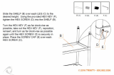
3. Slide the metal backing plate over the bolt ends as they stick out over the rain collec-
tor base. Secure the backing plate with a lock washer and hex nut on each of the bolt
ends as shown previously. Do not tighten the nuts yet.
Note:Leave the nuts loose enough to swivel the ISS base on the pole.
4. The two ends of the anemometer’s U-bolt should now be pointing away from the
mounted rain collector side. Slide the anemometer’s mounting base over the protrud-
ing bolt ends. Place a flat washer, a lock washer and a hex nut on each of the bolt
ends as shown above. Do not tighten the nuts yet.
5. Raise the ISS unit to the desired height on the pole and swivel it so the anemometer
arm is pointing north.
6. Using an adjustable wrench or 7/16" wrench, tighten all four hex nuts until the ISS is
firmly fastened on the pole.
7. Re-attach the rain collector cone by setting the cone back on the base so its latches
slide downward into the latch openings on the base, then rotate the cone clockwise.
8. Place the debris screen (shown in the illustration on page 2) inside the cone, “feet-
down,” over the funnel hole.
Note:When installing the ISS as a single unit, we recommend tucking the coil of anemometer cable
between the rain collector cone and the ISS base.
Installing ISS Only
1. While holding the mounting base against the pole, place the two ends of a U-bolt
around the pole and through the two holes in the base.
2. Slide the metal backing plate over the bolt ends as they stick out toward the rain col-
lector cone. Secure the backing plate with a washer, a lock washer, and a hex nut on
each of the bolt ends. Do not tighten the nuts yet.
For the wireless ISS, swivel the ISS base so the solar panel is facing south (in the
Northern Hemisphere), or north (in the Southern Hemisphere).
3. Using an adjustable wrench or 7/16" wrench, tighten the nuts.
4. Re-attach the rain collector cone.
Set the cone back on the base so its latches slide downward into the latch openings
on the base. Rotate cone clockwise.
5. Place the debris screen (shown in the illustration on page 2) inside the cone, “feet-
down,” over the funnel hole.
Installing Anemometer Only
1. While holding the mounting base against the pole, place a U-bolt around the pole and
through the two holes in the base.
2. Place a flat washer, a lock washer and a hex nut on each of the bolt ends.
Additional Mounting Options: Finishing the Installation
15
3. Swivel the anemometer until the arm is pointing north.
If the anemometer arm is not pointing north, go to “Appendix C: Re-orienting the
Wind Vane” on page 21 after tightening the nuts.
4. Using an adjustable wrench or 7/16" wrench, tighten the nuts.
Finishing the Installation
Level the Solar and UV Sensors
If your station includes a solar or UV sensor, use the bubble level on the sensor as a
guide to verify that the sensor is level.
You can adjust the level by tightening or loosening the screws that hold the sensor onto
the shelf.
Securing the SIM Cover
We recommend using screws
to securely fasten the SIM
cover.
1. Make sure the SIM cover is
completely closed with the
plastic latches engaged.
2. Secure the SIM cover
using the two #6 1/2” (3.5
mm x 12 mm) screws
included in the ISS hard-
ware.
Note:Plastic latches alone may not keep the SIM cover fastened during windy conditions. Use screws
to secure the SIM Cover in place.
Clearing Data Collected During Testing and Installation
Now that your ISS is mounted outside, you may want to clear out all data that was
collected in the Vantage Pro console during testing and mounting.
To clear all the collected data in the console:
1. Select the WIND key on the console so that graph icon appears adjacent to the wind
data on the display.
2. Press the 2ND key, then press and hold the CLEAR key for at least six seconds and
until you see “CLEARING NOW” in the console ticker display.
Additional Mounting Options
Extending Wireless Transmission Range
You can use our optional repeater stations to extend the wireless transmission range:
Wireless Repeater, AC-Powered #7624
Wireless Repeater, Solar-Powered #7625
Extending the Console Cable (Cabled ISS Only)
You can install a Cabled ISS up to 1000’ (300m) away from the console by using our
extension cables, #7876.
Secure cover with two (2)
self-threading screws
#6 x 1/2" (3.5 x 12 mm).
2
SIM Cover SIM Housing
Close cover. Make sure
plastic latches engage.
1
Maintenance: Relocating the Anemometer
16
Relocating the Anemometer
Using Extension Cables:
Note: Not all cables are compatible with your Vantage Pro system. To be sure they will work, order Davis
extension cables from your dealer or directly from Davis Instruments.
If you would like to locate the anemometer more than 40’ (12 m) from the ISS, use our
extension cables #7876.
Be aware that the maximum measurable wind speed reading decreases as the total
length of cable from the anemometer to the ISS increases. If the cable length is greater
than 540' (165m), the maximum measurable wind speed may be less than 100 mph
(161 km/h).
Using the Anemometer Transmitter Kit (Wireless ISS Only)
Use the Anemometer Transmitter Kit #6330 to add an independent wireless transmitter to
your anemometer. The kit allows the anemometer to function as a transmitter station
sending wind data directly to the console, instead of transmitting via the ISS.
Remote Mounting the Solar and UV Sensors
The solar and UV sensors have a 3' (0.9m) cable. If you wish to install these sensors away
from the ISS, you can extend the length of the sensor cables with our extension cables,
#7876.
Note: Not all cables are compatible with your Vantage Pro system. To be sure they will work, order Davis
extension cables from your dealer or directly from Davis Instruments.
Optional Wireless Stations
Use our optional wireless sensor stations to collect additional weather measurements,
without the inconvenience of routing cables:
Wireless Temperature Station #6370
Wireless Temperature/Humidity Station #6380 or #6385
Wireless Leaf & Soil Moisture/Temperature Station #6343
For more details, please visit our website or see the Weather Instruments catalog. Some
information is also available in “Appendix A: Wireless Transmitter IDs” on page 19.
Maintenance
Maintaining UV and Solar Radiation Sensors
Make every effort to avoid touching the small white diffusers at the top of the sensors.
Any skin oil will reduce the sensitivity of the sensors. For accurate readings, clean the dif-
fusers at least once per month using ethyl alcohol on a soft cloth (NOT rubbing alcohol).
Due to the sensitivity of ultraviolet and solar radiation sensors it is common practice for
manufacturers to recommend re-calibration after a period of time. Here at Davis
Instruments we have seen less than 2% drift per year on the readings from these
sensors. For applications demanding higher accuracy, however, the sensors should be
calibrated once every year.
Contact Technical Support about returning your sensor for calibration. See “Contacting
Davis Instruments” on page 18.
Troubleshooting: Cleaning the Radiation Shield
17
Cleaning the Radiation Shield
Check the radiation shield for debris or insect nests
at least once a year and clean when necessary. A
buildup of material inside the shield will reduce its
effectiveness and may cause inaccurate
temperature and humidity readings.
To clean the radiation shield:
1. Remove the rain collector cone.
2. Using a Phillips head screwdriver, loosen the
three 4” (~100mm) bolts holding the radiation
shield plates together.
3. Separate the plates as shown and remove all
debris from inside the shield.
4. Reassemble the radiation shield plates and fas-
ten them together using the bolts as shown in
the illustration. Use a Phillips screwdriver to
tighten the bolts.
Cleaning the Rain Collector
To maintain accuracy, thoroughly clean the rain
collector several times a year.
Note: Cleaning the tipping bucket may cause false rain
readings. See your Vantage Pro Console Manual for
instructions on clearing weather data.
1. Separate the cone from the base by turning it
counter-clockwise.
2. Use soapy water and a soft cloth to remove any debris from the cone, cone screen,
and tipping bucket. Watch out for spiders — they seem to like rain collectors!
3. Use pipe cleaners to clear the funnel hole in the cone and drain screens in the base.
4. When all parts are clean, rinse with clear water.
5. Re-attach the cone and replace the debris screen.
Troubleshooting
If a Sensor Functions Intermittently
Carefully check all connections from the sensor to the ISS. See “Check SIM Sensor
Connections” on page 4.
Loose connections account for a large portion of potential problems. Connections should
be firmly seated in receptacles, and plugged in straight. If you think a connection may be
faulty, try jiggling the cable while looking at the display. If a reading appears intermittently
on the display as you jiggle the cable, the connection is faulty. Try removing and then re-
installing the cable to correct the faulty connection. If the sensor still functions
intermittently contact Davis Technical Support.
The Most Common Rain Collector Problem
If the rain collector seems to be under-reporting rainfall, remove the rain collector cone to
clean the tipping bucket and clear out any debris.
4" Bolt
Plates
ISS Base
TEMP
HUM
Sensor
Lock Washer
Flat Washer
ISS Radiation Shield Assembly
Troubleshooting: The Most Common Anemometer Problems
18
The Most Common Anemometer Problems
Note: If the anemometer is sending no data, the wind display indicates 0 speed and a North direction.
“The anemometer head is tilted when I mount the anemometer.”
With your Allen wrench, loosen the screws holding the anemometer head on the arm.
(The screws are on the bottom of the anemometer head, by the wind cups.) Turn the
anemometer head so it is straight and then tighten the screws.
“The wind cups are spinning but my console displays 0 mph.”
The signal from the wind cups may not be making it back to the display. Remove the cups
from the anemometer (loosen the set screw shown on page 4). Put the cups back onto
the shaft and adjust them up or down 1/16 – 1/8 inch (1.5 – 3 mm). Check your cables for
visible nicks and cuts. Look for corrosion in the “WIND” jack on the SIM and on splices in
the cable (if any). If you are using an extension cable, remove it and test using only the
anemometer cable. If you still haven’t resolved the problem, contact Technical Support
and ask for a wind test cable.
“The wind direction is stuck on north, or displays dashes.”
It is likely that there is a short or break somewhere between the wind vane and the
display. Check your cables for visible nicks and cuts. Look for corrosion in the “WIND”
jack on the Sensor Interface Module and on splices in the cable (if any). If possible,
remove any extensions and try with the anemometer cable only. If none of these steps
get the wind direction working, contact Technical Support and ask for a wind test cable.
“The wind cups don’t spin or don’t spin as fast as they should.”
First check for and clear out any spider webs. Also, the anemometer may be located
where wind is blocked by something, or there may be friction interfering with the cups’
rotation. Friction usually can be remedied by the user — remove the wind cups (loosen
the set screw shown on page 4) and clear out any bugs or debris. Turn the shaft the cups
rotate on. If it feels gritty or stiff, contact Davis Technical Support. DO NOT LUBRICATE
THE SHAFT OR BEARINGS IN ANY WAY. When replacing the cups, make sure they are
not rubbing against any part of the anemometer head.
“Wind readings aren’t what I expected them to be.”
Comparing data from your ISS to measurements from TV, radio, newspapers, or a
neighbor is NOT a valid method of verifying your readings. Wind speed and direction can
vary considerably over short distances. How you site the anemometer can also make a
big difference. If you have questions, contact Technical Support.
Contacting Davis Instruments
If you have questions about your ISS or Vantage Pro Station, or encounter problems
installing or operating your weather station, please contact Davis Technical Support.
Note: Please do not return items to the factory for repair without prior authorization.
(510) 732-7814 – Technical Support phone, Monday – Friday, 7:00 a.m. – 5:30 p.m.
Pacific Time.
(510) 670-0589 – Technical Support Fax.
suppor[email protected] – E-mail to Technical Support.
[email protected] – General e-mail.
www.davisnet.com – Download manuals and specifications from the Support
section. Watch for FAQs and other updates. Subscribe to the e-newsletter.
  • Page 1 1
  • Page 2 2
  • Page 3 3
  • Page 4 4
  • Page 5 5
  • Page 6 6
  • Page 7 7
  • Page 8 8
  • Page 9 9
  • Page 10 10
  • Page 11 11
  • Page 12 12
  • Page 13 13
  • Page 14 14
  • Page 15 15
  • Page 16 16
  • Page 17 17
  • Page 18 18
  • Page 19 19
  • Page 20 20
  • Page 21 21
  • Page 22 22
  • Page 23 23
  • Page 24 24

DAVIS Vantage Pro2 ISS User manual

Category
Dehumidifiers
Type
User manual
This manual is also suitable for

Ask a question and I''ll find the answer in the document

Finding information in a document is now easier with AI