Page is loading ...

Installation and Operation Manual
X-VA-GT1600-eng
Part Number: 541B220AAG
April, 2020
GT1600 Series
Brooks
®
GT1600
Industrial Glass Tube Variable Area Flowmeter
GT1600 Series

ESD (Electrostatic Discharge)
CAUTION: This instrument contains electronic components that are susceptible to damage by static electricity. Proper handling procedures must be observed
during the removal, installation or other handling of internal circuit boards or devices.
Handling Procedure:
1. Power to unit must be removed.
2. Personnel must be grounded, via a wrist strap or other safe, suitable means before any printed circuit card or other internal device is installed,
removed or adjusted.
3. Printed circuit cards must be transported in a conductive container. Boards must not be removed from protective enclosure until immediately before
installation. Removed boards must immediately be placed in protective container for transport, storage or return to factory.
Comments
This instrument is not unique in its content of ESD (electrostatic discharge) sensitive components. Most modern electronic designs contain components
that utilize metal oxide technology (NMOS, SMOS, etc.). Experience has proven that even small amounts of static electricity can damage or destroy these
devices. Damaged components, even though they appear to function properly, exhibit early failure.
Brooks Instrument designs, manufactures and tests its products to meet many national and international standards. These products must be properly
installed, operated and maintained to ensure they continue to operate within their normal specifications. The following instructions must be adhered to
and integrated into your safety program when installing, operating and maintaining Brooks Instrument products.
•To ensure proper performance, use qualified personnel to install, operate, update, program and maintain the product.
•Read all instructions prior to installing, operating and servicing the product. If this instruction manual is not the correct manual, please see back cover
for local sales office contact information. Save this instruction manual for future reference.
WARNING: Do not operate this instrument in excess of the specifications listed in the Instruction and Operation Manual. Failure to heed
this warning can result in serious personal injury and / or damage to the equipment.
• If you do not understand any of the instructions, contact your Brooks Instrument representative for clarification.
• Follow all warnings, cautions and instructions marked on and supplied with the product.
WARNING: Prior to installation ensure this instrument has the required approval ratings to meet local and national codes. Failure to heed this warning can
result in serious personal injury and / or damage to the equipment.
• Install your equipment as specified in the installation instructions of the appropriate instruction manual and per applicable local and national codes.
Connect all products to the proper electrical and pressure sources.
• Operation: (1) Slowly initiate flow into the system. Open process valves slowly to avoid flow surges. (2) Check for leaks around the flow meter inlet
and outlet connections. If no leaks are present, bring the system up to the operating pressure.
• Please make sure that the process line pressure is removed prior to service. When replacement parts are required, ensure that qualified people use
replacement parts specified by Brooks Instrument. Unauthorized parts and procedures can affect the product's performance and place the safe
operation of your process at risk. Look-alike substitutions may result in fire, electrical hazards or improper operation.
• Ensure that all equipment doors are closed and protective covers are in place to prevent electrical shock and personal injury, except when
maintenance is being performed by qualified persons.
WARNING: For liquid flow devices, if the inlet and outlet valves adjacent to the devices are to be closed for any reason, the devices must be completely
drained. Failure to do so may result in thermal expansion of the liquid that can rupture the device and may cause personal injury.
All pressure equipment with an internal pressure greater than 0.5 bar (g) and a size larger than 25mm or 1" (inch) falls under the Pressure Equipment Directive (PED).
• The Specifications Section of this manual contains instructions related to the PED directive.
• Products described in this manual are in compliance with EN directive 2014/34/EU.
• All Brooks Instrument Flowmeters fall under fluid group 1.
• Products larger than 25mm or 1" (inch) are in compliance with PED category I, II or III.
• Products of 25mm or 1" (inch) or smaller are Sound Engineering Practice (SEP).
The Brooks Instrument (electric/electronic) equipment bearing the CE mark has been successfully tested to the regulations of the Electro Magnetic
Compatibility (EMC directive 2014/30/EU).
Special attention however is required when selecting the signal cable to be used with CE marked equipment.
Quality of the signal cable, cable glands and connectors:
Brooks Instrument supplies high quality cable(s) which meets the specifications for CE certification.
If you provide your own signal cable you should use a cable which is overall completely screened with a 100% shield.
“D” or “Circular” type connectors used should be shielded with a metal shield. If applicable, metal cable glands must be used providing cable screen clamping.
The cable screen should be connected to the metal shell or gland and shielded at both ends over 360 Degrees.
The shield should be terminated to an earth ground.
Card Edge Connectors are standard non-metallic. The cables used must be screened with 100% shield to comply with CE certification.
The shield should be terminated to an earth ground.
For pin configuration : Please refer to the enclosed Instruction Manual.
European Pressure Equipment Directive (PED)
European Electromagnetic Compatibility (EMC)
Essential Instructions
Read before proceeding!

WARNING
WARNING
GLASS TUBE EXPLOSION HAZARD
GLASS TUBE
EXPLOSION
HAZARD
Plastic protective sleeve must remain over glass
tube. (Meter sizes 7-10 only)
Fasten meter window securely.
Do not operate above pressure and temperature
limits.
Avoid pressure and ow surges.
Do not service or repair while pressurized.
Read and understand instruction manual.
Failure to comply could result in serious personal
injury or property damage.
Protective sleeve must remain over glass tube.
(Meter sizes 7-10 only)
Fasten meter windows securely.
Failure to comply could result in serious personal
injury or property damage.
Brooks Instrument Serial Number Format(s)
Format 1 - All devices will transition to this format
EXAMPLE: 01B20080023
EXAMPLE: 01 B 2 0 08 0023
01 - Organization
B - Decade (A: 2000 - 2009, B: 2010-2019, ect.)
2 - Year within decade (B2 = 2012)
08 - Week of Year
0 - Warranty Period
0023 - Weekly counter

Contents
Section 1 Introduction
Design Features ............................................................................................................................................... 1
Principle of Operation ....................................................................................................................................... 1
Specications ................................................................................................................................................... 2
Optional Equipment - Alarms & Valves ............................................................................................................ 10
Section 2 Installation
General ........................................................................................................................................................... 17
Receipt of Equipment ...................................................................................................................................... 17
Recommended Storage Practice .................................................................................................................... 17
Return Shipment ............................................................................................................................................. 17
Transit Precautions ......................................................................................................................................... 18
Installation ....................................................................................................................................................... 18
Section 3 Operation
Pre-Operational Check .................................................................................................................................... 19
Operating Instructions ..................................................................................................................................... 19
Section 4 Maintenance
Overview ......................................................................................................................................................... 21
Cleaning .......................................................................................................................................................... 22
Section 5 Parts Assembly
General ........................................................................................................................................................... 23
Warranty, Local Sales/Service Contact Information ........................................................................Back Cover

Contents
Figures
Figure
Number
1-1 Principle of Operation ............................................................................................................................. 1
1-2 Cross-Section - GT1600 Flow Tubes with Rib Guides ........................................................................... 1
1-3 GT1600Floats(Descriptionsrefertooatsusedinthesamesizetube)) .............................................. 2
1-4 Dimensions - GT1600 Series ................................................................................................................. 5
1-5 Reed Switch Alarm UL Installation ........................................................................................................ 13
1-6 BistableInductiveSwitchesforGT1600Sizes2-6 .............................................................................. 15
1-7 DimensionsandSpecications,IntrinsicallySafeSwitchIsolators ....................................................... 16
2-1 TypicalFlowmeterPipingConguration ................................................................................................ 18
3-1 TypicalFlowmeterPipingConguration ................................................................................................20s
5-1 GT1600,Sizes2and6PartsAssemblyDrawing .................................................................................. 23
5-2 GT1600,Sizes7-10PartsAssemblyDrawing ....................................................................................... 24
Tables
Table
Number
1-1 Specications-GT1600 ......................................................................................................................... 3
1-2 Capacities - GT1600 ............................................................................................................................... 4
1-3 Dimensions - GT1600 ............................................................................................................................. 7
1-4 Approvals ................................................................................................................................................ 8
1-5 GT1600Size2to10Non-Electrical ....................................................................................................... 9
5-1 PartsAssemblyItemIdentication ......................................................................................................... 25

Section 1
Figure 1-1 Principle of Operation
Design Features
• Configurabletoretro-fitGT10xx,GT130xandFull-View
• 360 degrees rotatable viewing angle
• Highqualitymaterialsforsafety,in-andoutdoordurability
• 316 stainless steel frame
• Polycarbonatesafetyshield
• 316/316Ldualcertifiedstainlesssteelprocessfittings
• Alarmsforhigh-andlowflow(optionalforallflowranges,eitherattimeof
order, or as add-oninthefield)
• Flangedorthreadedconnections,availablehorizontalandvertical
• Panel- and wall mount options
• Easyin-situmaintenance:Cleanorreplacetubeandfloatwithoutremoval
from the process piping
• Adjust the scale to compensate for process variation
• Optional integral needle valve
Principle of Operation
Theoperatingpartsoftheowmeterconsistofataperedglasstubeanda
oatwhichoperateswithinthetube.Theuidentersthebottomofthetube,
whichhasthesmallestinsidediameter(andsmallestarea),andexitsfrom
thetop,whichhasthelargestinsidediameter(andlargestarea).Theoatis
free to operate between the largest and smallest areas of the tube.
Refer to Figure 1-1.
Astheoatmovesupanddownwithinthetaperedtube,theannulararea
betweentheoatandtubevaries(areaincreasesastheoatrises).This
gives the generic name of "variable area meter" for this measurement
principle.Astheowvaries,theoatwillmovewithinthetubeuntilitreaches
an equilibrium position, where the tube taper creates an appropriate annular
areatobalancetheforcesofgravityandtheuidsactingontheoat.
Refer to Figure 1-2.
Figure 1-2 Cross-Section - GT1600 Flow Tubes with Rib Guides
1 2

Section 1
Figure 1-3 GT1600 Floats (Descriptions refer to oats used in the same size tube)
TherearefourtypesofoatsavailablefortheGT1600owmeter.
Refer to Figure 1-3.
Guideribsareformedintothetubetokeeptheoatoperatinginthecenterof
thetube.Theguideribsdonotfollowthetaperofthetube.Theyareparallel
tothetubecenterlinesothattheproperoperatingclearancefortheoatis
maintained for its entire range of travel. The increasing annular area of the
tube is in the area between the ribs.
Refer to Figure 1-2.
Specications
1 2
If flow is crical, evaluate the funconal safety
to help prevent systemac failures from being introduced.

Section 1
Table 1-1 Specications - GT1600
CapacitiesandPressureDrops
FlowAccuracy
Repeatability
Scales
AmbientTemperatureLimits
OperatingFluidTemperatureLimits
Mountingoptions
PanelͲmount(seeDimensions)
Standard:±10%,±5%,±2%FullScale,Class2.5accVDI/VDE
Optional:±1%FullScale,Class1.6accVDI/VDE
ч0.5%FullScale
SeeCapacities
Transparantscale.Adjustable
NominalLengths:75mm,127mmand250mm
Choiceofdirectreadingunits,millimeterorpercentageofmaximumflowwithfactortag.
Ͳ4°Fto125°F|Ͳ20°Cto52°C
33to250°F|1°Cto121°C
InͲline
WallͲmount(seeDimensions)
psi bar psi bar
02 500 34.5 240 16.5
06 450 31.0 240 16.5
07 300 20.7 240 16.5
08 250 17.0 240 16.5
09 200 13.8 200 13.8
10 175 12.1 175 12.1
Metering Tube (weed)
Process fings (weed)
Float Stops (weed)
O
rings (weed)
Housing
Window & safety shield
Hardware
Tube size 02&06
Tube size 07
10
Pressure Rangs
Float (weed)
Materials of
construcon
Maximum Operang Pressure (PSIG | bar) at
Max Operang
Temperature
Tube size Threaded process connecons Flanged process connecons
Horizontal IN/OUT Horizontal IN/OUT
Vercal IN/ Horizontal OUT
Process connecons NPT Threaded Flanged ANSI 150# RF
Vercal IN/ Horizontal OUT
Vercal IN/OUT
Polycarbonate with UV inhibitor
316 stainless steel
Valve Oponal integral needle valve
Div1/Div2 (CSA) – gas/dust. Protecon method I.S. / Non
incendive
Zone1/Zone2 (CSA/ATEX/IECex) – gas/dust. Protecon method Ex
m (no barrier)
Alarms Ring iniator high / low alarm
Hazardous area approvals
Material Cerficaon to DIN 3.1
Declaraon of Compliance 2.1 Oxygen Service
Reed switch high / low alarm
Vercal IN/OUT
Horizontal IN/ Vercal OUT Horizontal IN/ Vercal OUT
316/316L (dual cerfied stainless steel)
Viton®, Buna
N, Kalrez®, EPDM
Sizes 2&6: Carboloy® or 316/316L (dual cerfied stainless steel)
Sizes 7
10: 316/316L (dual cerfied stainless steel)
Teflon®
Borosilicate glass
Cerficaons Internaonal Calibraon Cerficate
316 stainless steel
3 4

Section 1
Table 1-2 Capacities - GT1600
cc/min l/h ln/h
SLPM
R
2 127 AAAA
T
316SS 1.9 0.11 0.11 6.7
R
2 127 AAAA
T
CARBOLO
Y
3.7 0.22 0.2 12
R
2 127 AA
T
CARBOLO
Y
7.5 0.45 0.38 23
R
2 127 D
T
316SS 15 0.93 0.68 40
R
2 127 D
T
CARBOLO
Y
25 1.5 161
R
2 127 A
T
316SS 39 2.3 1.4 86
R
2 127 A
T
CARBOLO
Y
59 3.5 2 120
R
2 127 B
T
316SS 110 6.8 3.9 230
R
2 127 B
T
CARBOLO
Y
170 10 5.6 340
R
2 127 C
T
CARBOLO
Y
270 16 9 540
R
6 127 A
T
316SS 410 25 14 850
R
6 127 A
T
CARBOLO
Y
620 37 20 1200
R
6 127 B
T
316SS 1000 65 35 2100
R
6 127 B
T
CARBOLO
Y
1500 95 49 2900
GPM l/h
SCFM
m3n/h
7
XV 11A
A
0.48 100 1.8 3.1
7
XS 23
A
0.77 170 3.3 5.6
8
XV 8
A
1.00 240 4.4 7.5
8
XV 14
A
1.40 320 5.8 9.9
2.00 460 14 24
9
XS 33
A
3.20 730 13 22
3.90 890 28 48
5.10 1100 36 62
10
XV 64
A
6.20 1400 25 43
10
XS 64
A
7.80 1700 32 54
10.00 2400 80 130
21.00 4800 150 270
7-XV-11A-A 0.41 93 1.8 3.1
7-XS-23-A 0.66 150 2.7 4.6
8-XV-8-A 0.99 220 46.9
8-XV-14-A 1.3 310 5.3 9.1
8-XV-31-A* 1.7 400 11 20
9-XS-33-A 3.0 690 12 21
9-XV-87-A* 3.6 830 26 44
9-XS-87-A* 4.5 1000 32 55
10-XV64-A
6 1300 24 41
10-XS-64-A 7.4 1600 30 52
10-XS-138-A* 9.8 2200 68 110
10-XJ-238-A*
20 4700 140 250
8
XV 8 A
0.82
180
3.3
5.6
8
RJ 10
1.5
340
6.3
10
8
RJ 23
2.4
540
9.9
16
8
RJ 30
3.1
710
13
22
8
RJ 39
4.7
1000
10
RJ 8
0
12 2700
10
RJ 18
0
21 4900
10
RJ 37
24
40
10
RJ 83
36
62
10
RJ 90
55
93
Note (1) Airflow rates in standard units are at 70°F & 14.7 psia
Note
* These codes require a back pressure of 30 psig / 2bar
(2) Airflow rates in normal units are at 1.013 bar & 20°C
Meter type
127
Low Flow
Size 08 R
8M 75 1
Size 10 R
10M 75 3
075
High Flow
Ring iniator
Tube Alarm typeFloat
Size 02
Size 06
Full scale
water Full scale air
250
High Flow Size 07
Reed switch
Size 10
Size 09
Size 08
R
7M 25 1FT
R
8M 25 4FT
R
9M 25 3FT
R
10M 25 3FT
127
High Flow R 7M 127 1F
R
8M 127 4F
R
9M 127 3F
R
10M 127 3FSize 10
Size 07
Size 08
Size 09
8-XV-31-A*
9-XV-87-A*
9-XS-87-A*
10-XS-138-A*
10-XJ-238-A*
3 4

Section 1
Figure 1-4 Dimensions - GT1600 Series (See Dimensions Tables on following pages)
5
6

Section 1
Table 1-3 Dimensions - GT1600
(Dimensions Table continued on following page)
inch mm inch mm inch mm inch mm inch mm inch mm
H-IN / H-OUT 1020 8.59 218.3 0.59 15.0
V-IN / V-OUT 1024 9.84 250.0 - -
H-IN / V-OUT 1026 9.22 234.1 0.59 15.0
V-IN/ H-OUT 1027 9.22 234.1 0.59 15.0
H-IN / H-OUT 1110 8.59 218.3 0.59 15.0
V-IN / V-OUT 1114 9.63 244.5 - -
H-IN / V-OU 1T 140 9.11 231.4 0.59 15.0
V-IN/ H-OUT 1144 9.11 231.4 0.59 15.0
H-IN / H-OUT 1020 8.59 218.3 3.50 75.0
V-IN / V-OUT 1024 10.63 270.0 - -
H-IN / V-OU 1T 026 9.61 244.1 2.95 75.0
V-IN/ H-OUT 1027 9.61 244.1 2.95 75.0
H-IN / H-OUT 1140 8.59 218.3
V-IN / V-OUT 1144 377.8 - -
H-IN / V-OU 1T 146 11.73
V-IN/ H-OUT 1147 11.73
H-IN / H-OU 1T 020 17.50 444.5 0.91 23.0
V-IN / V-OUT 1024 19.69 500.0 - -
H-IN / V-OU 1T 026 18.59 472.3 0.91 23.0
V-IN/ H-OUT 1027 18.59 472.3 0.91 23.0
H-IN / H-OUT #7/8 16.50 419.1
H-IN / H-OUT
#9/10 17.50 444.5
V-IN / V-OUT #7/ 18 7.00 431.8
V-IN / V-OUT #9/10 17.25 438.2
H-IN / V-OUT #7/ 18 6.75
425.5
H-IN / V-OUT #9/1 10 7.38 441.3
V-IN/ H-OUT #7/ 18 6.75 425.5
V-IN/ H-OUT #9/10 17.38 441.3
V-IN / V-OUT
Retrofit only
(4)
GT1307 1307
16.94 430.2 - -
H-IN / H-OUT #7/8 3.94 100.0
H-IN / H-OUT #9/1 40 .72 120.0
V-IN / V-OUT
1024
19.69 500.0 - -
H-IN / V-OUT #7/8 3.94 100.0
H-IN / V-OUT #9/1 40 .72 120.0
V-IN/ H-OUT #7/ 38 .94 100.0
V-IN/ H-OUT #9/10 4.72 120.0
H-IN / H-OUT #7/
22.88
8 3 .50 88.9
H-IN / H-OUT #9/10 4.00 101.6
V-IN / V-OUT #7/
1
8
7.00 419.1
V-IN / V-OUT #9/10
17.25 444.5
H-IN / V-OUT #7/8 3 .50 88.9
H-IN / V-OUT #9/10 4 .00 101.6
V-IN/ H-OUT #7/8 3 .50 88.9
V-IN/ H-OUT #9/10 4 .00 101.6
Note (3) - Standard dimension
Note (4) - Retro-fit dimensions are for replacement of GT10xx, GT130x and Full-View meters in e in new in .
6.0
Full-View
Retrofit only
(4)
Flanged
150lbs RF
Notes
Dimension
A B C L M N
Meter type
Tube
size
Process
on
Or
n
H(orizontal)
V(er
al R) etro-fit Model
50.0 4.00 101.
6 1.00 25.4
127-Low Flow 02
06
NPT- GF T1000Standard
dimensions
(3)
1.97 0.24
1110 0.91 23.0
1114 - -
1116
70.0 8.002.76
0.91 23.0
1117 0.91
18.59 472.3
GT1000Standard
dimensions
(3)
Full-View
Retrofit only
(4)
1027
250-High Flow 07
08
09
10
Standard
dimensions
(3)
Full-View
Retrofit only
(4)
Full-View
1140
Retrofit only
(4)
1144
GT1000Flanged
150lbs RF
1020
1026
NPT- GF T1000Standard
dimensions
(3)
1146
1147
- -
7.0203.2 1.63 41.28 0.28
23.0
17.50 444.5
18.59 472.3
P Q
3.00
101.6
14.88
298.1
298.1
3.00 101.6
3.00 101.6
1847.24
37.61.48
393.515.49
69.72.74
581.0
22.50 571.5
19.69 500.0
20.00 508.0
19.69 500.0
20.00 508.0
inch mm
inch mm
5 6

Secion 1
Table 1-3 Dimensions - GT1600 (continued)
inch mm inch mm inch mm inch mm inch mm inch mm
H
IN / H
OUT
12.31 312.7 0.91 23.0
V
IN / V
OUT
14.50 368.2
H
IN / V
OUT
13.41 340.5 0.91 23.0
V
IN/ H
OUT
13.95 354.4 0.91 23.0
H
IN / H
OUT #7/8
11.50 292.1
H
IN / H
OUT #9/10
12.50 317.5
V
IN / V
OUT #7/8
12.00 304.8
V
IN / V
OUT #9/10
12.25 311.2
H
IN / V
OUT #7/8
11.75 298.5
H
IN / V
OUT #9/10
12.38 314.3
V
IN/ H
OUT #7/8
11.75 298.5
V
IN/ H
OUT #9/10
12.38 314.3
V
IN / V
OUT
Retrofit only
(4)
GT1306 1306
11.75 298.5
H
IN / H
OUT #7/8
3.94 100.0
H
IN / H
OUT #9/10
4.72 120.0
V
IN / V
OUT #7/8
V
IN / V
OUT #9/10
H
IN / V
OUT #7/8
3.94 100.0
H
IN / V
OUT #9/10
4.72 120.0
V
IN/ H
OUT #7/8
3.94 100.0
V
IN/ H
OUT #9/10
4.72 120.0
H
IN / H
OUT #7/
8
11.50 292.1 3.50 88.9
H
IN / H
OUT #9/1
0
12.50 317.5 4.00 101.6
V
IN / V
OUT #7/8
17.88 454.0
V
IN / V
OUT #9/1
0
17.50 444.5
H
IN / V
OUT #7/8
14.69 373.0 3.50 88.9
H
IN / V
OUT #9/1
0
15.00 381.0 4.00 101.6
V
IN/ H
OUT #7/8
14.69 373.0 3.50 88.9
V
IN/ H
OUT #9/1
0
15.00 381.0 4.00 101.6
H
IN / H
OUT
9.02 229.1 0.83 21.0
V
IN / V
OUT
11.20 284.6
H
IN / V
OUT
10.11 256.9 0.83 21.0
V
IN/ H
OUT
10.11 256.9 0.83 21.0
V
IN / V
OUT
Retrofit only
(4)
GT1305 1305
7.75 196.9
H
IN / H
OUT #7/8
3.94 100.0
H
IN / H
OUT #9/10
4.72 120.0
V
IN / V
OUT #7/8
V
IN / V
OUT #9/10
H
IN / V
OUT #7/8
3.94 100.0
H
IN / V
OUT #9/10
4.72 120.0
V
IN/ H
OUT #7/8
3.94 100.0
V
IN/ H
OUT #9/10
4.72 120.0
Note (3)
Standard dimension are for new installaons
Note
(4)
Retro
fit dimensions are for replacement of GT10xx, GT130x and Full
View meters in exisng installaon. Not for use in new installaons.
Model
Dimension
A B C L M N
1110 0.91 23.0
1114
NPT
F Standard
dimensions
(3)
1116 0.91 23.0
1117 0.91 23.0
Retrofit only
(4)
70.0 N/A2.76
10.11 256.9
10.11 256.9
13.41 340.5
13.41 340.5
1140
1144
Standard
dimensions
(3)
12.31 312.7
14.50 368.2
9.02 229.1
11.20 284.6
Retrofit only
(4)
1146
1147
NPT
F Standard
dimensions
(3)
127
High Flow
075
High Flow 08
10
07
08
09
10
Flanged
150lbs RF
Full
View
GT1000
Full
View
Notes
Flanged
150lbs RF
Standard
dimensions
(3)
Meter type
Tube
size
Process
connecon
Orientaon
H(orizontal)
V(ercal) Retro
fit
7

Section 1
8 9
Product Approvals Overview
Mechanical
Reed Switch
Inductive Alarm
Declaration
Declaration
Declaration
Declaration
CRN
ATEX
IECEX
Explosion safety
"Intrinsic Safety (ia)
"
UL File E73889 Vol3 Sec
6
Explosion safety
"Intrinsic Safety
(ia)"
ATEX
Pepperl + Fuchs
PTB 99 ATEX 2128 X
Pepperl + Fuchs
Control Draw ing:116-
0165G
TCF: 203104000-1604
Explosion safety
"Intrinsic Safety
(ia)"
Inductive Ring Sensor
Non-Hazardous Locations
Pow er Supply
Current consumption
Ambient Temperature
Hazardous Location
ATEX
FM Approvals
Pepperl + Fuchs Model: RC10-14-N3-Y53478
Pepperl + Fuchs Model: RC15-14-N3-Y53479
Nominal Voltage 8V Operating Voltage
5...25V
Active area clear : 3mA (at 8V)
Active area obscured: 0.5...0.95mA (at 8V)
0°C to 40°C
II 2 G Ex ia IIC T6…T1 Gb IP67
Refer to ATEX Certificate for: Input parameters,
Max Ambient Temperature, Special conditions for
use
Class I, Division 1, Group A, B, C, Class II, Division
Standards used for evaluation:
Ambient Temperature range:
Input Pow er:
Special conditions for safe
use:
EN 60079-0 : 2012+A11: 2013, EN 60079-18 : 2015
IEC 60079-0 : 2011, IEC 60079-18 : 2014
-20 °C to +65 °C (Standard Version)
-20 °C to +55 °C (With Junction box Version)
30V, 250mA, 3W
Refer to IOM
Ambient Temperature ratings:
Input parameters:
Special conditions for safe
use:
use:
-20° C ≤ Tamb ≤ 65° C
Vmax = 30V, Imax = 100mA, Ci = 0μF, Li = 0μH
Refer to IOM
IS Class I, II, III, Div 1, Groups A, thru G
Ex mb IIC T6 Gb Ex mb IIIC T85°C Db (Standard Version)
KIWA 18ATEX0013 X
IECEx KIWA 18.0008X
Declarations Mark
Meter Options
Standards/Directives/Marking Status/Certificate
Explosion safety
"Constructional
safety (c)"
ATEX
II2G Ex h IIC T6…T4 Gb
II2D Ex h IIIC T120°C Db
Special conditions for safe use:
Refer to IOM
EU Declaration of
Conformity
EMC Directive (2014/30/EU)
RoHS Directive (2011/65/EU)
EMC Directive (2014/30/EU)
Reed Sw itch Alarms are classified as “Simple Apparatus” w hen used in Intrinsically Safe circuits. They
comply w ith the requirements of EN60079-11 clause 5.7 – Simple apparatus.
Pressure Equipment Directive (2014/68/EU)
EMC Directive (2014/30/EU)
The equipment uses a reed sw itch sensor & is outside the scope of the directive since the inherent nature of
the physical characteristics of w hich is such that:
(i) it is incapable of generating or contributing to electromagnetic emissions w hich exceed a level allow ing
radio and telecommunication equipment and other equipment to operate as intended; and
(ii) it operates w ithout unacceptable degradat
ion in the presence of the electromagnetic disturbance normally
consequent upon its intended use.
Canadian Registration Number (CRN)
Explosion safety
"encapsulation (m)"
II 2 G Ex mb IIC T6 Gb II 2 D Ex mb IIIC T85°C Db (Standard Version)
Ex mb IIC T5 Gb Ex mb IIIC T100°C Db (With Junction box Version)
II 2 G Ex mb IIC T5 Gb II 2 D Ex mb IIIC T100°C Db (With Junction box Version)
Group E, F, G, Class III, Division 1
Class I, Zone 0, Group IIC T6
Table 1-4 Approvals

Section 1
8 9
GT1600 Meter Size 2 to 10
Applicaon Non-El ectrical Equi pment for us e i n Ha za rdous l ocaon
Area Classificaon II 2 G / II 2 D
Protecon Technique Cons trucona l s a fety (c)
Technical Construcon File
203104000-1604 (Archi ved a t DEKRA Cerfica on B.V.)
Ambient Temperature -20°C ≤ Ta ≤ 70°C
Marking
II2G Ex h IIC T6…T4 Gb
II2D Ex h IIIC T120°C Db
Installaon Notes:
Special condions for safe use:
Resistance to Impact:
7 Joules
2 Joules
Degree of mechani ca l risk low
External Cleaning
The product s hould be i ns talled by suitabl y trained personnel, i n a ccordance wi th the a pplicabl e code of
prac ce/ i nstallaon s ta ndards for haza rdous a reas .
The flowmeters s ha l l be perma nentl y grounded by means of the process connecons i n order to a l low
discha rge of el
ectrostac charges via the connecon to ground.
The actual ma ximum s urfa ce temperature of the equi pment depends not on the equi pment i ts elf,
but on
operang condions of the process fl ui d/ga s flowing through the equi pment. The equi pment by itsel f does
not generate heat. Due to this rea s on the temperature class i s ma rked a s a range. The ma ximum permi ed
ambient a nd proces s temperature l i mi ts can be found in the operang i ns trucons .
Supply groundi ng connecon by the proces s connecons or earthing termi nal.
Enclosure contains polycarbona te pa rts. If i t is mounted in a n a rea where the us e of category 2G or 2D
appa ratus i s requi red,
i t mus t be i nstalled s uch tha t ignion s ource due to propagang brush di s charge
sparks a re excluded.
The viewi ng wi ndow is made of polycarbona te. Protecon from i mpa ct s houl d be considered for the viewi ng
Vi ewing window of the meter is ma de of non-conducve component. Care s hould be ta ken to ensure tha t
combus bl e electros ta c chargi ng wi ll not build up during cleani ng/maintena nce of meter. Do not rub.
Metal Enclos ure pa rts
Light-transming pa rt (polycarbonate wi ndow)
•
•
•
•
•
•
•
Table 1-5 GT1600 Size 2 to 10 Non-Electrical

Section 1
Optional Equipment - Alarms & Valves
GT1600 Alarm Contacts Meter Sizes 7 to 10
TheBrooksreedswitchalarmisanormallyopen,latchingswitchusedin
conjunctionwiththeGT1600glasstubeowmeterforsignalinghighand/or
lowoworadeviationfromaowsetting.
Amagnetembeddedandsealedintheoatactuatesthealarmswitch.The
reedswitchismountedadjacenttotheowtubeandiseasilyadjustableover
theentireowrangeoftheinstrument.
Thesealedreedswitchconsistsofabiasingmagnetandhermeticallysealed
reed switch, which is insulated to prevent damage from mild shock and
normalpipevibration.Thecontactratingoftheswitchisverylow(0.5A).
Anexternalrelayisrecommendedforsecureoperation.Plustheexternal
relaycanbeconguredtooperateasanormallyopenornormallyclosed
statewhichprovidestotallyexibiltyofoperation.
Alarm Specications:
Operating Fluid Temperature Limits
Reed Switch: Same as meter
Inductive:185°F(85°C)max.
Reed Switch Limits - Non-hazardous Locations
MaximumVoltage*:175Vdc,124Vac
MaximumCurrent*:250mA
MaximumContactRating:3Watts
*(MaximumSwitchSpecications)
Alarm Hysteresis
8mmtypical(0.32in)
10 11

Section 1
GT1600 Alarm Contact (Reed Switch) Meter Size 7 to 10
Applicaon El ectrica l Equi pment for us e i n Ha zardous l oca on
Area Classificaon II 2 G/ II 2 D
Protecon Technique encaps ul aon (m)
Cerficate IECEx KIWA 18.0008X a nd KIWA 18ATEX0013 X
Electrical Data: Swi tchi ng Vol ta ge: max. 30 V
Swi tchi ng Current: max. 250 mA
Swi tchi ng Power: ma x. 3 W
Meter Opons Standard Version Juncon Box Version
Details 1000 mm cable connecon Wi th juncon box and termi na l connecons
Ambient Temperature: -20°C … +65°C -20°C … +55°C
Marking Ex mb IIC T6 Gb Ex mb IIC T5 Gb
Ex mb IIIC T85°C Db Ex mb IIIC T100°C Db
Installaon Notes:
•
•
•
Special condions for safe use:
•
•
•
•
Standard Version Juncon box Version
1 = Cus tomer conne con
2 = Poten al free
(2 wi res for ea ch reed swi tch)
3 = Connecon to customer device
The current through the Reed Switch mus t be l imited to i ts ma x swi tchi ng current us ing a s ui tabl y rated fuse
of ma x 0.5Amps. The fuse mus t have a brea ki ng ca pa city i n a ccorda nce with the pros pecve s hort-ci rcui t
current of the circuit to properly break the s ystems highes t s hort ci rcui t current.
In ca se device i s mounted in an a rea where the use of EPL Gb/Db (Category 2G/D) or EPL Gc/Dc (Category 3G/D)
apparatus i s requi red,
the trans pa rent cover mus t be ins tall ed s uch, that i gni on s ources due to el ectros ta c
di s cha rge spa rks a re excluded.
Standard Vers ion:
Al l entry devices s ha ll onl y be i ns ta ll ed s uch that there i s a l ow risk from mechani cal i mpact.
The cabl e of the reed s wi tch s ha l l be protected aga ins t dama ge.
Junc on box Vers ion:
If the M20X1.5- M to ½” NPT –F Adaptor is us ed i t s hal l be protected from mechani cal impact.
An a ddi onal externa l connec on fa cili ty for a n equipotena l bonding conductor is provided on the meta lli c
enclos ure.
Si nce the reed conta ct i s poten al -free, the termina ls/wi res a re not l abel ed.
Sta ndard Vers ion:
The connec ng cabl es of the reed s wi tch a la rm either ha ve to be outs i de the expl osive
area or if within shall have to be connected with an appropriate connecon housing which complies with the Ex-protecon-class.
10
11

Section 1
GT1600 Alarm Contact (Reed Switch) Meter Size 7 to 10
Applicaon El ectrica l Equipment for use i n Ha zardous locaon
Area Classificaon II 2 G
Protecon Technique Intrins ic s afety (The el ectrical equipment operates a s a s i mple device)
Cerficate None (Reference 60079-11, pa ra. 5.7)
Electrical Data: Vma x = 30V, Ima x = 100mA, Ci = 0μF, Li = 0μH
Ambient Temperature: -20°C … +65°C
Electrical Connecon: 1: Standard Version - 1000 mm ca bl e connecon, one or two wi res
2: Junc on Box Version - Wi th juncon box and termi na l connecons
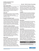
Installaon Notes:
•
•
•
Special condions for safe use:
•
•
•
The i ntrins i cal ly s afe equipment ma y only be connected to s eparated i ntrinsica lly safe circuits .
An a ddi onal external connec on facil ity for an equipotenal bondi ng conductor is provided on the meta l li c
enclos ure.
The product s hould be ins ta ll ed by s uitably trained personnel, i n a ccordance wi th the a ppl icable code of
pracce.
As the product has no s ource of i nterna l hea ng, the temperature clas s ifica on i s dependent on the a mbient
air temperature.
Since part of flowmeter enclosure is made of plasc materials, if it is mounted in group II, category 1 area, it must be installed such,
that, ignion sources due to electrostac discharge sparks are excluded.
- (ATEX)
12 13
GT1600 Alarm Contact (Reed Switch) Meter Size 7 to 10
Applicaon Electrical Equipment for us e i n Haza rdous locaon
Area Classificaon Clas s I, II, III, Div 1, Groups A, thru G
Protecon Technique Intri ns ic s afety
Cerficate UL Recogoni zed
- C North America

Section 1
12
13
Figure 1-5 Reed Switch Alarm UL Installation

Section 1
Inductive Alarms,
Alarm Contacts Meter Sizes 2 and 6
Inductivecoilsforhighand/orlowowalarmmaybemountedtothe
instrumenttocreateahighlysensitive,stableandaccuratedevicefor
signalinghighorlowowsordeviationsfromacontrolledow.Theinductive
alarmcanonlybeusedincombinationwith316SSorCarboloy
®
balloats.
Thealarmpointsmaybeadjustedovertheentireowmeterrangeandbe
setsothatanytwocontactsmaybemadetooperatesimultaneously.For
hazardousareaapplicationsBrookscansupplyanapprovedNamurpower
supplyamplier/relayunittoobtainanintrinsicsafecurrentcircuit.
(PleaserefertoTable1-4).
Table 1-9 Data 10 & 15-14-N3 Inductive Coils
Operating Fluid Temperature Limits
Reed Switch: Same as meter
Inductive:167°F(75°C)max.
Alarm Hysteresis
8mmtypical(0.32in).
Alarm Accessories
Remotely mounted, switch isolator/power supplies are required for inductive
alarms and recommended for reed switch alarms. One or two single-pole,
double-throw (SPDT) relays are available with either 110 or 220 AC volt units.
Optional Needle Valves
For ow rate control, needle valves may be integral to the inlet or outlet side
of the instrument. Note, solenoid valves should not be used because this
type of valve can cause pressure shocks which can damage the glass tube.
Power Supply
Current Consumption
Current Consumption
Self Inductance
Self Capacitance
Max. Temperature
Enclosure Type:4
EMC Directive
8 volt normal (max. 15>5 Vdc)
Active area clear: > 3 mA
Active area obscured: < 1 mA
70 µH
90 nF
75°C
IP67
EN 60947-5-2 DIN EN 60947-5-6 (Namur)
14 15

Section 1
Alarm Accessories
Remotelymounted,switchisolator/powersuppliesarerequiredforinductive
alarms and recommended for reed switch alarms. One or two single-pole,
double-throw(SPDT)relaysareavailablewitheither110or220ACvoltunits.
Optional Needle Valves
Forowratecontrol,needlevalvesmaybeintegraltotheinletoroutletside
of the instrument. Note, solenoid valves should not be used because this
typeofvalvecancausepressureshockswhichcandamagetheglasstube.
GT1600 Alarm Contact (Bistabble Inducve Switches) Meter Size 2 to 6
Applicaon El ectrica l Equi pment for us e i n Ha za rdous loca on
Area Classificaon FM: Cla ss I, II, III, Di v 1, Groups A, thru G, T6
ATEX : II 2 G
Protecon Technique Intrinsi c s afety
Cerficate Model: RC10-14-N3 or RC15-14-N3
Installaon Notes:
Pepperl + Fuchs
ATEX : PTB 99 ATEX 2128 X
FM Approvals : Control Dra wi ng:116-
0165G
Refer to Pepperl + Fuchs ATEX & FM Cerfica te for: Input para meters , Max Ambie nt
Temperature, Specia l condi ons for us e.
14 15
Figure 1-6 Bistable Inductive Switches for GT1600
Table 1-6 GT1600 Alarm Contact Creed Switch - ATEX/IECEX
/