(714) 891-0008 • www.kinginstrumentco.comWhen it comes to ow...we’re instrumental.
2
CAUTION
• O-rings should be replaced if meter is disassembled after it has been
in service.
• Serious property damage and great personal injury could occur as
the result of a meter misused or used in an unsuitable application.
CLEANING
Carefully remove the owmeter from piping system. Remove the 4
screws on each side holding the side plates on. Remove the 4 screws
on each side holding the front and rear shields on. Remove the side
plates and shields. Carefully remove the glass meter tube from the end
ttings. Be sure to not let the internals fall out. Use caution when re-
moving the glass meter tube. Do not allow oat to fall out. Float dam-
age may result in inaccuracy. All necessary instrument components are
now fully accessible for cleaning with a bottle brush and appropriate
mild soap solution*. Before the meter is reassembled, inspect all parts
for damage. O-rings should be replaced during meter maintenance
and cleaning.
*Do not use cleaning agents that will damage oat, tube or o-rings.
To reassemble, install the glass meter tube back onto the end ttings.
Reinstall the side plates and shields. Tighten the 4 screws on each side
and front and back. Reinstall the instrument into the plumbing system
after removing the old teon tape (with a wire brush) and replacing
with fresh teon tape.
Meters should be cleaned with a mild soap solution. This will be an
eective cleaner of rust stains. Caution must be used so that materials
of construction are not damaged by cleaning solutions. Hard water
deposits can be removed with 5% acetic acid solution (vinegar).
REPAIR
7460 meters that require repair should be sent to the factory. Please
call for a Return Merchandise Authorization (RMA) number and return
instructions.
WARNING:
Pressure and temperature ratings are based on a study of the engi-
neering data for particular materials used in construction and on the
design of individual models. This information is supplemented by
destructive test results. Meters with stainless enclosures must never be
operated without shields securely in place. Meters exposed to dicult
environments such as those created by certain chemicals, excessive
vibration or other stress inducing factors could fail at or below the
suggested maximums. Never operate meters above pressure and
temperature maximums. It is strongly recommended that all meter
installations utilize an appropriate pressure relief valve and/or rupture
disc. The pressure settings and locations of these devices should be
such that meters cannot be over pressurized. Meter failure could
result in damage to equipment and serious personal injury. Always
use suitable safety gear, including OSHA approved eye protection
when working around meters in service. We are happy to pass along
chemical compatibility information that has been published by the
manufacturer’s of raw materials used in our products; however, this
information should not be construed as a recommendation made by
King Instrument Company, Inc. for a specic application.
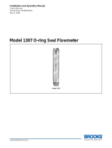
FLOAT TYPES AND ORIENTATIONS
7460 Series
Installation Instructions
Maximum Non-Shock Pressure and Temperature
Temperature Pressure
200° F (liquid)
250° F (gas)
200 psig
(41W-63W)
Ambient Temp. 33° F -125° F
GV FLOAT
(Rib Guided)
GV FLOAT
(Pole Guided)
GS FLOAT
(Rib Guided)
GS FLOAT
(Pole Guided)
LP FLOAT
SL FLOAT SP FLOAT
Pressure and temperature ratings are based on a study of the engineering data for
particular materials used in construction and on the design of individual models.
This information is supplemented by destructive test results. Meters with stainless
enclosures must never be operated without shields securely in place. Meters
exposed to difficult environments such as those created by certain chemicals,
excessive vibration or other stress inducing factors could fail at or below the
suggested maximums. Never operate meters above pressure and temperature
maximums. It is strongly recommended that all meter installations utilize an
appropriate pressure relief valve and/or rupture disc. The pressure settings and
locations of these devices should be such that meters cannot be over pressurized.
Meter failure could result in damage to equipment and serious personal injury.
Always use suitable safety gear, including OSHA approved eye protection when
working around meters in service. We are happy to pass along chemical
compatibility information that has been published by the manufacturer's of raw
materials used in our products; however, this information should not be construed
as a recommendation made by King Instrument Company, Inc. for a specific
application.
Carefully remove the flowmeter from piping system. Remove the 4 screws on each
side holding the side plates on. Remove the side plates. Carefully remove the glass
meter tube from the end fittings. Be sure to not let the internals fall out. Use caution
when removing the glass meter tube. Do not allow float to fall out. Float damage
may result in inaccuracy. All necessary instrument components are now fully
accessible for cleaning with a bottle brush and appropriate mild soap solution*.
Before the meter is reassembled, inspect all parts for damage. O-rings should be
replaced during meter maintenance and cleaning.
To reassemble, install the glass meter tube back onto the end fittings. Reinstall the
side plates. Tighten the 4 screws on each side. Reinstall the instrument into the
plumbing system after removing the old teflon tape (with a wire brush) and
replacing with fresh teflon tape.
*Do not use cleaning agents that will damage float, tube or o-rings.
Meters should be cleaned with a mild soap solution. This will be an effective
cleaner of rust stains. Caution must be used so that materials of construction are
not damaged by cleaning solutions. Hard water deposits can be removed with 5%
acetic acid solution (vinegar).
7460 meters that require repair should be sent to the factory. Please call for a
Return Merchandise Authorization (RMA) number and return instructions.
-O-rings should be replaced if meter is disassembled after it has been in service.
-Serious property damage and great personal injury could occur as the result of a
meter misused or used in an unsuitable application.
CAUTION:
CLEANING:
REPAIR:
WARNING:
FLOAT TYPES AND
ORIENTATIONS:
LP FLOAT
Maximum flow meter
capacity with limited
viscosity immunity
GV FLOAT (Rib Guided)
Highest immunity to
viscous fluids with
medium capacity.
SL FLOAT
Maximum flow meter
capacity with limited
viscosity immunity
GS FLOAT (Rib Guided)
Maximum flow meter
capacity with limited
viscosity immunity
SP FLOAT
Maximum flow meter
capacity with limited
viscosity immunity
GV FLOAT (Pole Guided)
Highest immunity to
viscous fluids with
medium capacity.
GS FLOAT (Pole Guided)
Maximum flow meter
capacity with limited
viscosity immunity