

Revision history Table of revisions
Date Changed Rev
September 2017 minor edit - Displacement limiter torque change 0202
November 2014 Danfoss layout BA
September 2010 New Back Page AD
March 2010 Fix Osaka address AC
March 2009 added spool alignment illustration AB
June 2008 First edition AA
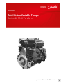
Service Manual
Series 40 M46 Tandem Variable Pumps
2 |
©
Danfoss | September 2017 11029852 | AX00000030en-US0202

Introduction
Overview..............................................................................................................................................................................................4
Warranty.............................................................................................................................................................................................. 4
General instructions........................................................................................................................................................................ 4
Safety precautions............................................................................................................................................................................4
Symbols used in Danfoss literature............................................................................................................................................6
Design...................................................................................................................................................................................................6
The system circuit.............................................................................................................................................................................7
Pump schematic............................................................................................................................................................................... 9
Fluid and filter maintenance
Fluid and filter recommendations........................................................................................................................................... 10
Initial startup procedures
General ..............................................................................................................................................................................................11
Start-up procedure........................................................................................................................................................................11
Pressure measurements
Required tools.................................................................................................................................................................................13
Port locations and gauge installation.....................................................................................................................................13
Troubleshooting
Overview........................................................................................................................................................................................... 15
Safety precautions.........................................................................................................................................................................15
System noise or vibration........................................................................................................................................................... 15
System operating hot...................................................................................................................................................................15
System will not operate in one direction.............................................................................................................................. 16
System will not operate in either direction.......................................................................................................................... 16
Neutral difficult or impossible to find.....................................................................................................................................17
System response is sluggish...................................................................................................................................................... 17
Electrical troubleshooting.......................................................................................................................................................... 18
Adjustments
Standard procedures, inspections, and adjustments....................................................................................................... 19
Warranty............................................................................................................................................................................................19
Pump adjustment..........................................................................................................................................................................19
Charge pressure relief valve.......................................................................................................................................................19
Engaging the bypass function.................................................................................................................................................. 20
System check/relief (SCR) valves.............................................................................................................................................. 21
Displacement limiter adjustment............................................................................................................................................ 22
Displacement limiter adjustment data.................................................................................................................................. 23
Swashplate neutral adjustment................................................................................................................................................23
Manual Displacement Control Bracket Neutral Adjustment..........................................................................................24
Electronic Displacement Control/Hydraulic Displacement Control Neutral Adjustment...................................25
Minor repair
Standard procedures, removing the pump..........................................................................................................................27
Displacement limiter.....................................................................................................................................................................27
Pressure filtration adapter.......................................................................................................................................................... 28
Charge pump...................................................................................................................................................................................29
Shaft seal...........................................................................................................................................................................................31
SCR valves.........................................................................................................................................................................................32
Charge pressure relief valve.......................................................................................................................................................33
Bypass valve.....................................................................................................................................................................................34
Manual displacement control....................................................................................................................................................35
Electronic Displacement Control/Hydraulic Displacement Control............................................................................36
MDC orifice repair..........................................................................................................................................................................38
EDC/HDC orifice repair.................................................................................................................................................................39
Torque chart
Fastener size and torque chart..................................................................................................................................................41
Plug size and torque chart..........................................................................................................................................................41
Service Manual
Series 40 M46 Tandem Variable Pumps
Contents
©
Danfoss | September 2017 11029852 | AX00000030en-US0202 | 3

Overview
This manual includes information for the installation, maintenance, and minor repair of the Series 40 M46
tandem pump. It includes a description of the unit and its individual components, troubleshooting
information, and minor repair procedures.
Performing minor repairs requires the unit to be removed from the vehicle/machine. Thoroughly clean
the unit before beginning maintenance, or repair activities. Since dirt and contamination are the greatest
enemies of any type of hydraulic equipment, follow cleanliness requirements strictly. This is especially
important when changing the system filter and when removing hoses or plumbing.
A worldwide network of Danfoss Global Service Partners is available for major repairs. Danfoss Global
Service Partners are trained by the factory and certified on a regular basis. You can locate your nearest
Global Service Partner using the distributor locator at www.sauer-danfoss.com.
Warranty
Performing installation, maintenance, and minor repairs according to the procedures in this manual will
not affect your warranty. Major repairs requiring the removal of a unit’s rear cover or front flange voids
the warranty unless done by a Danfoss Global Service Partner.
General instructions
Follow these general procedures when repairing Series 40 M46 tandem variable displacement closed
circuit pumps.
Remove the unit
Prior to performing major repairs, remove the unit from the vehicle/machine. Chock the wheels on the
vehicle or lock the mechanism to inhibit movement. Be aware that hydraulic fluid may be under high
pressure and/or hot. Inspect the outside of the pump and fittings for damage. Cap hoses after removal to
prevent contamination.
Keep it clean
Cleanliness is a primary means of assuring satisfactory pump life, on either new or repaired units. Clean
the outside of the pump thoroughly before disassembly. Take care to avoid contamination of the system
ports. Cleaning parts by using a clean solvent wash and air drying is usually adequate.
As with any precision equipment, all parts must be kept free of foreign materials and chemicals. Protect
all exposed sealing surfaces and open cavities from damage and foreign material. If left unattended,
cover the pump with a protective layer of plastic.
Replace all O-rings and gaskets
Replace all O-rings, gaskets and seals. Lightly lubricate all O-rings with clean hydraulic fluid or petroleum
jelly prior to assembly.
Safety precautions
Always consider safety precautions before beginning a service procedure. Protect yourself and others
from injury. Take the following general precautions whenever servicing a hydraulic system.
Service Manual
Series 40 M46 Tandem Variable Pumps
Introduction
4 |
©
Danfoss | September 2017 11029852 | AX00000030en-US0202

Unintended machine movement
W
Warning
Unintended movement of the machine or mechanism may cause injury to the technician or bystanders.
To protect against unintended movement, secure the machine or disable/disconnect the mechanism
while servicing.
Flammable cleaning solvents
W
Warning
Some cleaning solvents are flammable. To avoid possible fire, do not use cleaning solvents in an area
where a source of ignition may be present.
Fluid under pressure
W
Warning
Escaping hydraulic fluid under pressure can have sufficient force to penetrate your skin causing serious
injury and/or infection. This fluid may also be hot enough to cause burns. Use caution when dealing with
hydraulic fluid under pressure. Relieve pressure in the system before removing hoses, fittings, gauges, or
components. Never use your hand or any other body part to check for leaks in a pressurized line. Seek
medical attention immediately if you are cut by hydraulic fluid.
Personal safety
W
Warning
Protect yourself from injury. Use proper safety equipment, including safety glasses, at all times.
Hazardous material
W
Warning
Hydraulic fluid contains hazardous material. Avoid prolonged contact with hydraulic fluid. Always
dispose of used hydraulic fluid according to state, and federal environmental regulations.
Service Manual
Series 40 M46 Tandem Variable Pumps
Introduction
©
Danfoss | September 2017 11029852 | AX00000030en-US0202 | 5

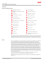
Symbols used in Danfoss literature
WARNING may result in injury Tip, helpful suggestion
CAUTION may result in damage to product or
property
Lubricate with hydraulic fluid
Reusable part Apply grease / petroleum jelly
Non-reusable part, use a new part Apply locking compound
Non-removable item Inspect for wear or damage
Option - either part may exist Clean area or part
Superseded - parts are not interchangeable Be careful not to scratch or damage
Measurement required Note correct orientation
Flatness specification Mark orientation for reinstallation
Parallelism specification Torque specification
External hex head Press in - press fit
Internal hex head Pull out with tool – press fit
Torx head Cover splines with installation sleeve
O-ring boss port Pressure measurement/gauge location or
specification
The symbols above appear in the illustrations and text of this manual. They are intended to communicate
helpful information at the point where it is most useful to the reader. In most instances, the appearance
of the symbol itself denotes its meaning. The legend above defines each symbol and explains its purpose.
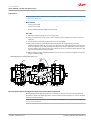
Design
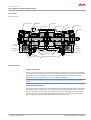
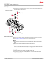
Danfoss Series 40 M46 closed circuit piston pumps convert input torque into hydraulic power. Rotational
force is transmitted through the input shaft to the cylinder block. The input shaft is supported by
bearings at the front and rear of the pump and is splined into the cylinder block. A lip-seal at the front
end of the pump prevents leakage where the shaft exits the pump housing. The spinning cylinder block
contains seven reciprocating pistons. Each piston has a brass slipper connected at one end by a ball joint.
The slippers are held to the swashplate by a spring washer and charge pressure. The reciprocating
movement of the pistons occurs as the slippers slide against the inclined swashplate during rotation. Via
the valve plate, one half of the cylinder block is connected to low pressure and the other half to high
pressure. As each piston cycles in and out of its bore, fluid is replenished by charge flow and displaced to
the outlet thereby imparting hydraulic power into the system. A small amount of fluid is allowed to flow
from the cylinder block/valve plate and slipper/swashplate interfaces for lubrication and cooling. Excess
flow across the charge pressure relief also flows through the case and is used for cooling. Case drain ports
return this fluid to the reservoir.
The volume of fluid displaced into the system is controlled by the angle of the swashplate. The
swashplate is forced into an inclined position (into stroke) by the servo piston.
The pump control, by varying the pressure at the servo piston, controls the displacement of fluid in the
system circuit.
Service Manual
Series 40 M46 Tandem Variable Pumps
Introduction
6 |
©
Danfoss | September 2017 11029852 | AX00000030en-US0202

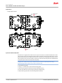
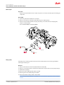
Cross section view
Piston
Slipper
Valve plate
Ball bearing
Gerotor
Shaft
Journal
bearing
Swashplate
bearing pin
Servo piston
Cylinder block
Manual displacement Control
Ball bearing
Slipper
Piston
Valve plate
Journal
bearing
Swashplate
bearing pin
Servo piston
Swashplate
P106665
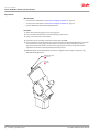
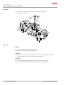
The system circuit
The basic closed circuit
The main ports of the pump are connected by hydraulic lines to the main ports of the motor. Fluid flows,
in either direction, from the pump to the motor then back to the pump in this closed circuit. Either of the
hydraulic lines can be under high pressure. In pumping mode the position of the pump swashplate
determines which line is high pressure as well as the direction of fluid flow.
A tandem circuit contains two pumps and motors. Each pump and motor circuit is similar to the one
shown.
Case drain and heat exchanger
The pump and motor case drain lines remove hot fluid from the system. The pump and motor should be
drained from their top most drain port to ensure the case remains full of fluid. The motor case drain can
be connected to the lower drain port on the pump housing and out the top most port or feed into the
case drain line coming from the pump ahead of the heat exchanger. A heat exchanger, with a bypass
valve, is required to cool the case drain fluid before it returns to the reservoir.
Service Manual
Series 40 M46 Tandem Variable Pumps
Introduction
©
Danfoss | September 2017 11029852 | AX00000030en-US0202 | 7

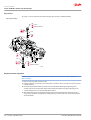
System circuit diagram
Input
shaft
Suction flow
Servo pressure
High pressure
Case flow
Charge pressure
Output
shaft
Cylinder
block
assembly
Filter
Charge
pump
Reservoir
Cylinder
block
assembly
Heat
exchanger
Check valves
w/ high pressure
relief valve
Variable
displacement
pump
Heat exchanger
bypass
Charge relief
valve
Displacement
control
valve
Control
handle
Bypass
valve
Loop flushing
module
P106608
Variable
displacement
motor
Service Manual
Series 40 M46 Tandem Variable Pumps
Introduction
8 |
©
Danfoss | September 2017 11029852 | AX00000030en-US0202

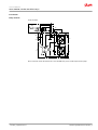
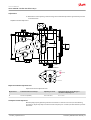
Pump schematic
Pump schematic
B
M2
M1
A
E
L1
L2
M5
M4
S
M3
B N A
P100 587E
Above schematic shows the function of a Series 40 M46 axial piston variable displacement pump.
Service Manual
S
eries 40 M46 Tandem Variable Pumps
Introduction
©
Danfoss | September 2017
11029852 | AX00000030en-US0202 | 9

Fluid and filter recommendations
To ensure optimum life, perform regular maintenance of the fluid and filter. Contaminated fluid is the
main cause of unit failure. Take care to maintain fluid cleanliness when servicing.
Check the reservoir daily for proper fluid level, the presence of water, and rancid fluid odor. Fluid
contaminated by water may appear cloudy or milky, or free water may settle in the bottom of the
reservoir. Rancid odor indicates the fluid has been exposed to excessive heat. Change the fluid
immediately if these conditions occur. Correct the problem immediately.
Inspect vehicle for leaks daily.
Change the fluid and filter per the vehicle/machine manufacturer’s recommendations or at these
intervals:
First fluid change recommended at 500 hours.
C
Caution
High temperatures and pressures will result in accelerated fluid aging. More frequent fluid changes may
be required.
Change the fluid more frequently if it becomes contaminated with foreign matter (dirt, water, grease,
etc.) or if the fluid is subjected to temperature levels greater than the recommended maximum.
Dispose of used hydraulic fluid properly. Never reuse hydraulic fluid.
Change filters whenever the fluid is changed or when the filter indicator shows that it is necessary to
change the filter. Replace all fluid lost during filter change.
Fluid and filter change interval
Reservoir type Max. oil change interval
Sealed 2000 hours
Breather 500 hours
Hazardous material
W
Warning
Hydraulic fluid contains hazardous material. Avoid contact with hydraulic fluid. Always dispose of used
hydraulic fluid according to state, and federal environmental regulations.
Service Manual
Series 40 M46 Tandem Variable Pumps
Fluid and filter maintenance
10 |
©
Danfoss | September 2017 11029852 | AX00000030en-US0202

General
Follow this procedure when starting-up a new pump installation or when restarting an installation in
which the pump has been removed and re-installed on a machine. Ensure pump has been thoroughly
tested on a test stand before installing on a machine.
W
Warning
Unintended movement of the machine or mechanism may cause injury to the technician or bystanders.
To protect against unintended movement, secure the machine or disable/disconnect the mechanism
while servicing.
Prior to installing the pump, inspect for damage that may have occurred during shipping.
Start-up procedure
1. Ensure that the machine hydraulic oil and system components (reservoir, hoses, valves, fittings, and
heat exchanger) are clean and free of any foreign material.
2. Install new system filter element(s) if necessary. Check that inlet line fittings are properly tightened
and there are no air leaks.
3. Install the pump. Install a 50 bar [1000 psi] gauge in the charge pressure gauge port M3.
4. Fill the housing by adding filtered oil in the upper case drain port.
5. Fill the reservoir with hydraulic fluid of the recommended type and viscosity. Use a 10-micron
reservoir filler filter. Ensure inlet line from reservoir to pump is filled.
6. Disconnect the pump from all control input signals.
7. Re-install plug or fitting removed in step 4.
After start-up the oil level in the reservoir may drop due to filling of the system components. Check
the level in the reservoir to maintain a full oil level throughout the start-up.
W
Warning
Damage to hydraulic components may occur if the oil supply is not maintained.
8. Use a common method to disable the engine to prevent the engine from starting. Crank the starter
for several seconds. Do not to exceed the engine manufacturer’s recommendation. Wait 30 seconds
and then crank the engine a second time as stated above. This operation helps remove air from the
system lines. Refill the reservoir to recommended full oil level.
9. When charge pressure begins to appear, enable and start engine. Let the engine run for a minimum
of 30 seconds at low idle to allow the air to work itself out of the system. Check for leaks at all line
connections and listen for cavitation. Check for proper fluid level in reservoir.
C
Caution
Air entrapment in oil under high pressure may damage hydraulic components.
C
Caution
Do not run at maximum pressure until system is free of air and fluid has been thoroughly filtered.
10. When adequate charge pressure is established (as shown in model code), increase engine speed to
normal operating rpm to further purge residual air from the system.
Service Manual
Series 40 M46 Tandem Variable Pumps
Initial startup procedures
©
Danfoss | September 2017 11029852 | AX00000030en-US0202 | 11

11. Shut off engine. Connect pump control signal. Start engine, checking to be certain pump remains in
neutral. Run engine at normal operating speed and carefully check for forward and reverse control
operation.
12. Continue to cycle between forward and reverse for at least five minutes to bleed all air and flush
system contaminants out of loop.
Normal charge pressure fluctuation may occur during forward and reverse operation.
13. Check that the reservoir is full. Remove charge pressure gauge. Re-install charge pressure plug. The
pump is now ready for operation.
Service Manual
Series 40 M46 Tandem Variable Pumps
Initial startup procedures
12 |
©
Danfoss | September 2017 11029852 | AX00000030en-US0202

Required tools
The service procedures described in this manual can be performed using common mechanic’s hand
tools. Special tools, if required, are shown. When testing system pressures, calibrate pressure gauges
frequently to ensure accuracy. Use snubbers to protect gauges.
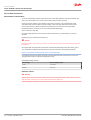
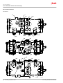
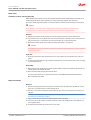
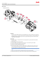
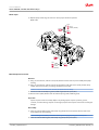
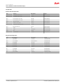
Port locations and gauge installation
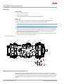
The following tables and drawing show the port locations and gauge sizes needed.
Port information
Port identifier Port size Wrench size Pressure obtained Gauge size, bar [psi]
L1, L2, L3 1-1/16 12 SAE 9/16 internal hex Case drain 10 [100]
MA, MB, MC, MD 9/16 18 SAE 11/16 hex System pressure 600 [10,000]
M3 9/16 18 UNF 11/16 hex Charge pressure 50 [1000]
M4, M5 9/16 18 SAE 11/16 hex Servo pressure 50 [1000]
System valves
Port identifier Relief Port size Wrench size
RA A port pressure relief valve 1-5/16 12 UNF 1-1/4 hex
RB B port pressure relief valve 1-5/16 12 UNF 1-1/4 hex
RC C port pressure relief valve 1-5/16 12 UNF 1-1/4 hex
RD D port pressure relief valve 1-5/16 12 UNF 1-1/4 hex
R Charge pressure relief valve 3/4 16 UNF 7/8 hex
BP Bypass valve 5/8 18 UNF 1 inch hex
System ports
Port identifier Port size
A system pressure port 1-5/16 12 SAE
B system pressure port 1-5/16 12 SAE
C system pressure port 1-5/16 12 SAE
D system pressure port 1-5/16 12 SAE
S (charge pressure inlet) 1-5/16 12 SAE
Service Manual
Series 40 M46 Tandem Variable Pumps
Pressure measurements
©
Danfoss | September 2017 11029852 | AX00000030en-US0202 | 13

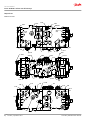
Port locations
M5
M4
RC
RB
A
B
L1
MA
MB
M3
MD
MC
S
C
D
M4
M5
RD
RA
L2
L3
BP
PB
R
P106663
Service Manual
Series 40 M46 Tandem Variable Pumps
Pressure measurements
14 |
©
Danfoss | September 2017 11029852 | AX00000030en-US0202

Overview
This section provides general steps to follow if undesirable system conditions are observed. Follow the
steps listed until the problem is solved. Some of the items will be system specific. For areas covered in
this manual, a section is referenced. Always observe the safety precautions listed in Introduction on page
4, and related to your specific equipment.
Safety precautions
C
Caution
High inlet vacuum causes cavitation which can damage internal pump components.
C
Caution
Contamination can damage internal components and void the manufacturer’s warranty. Take
precautions to ensure system cleanliness when removing and reinstalling system lines
System noise or vibration
Item Description Action
Reservoir oil level Low oil level leads to cavitation. Fill reservoir.
Aeration of the oil/pump inlet vacuum Air in system decreases efficiency of units and
controls. Air in system is indicated by excessive noise
in pump, foaming in oil, and hot oil.
Find location where air is entering into the
system and repair leak.
Check that inlet line is not restricted and is the
proper size.
Cold oil If oil is under cold conditions, it may be too viscous
for proper function and pump cavitates
Allow the oil to warm up to it’s normal operating
temperature with engine at idle speed.
Pump inlet vacuum High inlet vacuum causes noise/cavitation. Check that inlet line is not restricted and is the
proper size.
Check filter and bypass valve.
Shaft couplings A loose shaft coupling will cause excessive noise. Replace loose shaft coupling. Replace pump
shaft.
Shaft alignment Misaligned shafts creates noise Align shafts.
Charge/system relief valves Unusual noise may indicate sticking valves. Possible
contamination.
Clean/replace valves and test pump.
May be a normal condition.
System operating hot
Item Description Action
Oil level in reservoir Insufficient hydraulic fluid will not meet the
cooling demands of system.
Fill the reservoir to the proper level with clean
hydraulic oil.
Heat exchanger (if equipped) The heat exchanger is not sufficiently cooling the
system.
Check the air flow and input air temperature for
the heat exchanger. Clean, repair, or replace the
heat exchanger as necessary.
Bypass valve A partially activated bypass valve may result in heat
generation within the system.
Verify that the bypass valve is fully closed and that
the valve is seating properly. Repair or replace it as
necessary.
SCR (System Check / Relief) Valves A partially activated SCR valve or SCR valves with
relief settings too low may result in heat
generation within the system.
Verify that the SCR valve is seating properly and is
at the correct relief setting. Repair or replace it as
necessary.
Service Manual
Series 40 M46 Tandem Variable Pumps
Troubleshooting
©
Danfoss | September 2017 11029852 | AX00000030en-US0202 | 15

Item Description Action
Oil filters Clogged oil filters may result in an insufficient
supply of cool oil to the system.
Inspect the oil filters and verify that they are still
operable. Replace them if necessary.
Machine load Excessive loads or extreme duty cycles could result
in the pump and / or motor operating at speeds
and pressures beyond system design limitations.
Verify that the machine is operating within the
parameters for which it was designed. If necessary,
reduce the load on the machine.
System will not operate in one direction
Item Description Action
Input control signal (linkage, current, or
pressure)
A faulty control signal is being received at the
pump. (MDC - binding or broken linkage, EDC -
faulty or inadequate electrical signal, HDC -
blocked or incorrectly orificed control lines)
Verify that the input signal being received is
correct and identical in both directions. Adjust,
clean, repair, or replace the control module as
necessary.
SCR (system check / relief) valves The SCR valves are malfunctioning or improperly
set.
Verify that the SCR valves are operating properly.
Repair or replace them as necessary.
Pump control A damaged or biased pump control may be
sending a signal commanding the pump to stroke
only in one direction.
Verify that the pump’s control is functioning
properly. Repair or replace it as necessary.
Servo pressure The drain or supply path to one side of the servo
piston may be blocked.
Verify that the servo supply and drain paths are
unobstructed and that each orifice is of the correct
size and free of debris. Clean or repair them as
necessary.
Displacement limiters (if equipped) The displacement limiters may be improperly
adjusted such that the servo piston is prevented
from moving in one direction.
Verify that the displacement limiters are adjusted
properly.
System will not operate in either direction
Item Description Action
Oil level in reservoir There is insufficient hydraulic fluid to supply the
system loop.
Fill the reservoir to the proper level with clean
hydraulic oil.
Input control signal
(linkage, current, or pressure)
A faulty control signal being received at the pump.
(MDC - binding or broken linkage, EDC - faulty or
inadequate electrical signal, HDC - blocked or
incorrectly orificed control lines)
Verify that the input signal being received is
correct and identical in both directions. Adjust,
clean, repair, or replace the input device as
necessary.
Oil filters Clogged oil filters may result in an insufficient
supply of oil to the system.
Inspect the oil filters and verify that they are still
serviceable. Replace them as necessary.
Bypass valve A partially activated bypass valve may result in a
cross port leakage.
Verify that the bypass valves are closed and that
the valves are seating properly. Clean, repair, or
replace them as necessary.
Charge pressure
(in neutral)
Charge pressure may be insufficient to recharge
the system loop.
Inspect the charge pump for damage and verify
that the charge pressure relief valve is at the proper
setting. Repair or replace it as necessary.
Charge pressure
(in stroke)
There is low charge pressure resulting from internal
leakage within the system.
Repair or replace the component or components
within the system causing the internal leakage.
Servo pressure There is an insufficient pressure differential across
the servo piston.
Check servo pressures to verify sufficient pressure
delta. Verify that the servo supply and drain paths
are unobstructed and that each orifice is of the
correct size and free of debris. Clean, repair, or
replace them as necessary.
Charge pump The charge pump is damaged or has been installed
with the incorrect rotational orientation.
Verify that the charge pump is in good working
order and that it is correctly installed. Repair or
replace it as necessary.
Service Manual
Series 40 M46 Tandem Variable Pumps
Troubleshooting
16 |
©
Danfoss | September 2017 11029852 | AX00000030en-US0202

Item Description Action
SCR (system check / relief) valves The SCR valves are malfunctioning or improperly
set.
Verify that the SCR valves are operating and
properly set. Repair or replace them as necessary.
Displacement limiters Displacement limiters may be improperly adjusted
such that the servo piston is locked in place.
Verify that the displacement limiters are adjusted
to the proper setting.
Neutral difficult or impossible to find
Item Description Action
Input control signal (linkage, current, or
pressure)
A faulty control signal is being received at the
pump. (MDC - binding or broken linkage, EDC -
faulty or inadequate electrical signal, HDC -
blocked or incorrectly orificed control lines)
Verify that the input signal being received is
correct and identical in both directions. Adjust,
clean, repair, or replace control module as
necessary.
System pressure With no input signal to the control, a pressure delta
may exist between the two sides of the working
loop.
Readjust pump neutral setting. Refer to Swashplate
neutral adjustment on page 23.
Servo pressure With no input signal to the control, a pressure delta
may exist across the servo piston.
Readjust the control neutral setting. Refer to
Manual Displacement Control Bracket Neutral
Adjustment on page 24 and Electronic
Displacement Control/Hydraulic Displacement
Control Neutral Adjustment on page 25
PCP pressure (EDCs only) With no input signal to the control, a pressure
difference may exist across the control spool.
Replace the EDC.
System response is sluggish
Item Description Action
Reservoir oil level There is an insufficient amount of hydraulic fluid,
resulting in an inadequate supply for the system
loop.
Fill the reservoir to the proper level with clean
hydraulic fluid.
Input control signal
(linkage, current, or pressure)
A faulty control signal is being received at the
pump. (MDC - binding or broken linkage; EDC -
faulty or inadequate electrical signal; HDC -
blocked or incorrectly orificed control lines)
Verify that the input signal being received is correct
and identical in both directions.
Pump control A damaged pump control or control spool will not
correctly transmit the control input signal to the
pump.
Verify that the pump’s control is operating properly
and that the control spool is not damaged or worn
and moves freely within its bore. Clean, repair, or
replace it as necessary.
Bypass valve A partially activated bypass valve will cause cross
port leakage.
Verify that the bypass valve is closed and that the
valve is seating properly. Clean, repair, or replace it as
necessary.
SCR (system check / relief) valves One or both of the SCR valves may be binding
within their bores.
Verify that the SCR valves operate freely. Repair or
replace them as necessary.
Charge pressure (in neutral) There is low charge pressure resulting from a
damaged charge pump or low charge pressure
relief valve setting.
Inspect the charge pump for damage and verify the
charge pressure relief valve setting. Repair or replace
it as necessary.
Charge pressure (in stroke) There is low charge pressure resulting from internal
leakage within the system.
Repair or replace the component or components
within the system causing the internal leakage.
Service Manual
Series 40 M46 Tandem Variable Pumps
Troubleshooting
©
Danfoss | September 2017 11029852 | AX00000030en-US0202 | 17

Item Description Action
Servo pressure There is insufficient pressure differential across the
servo piston.
Check servo pressures at port M4 and M5 to verify
sufficient pressure delta. Verify that the servo supply
and drain paths are unobstructed and that each
orifice is of the correct size and free of debris. Clean,
repair, or replace as necessary.
Charge pump The charge pump has been damaged or installed
with the incorrect rotational orientation.
Verify that the charge pump is in good working order
and that it is correctly installed. Repair or replace it as
necessary.
Electrical troubleshooting
Item Description Action
Control operates pump in one direction
only
Control coil failure Measure resistance at coil pins. Resistance should be
14.20 ohms (24V) or 3.66 ohms (12V) at 20°C [70°F].
Replace coil
No pump function No power to controller Restore power to controller
Erratic pump function Electrical connection to pump is bad Disconnect connection, check wires, reconnect wires
Filter bypass indicator switch Filter switch may be bad Check/replace filter switch. Add gauge to filter
bypass port to verify proper fluid flow and verify
switch operation by measuring resistance.
open resistance=510 ohms, closed resistance=122
ohms
Service Manual
Series 40 M46 Tandem Variable Pumps
Troubleshooting
18 |
©
Danfoss | September 2017 11029852 | AX00000030en-US0202

Standard procedures, inspections, and adjustments
C
Caution
Contamination can damage internal components and void the manufacturer’s warranty. Take
precautions to ensure system cleanliness when removing and reinstalling system lines
1. With the prime mover off, thoroughly clean all dirt and grime from the outside of the pump.
2. If removing the pump, tag each hydraulic line connected to the pump. If hydraulic lines are
disconnected, plug each open port, to ensure that dirt and contamination do not get into the pump.
3. Ensure the surrounding areas are clean and free of contaminants such as dirt and grime.
4. Inspect the system for contamination.
5. Look at the hydraulic fluid for signs of system contamination, oil discoloration, foam in the oil, sludge,
or small metal particles.
6. Drain and flush the hydraulic system and replace all filters.
7. Before re-installing the pump, perform a leakage test per Sauer-Danfoss leakage test HPP 112.
Warranty
Performing installation, maintenance, and minor repairs according to the procedures in this manual will
not affect your warranty. Major repairs, requiring the removal of a unit’s rear cover or front flange, voids
the warranty unless done by a Danfoss Global Service Partner.
Pump adjustment
This section offers instruction on inspection and adjustment of pump components. Read through the
entire topic before beginning a service activity. Refer to Pressure measurements on page 13, for location of
gauge ports and suggested gauge size.
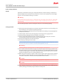
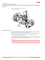
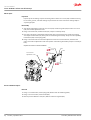
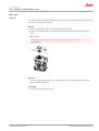
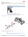
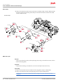
Charge pressure relief valve
The following procedure explains how to check and adjust the charge pressure relief valve.
1. Shut down prime mover.
2. Install a 50 bar [1000 psi] pressure gauge in charge pressure gauge port M3. Install a 10 bar [100 psi]
gauge in one of the case pressure ports L1 or L Operate the system with the pump in neutral (zero
displacement) to measure charge pressure.
Measure charge pressure at 1775 RPM. Charge pressure is found by subtracting case pressure from
the pressure measured at the charge pressure gage port M3.
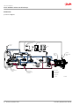
3. To adjust charge pressure, shut down prime mover.
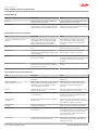
4. Using a 1 inch hex wrench, remove charge pressure relief plug (102). Add or remove shims (101) in
relief valve. Adding shims (101) increases charge pressure, while removing shims decreases charge
pressure. Refer to pump model code for the unit’s proper charge pressure setting.
5. Lubricate and install new O-ring O-ring (103).
6. Using a 1 inch hex wrench, reinstall plug (102). Torque to 108 Nm [80 ft•lb].
7. Operate pump in neutral to verify proper operation.
Service Manual
Series 40 M46 Tandem Variable Pumps
Adjustments
©
Danfoss | September 2017 11029852 | AX00000030en-US0202 | 19

8. Remove gages. Operate pump and check for leaks.
Charge pressure adjustment
P106 666E
103
105
104
101
102
1 in.
M3
11/16 in
Charge pressure
gage port
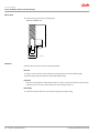
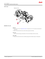
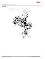
Engaging the bypass function
Test bypass function with pump installed on machine. The bypass function is engaged by unscrewing the
bypass valve. Do not open the bypass valve when machine is operating.
1. To engage the bypass function, use a 5/8 hex wrench to unscrew the bypass valve. Rotate the bypass
valve approximately three turns counterclockwise. Do not rotate more than 3 revolutions, as
additional rotation will permit external leakage.
2. To close the bypass valve, rotate the bypass valve clockwise until seated. Torque to 20 N•m [15 lbf•ft].
3. If machine is towable with bypass valve opened three turns, and if wheels are locked (not towable)
with bypass valve closed, bypass function is working correctly.
C
Caution
Avoid excessive speeds and extended load/vehicle movement. Do not move the load or vehicle more
than 20 % of maximum speed or for more than 3 minutes. Damage to drive motor(s) is possible.
Service Manual
Series 40 M46 Tandem Variable Pumps
Adjustments
20 |
©
Danfoss | September 2017 11029852 | AX00000030en-US0202
Page is loading ...
Page is loading ...
Page is loading ...
Page is loading ...
Page is loading ...
Page is loading ...
Page is loading ...
Page is loading ...
Page is loading ...
Page is loading ...
Page is loading ...
Page is loading ...
Page is loading ...
Page is loading ...
Page is loading ...
Page is loading ...
Page is loading ...
Page is loading ...
Page is loading ...
Page is loading ...
Page is loading ...
Page is loading ...
Page is loading ...
Page is loading ...
-
 1
1
-
 2
2
-
 3
3
-
 4
4
-
 5
5
-
 6
6
-
 7
7
-
 8
8
-
 9
9
-
 10
10
-
 11
11
-
 12
12
-
 13
13
-
 14
14
-
 15
15
-
 16
16
-
 17
17
-
 18
18
-
 19
19
-
 20
20
-
 21
21
-
 22
22
-
 23
23
-
 24
24
-
 25
25
-
 26
26
-
 27
27
-
 28
28
-
 29
29
-
 30
30
-
 31
31
-
 32
32
-
 33
33
-
 34
34
-
 35
35
-
 36
36
-
 37
37
-
 38
38
-
 39
39
-
 40
40
-
 41
41
-
 42
42
-
 43
43
-
 44
44


Ask a question and I''ll find the answer in the document
Finding information in a document is now easier with AI
Related papers
-
Danfoss S40 P User guide
-
Danfoss S42 P Installation guide
-
-
-
Danfoss S90 P User guide
-
-
-
-
-
Other documents
-
Signature Hardware 433866 Installation guide
-
Toro TX 427 Compact Utility Loader User manual
-
 Sauer Danfoss 45 Series User manual
-
Eaton 39 Repair Information
-
-
Toro 270-HE Lawn and Garden Tractor User manual
-
 Continental Hydraulics Vane Pump Installation guide
-
-
-
Eaton Electrical 350 User manual

