A.O. Smith 100344665 User manual
- Category
- Water heaters & boilers
- Type
- User manual

Gas Tankless Water Heater
TM
Suitable for combination potable water heating and
space heating. Please refer to local codes for space-
heating compliance.
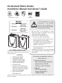
On-Demand Water Heater
Installation Manual and Owner’s Guide
If you have any questions, please
call or write to:
In the United States
500 Tennessee Waltz Parkway
Ashland City, TN 37015
Toll Free: 1-877-737-2840
In Canada
599 Hill Street West
Fergus, ON N1M 2X1
1-888-479-8324
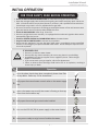
- Do not store or use gasoline or other
flammable vapors and liquids in the vicinity
of this or any other appliance.
- WHAT TO DO IF YOU SMELL GAS
• Donottrytolightanyappliance.
• Donottouchanyelectricswitch,donot
use any phone in your building.
• Immediatelycallyourgassupplierfrom
a neighbor's phone. Follow the gas
supplier's instructions.
• Ifyoucannotreachyourgassupplier,call
the fire department.
- Installation and service must be performed
by a qualified installer, service agency or the
gas supplier.
WARNING
If the information in these
instructions is not followed
exactly, a fire or explosion may
result causing property damage,
personal injury or death.
ANSI Z21.10.3 ・ CSA 4.3
540
model only
R
DR
Keep this manual near the water heater for future reference whenever maintenance, adjustment, or
service is required.
FEATURING
• ENDLESS HOT WATER
• ON-DEMAND USAGE
• COMPACT, SPACE SAVING
• ENERGY CONSERVATION
• COMPUTERIZED SAFETY
• NO PILOT LIGHT
• Complies with SCAQMD Rule
1146.2 for natural gas Low NOx
Emissions of 14 ng/J or 20 ppm.
• EASY-LINK SYSTEM AND
• MULTI-UNIT SYSTEM
(540 model only)
Models
• 240Indoor
• 340Indoor
• 540Indoor
• 240Outdoor
(USAOnly)
• 340Outdoor
(USAOnly)
• 540Outdoor
(USAonly)

2 Page
Contents
CONTENTS
Installation Manual
SPECIFICATIONS .............................................4
INTRODUCTION ..........................................5
SAFETY GUIDELINES.....................................6
SAFETY DEFINITION ....................................6
GENERAL ......................................................6
INSTALLATION ................................................7
GENERAL ......................................................7
CLEARANCES ...............................................9
INCLUDED ACCESSORIES ............................9
OPTIONAL ITEMS ........................................ 9
WARNING FOR INSTALLATIONS ...............11
.............12
VENTING INSTRUCTIONS .........................13
General .....................................................13
Combustion air supply ..............................14
Exhaust vent (ABS,PVC,CPVC, or
polypropylene vent) .................................18
DIP switch settings for vent length
(ABS,PVC,CPVC, or polypropylene vent) ...19
Exhaust vent (Stainless steel vent) ...........22
DIP switch settings for vent length
(Stainless steel vent) .................................22
Common venting system ..........................24
Vent termination clearances ....................26
Clearances for sidewall terminations .......27
Clearances for rooftop terminations ........28
GAS SUPPLY AND GAS PIPE SIZING ......... 29
General .....................................................29
Gas connections .......................................29
Natural Gas supply piping .........................30
Propane (LP) supply piping ....................... 30
Measuring inlet gas pressure ...................51
WATER CONNECTIONS .............................31
Pressure relief valve .................................31
CONDENSATE DRAIN ................................32
Condensate drain connections .................32
ELECTRICAL CONNECTIONS .....................34
TEMPERATURE REMOTE CONTROLLER .....35
Included accessories .................................35
Installation ................................................35
.........................................37
Easy link connection procedures ..............37
......................................39
APPLICATIONS ..............................................40
Space heating applications ......................... 40
Recirculation ...............................................40
Dual-purpose hot water heating ................... 41
INITIAL OPERATION .....................................42
Owner's Guide
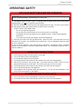
OPERATING SAFETY .....................................44
NORMAL OPERATION ..................................46
AND REMOTE CONTROLLER ..................46
GENERAL ....................................................46
OUTLET WATER TEMPERATURE
SETTING ..................................................... 47
TEMPERATURE TABLE OF CONTROLLER .47
ADDITIONAL FEATURES ...................... ......48
Information mode ....................................48
Unit conversion mode ..............................48
TEMPERATURE SETTINGS ON THE PCB ........49
FLOW .......................................................... 49
FREEZE PROTECTION SYSTEM ................. 50
MAINTENANCE AND SERVICE ................. 51
Measuring inlet gas pressure ...................51
UNIT DRAINING AND FILTER CLEANING .......51
TROUBLESHOOTING .....................................52
GENERAL ....................................................52
ERROR CODES ...........................................53
General .......................................................53
Single unit installation ..............................54
Easy-Link System ....................................... 54
Fault analysis error code ..........................55
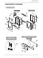
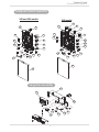
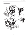
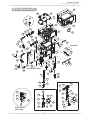
COMPONENTS DIAGRAM ............................57
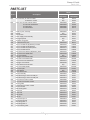
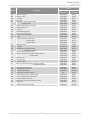
PARTS LIST .................................................... 61
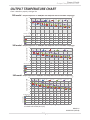
OUTPUT TEMPERATURE CHART ..................64

3 Page
Installaon Manual
Installation Manual
CONGRATULATIONS
Congratulations and thank you for choosing our tankless water heater.
Before use, we recommend that you read through this installation
If you need an additional manual, contact the manufacturer or your
local distributor. When you call, please tell us the product name and
the serial number of your unit written on the rating plate of the water
heater.

4 Page
Specicaons
Installaon Manual
SPECIFICATIONS
*40 psi or above is recommended for maximum flow.
**Water heater Category — water heaters of other than direct vent type, for outdoor installation, are divided into four
categories based on static pressure produced in the vent and flue loss.
Category I - a water heater that operates with a non-positive vent static pressure and with a vent gas temperature
that avoids excessive condensate production in the vent.
Category II - a water heater that operates with a non-positive vent static pressure and with a vent gas temperature
that may cause excessive condensate production in the vent.
Category III - a water heater that operates with a positive vent static pressure and with a vent gas temperature that
avoids excessive condensate production in the vent.
Category IV - a water heater that operates with a positive vent static pressure and with a vent gas temperature that
may cause excessive condensate production in the vent.
NOTE:
The manufacturer reserves the right to discontinue, or change at any time, specifications or designs
without notice and without incurring obligation.
Model
240
Indoor
240
Outdoor
340
Indoor
340
Outdoor
540
Indoor
540
Outdoor
Natural Gas Input
(Operating Range)
BTU/h
Min.: 15,000
Max.: 160,000
Min.: 15,00
Max.: 180,000
Min.: 15,000
Max.: 199,000
Propane Input
(Operating Range)
BTU/h
Min.: 13,000
Max.: 160,000
Min.: 13,000
Max.: 180,000
Min.: 13,000
Max.: 199,000
Gas Connection 3/4" NPT
Water Connections
3/4" NPT
Water Pressure* psi (MPa) 15 - 150 (0.1 - 1)
Natural gas
Inlet Pressure
" W.C.
(kPa)
Min. 4.0 (1.00)
Max. 10.5 (2.61)
Propane
Inlet Pressure
" W.C.
(kPa)
Min. 8.0 (1.99)
Max. 14.0 (3.48)
Weight lbs. (kg)
58 (26.3) 58 (26.2) 58 (26.3) 58 (26.2) 59 (26.8) 59 (26.9)
Dimensions
inch
H 22.4 x W 17.7 x D 10.7
H 570 x W 450 x D 272
mm
Ignition Electric Ignition
Electric
Supply
VAC/Hz 120/60
Consumption
Operation W/A 72.7 / 0.61 78.2 / 0.65 89.0 / 0.74
Standby W/A 3.1 / 0.03 3.1 / 0.03 4.2 / 0.04
Freeze-
Protection
W/A 174 / 1.5 174 / 1.5 175 / 1.5
Water heater category**
Category
IV
N/A
Category
IV
N/A
Category
IV
N/A

5 Page
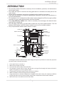
INTRODUCTION
This manual provides information necessary for the installation, operation, and maintenance
of the water heater.
The model description is listed on the rating plate which is attached to the side panel of the
water heater.
Please read all installation instructions completely before installing this product.
If you have any problems or questions regarding this equipment, consult the manufacturer or
its local representative.
This equipment is an on-demand, tankless water heater designed to efficiently supply endless
hot water for your needs when properly sized and installed.
These high efficiency models have a built-in secondary heat exchanger that absorbs latent
heat from the exhaust gas.
The 240 Indoor, 340 Indoor, and 540 Indoor models are only to be installed indoors. The 240
Outdoor, 340 Outdoor, and 540 Outdoor models are only to be installed outdoors.
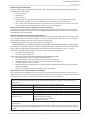
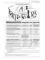
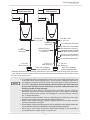
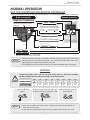
The principle behind tankless water heaters is simple:
Exhaust
Secondary
heat exchanger
Intake port
Condensate
drain port
Cold water inlet
Gas
Hot water outlet
Computer board
Fan motor
Gas valves
Igniter
Thermistor
Thermistor
Bypass valve
Primary
heat exchanger
Exhaust thermistor
Water control valve
Thermistor
Flow sensor
Burners
1
2
3
4
5
4
6
7
7
7
8
4
4
7
*This diagram illustrates tankless water heater design concepts only and does not accurately represent
the water heater’s physical description.
1. A hot water fixture is turned on.
2. Water flows through the heater.
3. The water flow sensor detects the water flow.
4. The computer initiates the fan motor and gas valve to let gas flow through the heater and sends a
signal to the igniter to create an ignition spark.
5. The gas ignites and flames appear within the burner chamber.
6. Water is heated as it flows through the heat exchanger.
7. Using thermistors to measure temperatures throughout the water heater, the computer modulates
the gas and water valves to ensure proper output water temperature and hot water outflows.
8. When the fixture is turned off, the unit shuts down.
Introducon
Installaon Manual

6 Page
GENERAL
1. Follow all local codes, or in the absence of local codes, follow the current edition of the National
Fuel Gas Code: ANSI Z223.1/NFPA 54 in the USA or B149.1 Natural Gas, Propane Installation Code in
Canada.
2. Properly ground the unit in accordance with all local codes or in the absence of local codes, with the
National Electrical Codes: ANSI/NFPA 70 in the USA or CSA standard C22.1 Canadian Electrical Code
Part 1 in Canada.
3. Carefully plan where you intend to install the water heater. Please ensure:
Your water heater will have enough combustible air and proper ventilation.
Locate your heater where water leakage will not damage surrounding areas. (Please refer to p. 8.)
4. Check the rating plate for the correct GAS TYPE, GAS PRESSURE, WATER PRESSURE and ELECTRIC
RATING.
*If this unit does not match your requirements, do not install and consult with the manufacturer.
5. If any problem should occur, turn off all hot water taps and turn off the gas. Then call a trained
technician, the gas company, or the manufacturer.
Safety Guidelines
Installaon Manual
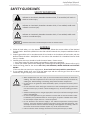
SAFETY GUIDELINES
SAFETY DEFINITION
WARNING
Indicates an imminently hazardous situation which, if not avoided, could result
in death or serious injury.
CAUTION
Indicates an imminently hazardous situation which, if not avoided, could result
in minor or moderate injury.
Indicates an imminently hazardous situation which, if not avoided, will result in
death or serious injury.
DANGER
Indicates information considered important but not hazard related.
NOTICE
WARNING
Water temperatures over 125 °F (52 °C) can cause severe burns instantly or death from
scalding. The water temperature is set at 120 °F (50 °C) from the factory to minimize any
scalding risk. Before bathing or showering always check the water temperature.
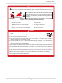
Do not store or use gasoline or other flammables, vapors, or liquids in the vicinity of this
appliance.
Do not reverse the water and/or gas connections as this will damage the gas valves and
can cause severe injury or death. Follow the diagram on p. 31 when installing your water
heater.
Should overheating occur or the gas supply fails to shut off, turn off the manual gas control
valve to the appliance.
Do not use this appliance if any part has been in contact with or been immersed in water.
Immediately call a qualified installer or service agency to replace a flooded water heater.
Do not attempt to repair the unit. It must be replaced.
Do not disconnect the electrical supply if the ambient temperature will drop below
freezing. The Freeze Protection System only works if the unit has electrical power. The
warranty will not be covered if the heat exchanger is damaged due to freezing. Refer to
the section on the Freeze Protection System on p. 50 for more information.
Failure to observe these warnings could result in severe personal injury or death.

7 Page
INSTALLATION
GENERAL
1. Follow all local codes, or in the absence of local codes, follow the current edition of the National
Fuel Gas Code: ANSI Z223.1/NFPA 54 in the USA or B149.1 Natural Gas, Propane Installation Code
in Canada.
2. All gas water heaters require careful and correct installation to ensure safe and efficient operation.
This manual must be followed exactly. Read the “Safety Guidelines” Section.
3. The manifold gas pressure is preset at the factory. It is computer controlled and should not need
adjustment.
4. Maintain proper space for servicing. Install the unit so that it can be connected or removed easily.
Refer to the "Clearances" Section on p. 9 for proper clearances.
5. The water heater must be installed in a location where the proper amount of combustible air will
be available to it at all times without obstructions, or the indoor heater may be direct vented.
6. Electrical service to the water heater requires a means of disconnection. This will allow power to
the water heater to be shut off for servicing and safety purposes.
7. Do not install the unit where the exhaust vent is pointing into any opening in a building or where
the noise may disturb your neighbors. Make sure the vent termination meets the required
clearance from any doorway or opening to prevent exhaust from entering a building. (Refer to pp.
11, 26 and 27.) Check local code requirements prior to installation.
8. Carefully plan the installation location of the heater and vent terminations. Contaminants such as
aerosols, lint, and fine powders (including flour) can clog the air intake and reduce the operation
of the fan. This, in turn, can cause improper combustion and reduce the life of the water heater.
Regularly ensure that the area around the water heater, vent termination, and air intake is free of
dust, debris, and other contaminants. In environments with a high level of contaminants (laundry
facilities, hair salons, pet salons, chemical plants, commercial kitchens, etc.), direct venting is
required.
9. The 240 Indoor, 340 Indoor, and 540 Indoor are to be installed indoors only. These units are
equipped with a thermistor and hi-limit switch for the exhaust gas, detecting excess temperatures
within the flue and enabling the unit to safely stop operations if needed. These components are
always monitoring exhaust gas conditions in order to prevent heat damage to ABS, PVC, CPVC,
or polypropylene (Plastic) venting if ABS, PVC, CPVC, or polypropylene is used. If the exhaust
gas temperature exceeds 140 °F (60 °C), these components will enable the unit to safely stop
operations. These components are not installed on the outdoor models since the exhaust vent
is built-in.
If the water heater is used as a direct-vent appliance, the unit requires 3 in (76 mm) or 4 in
(102 mm) combustion air supply pipe. The intake pipe must be sealed airtight. Refer to pp.
13 to 28 for more detail.
Terminating the venting through a sidewall is recommended for the direct-vent system.
Running the exhaust vent and the intake pipe parallel is recommended.
Terminating the exhaust and intake on the same wall/surface is recommended. Terminating in
the same pressure zone allows for pressure balancing, which prevents nuisance shutdowns.
Only install the water heater in a heated area where below freezing temperatures cannot
occur. The warranty does not cover damage caused by freezing.
The water heater must be securely mounted to a wall or other suitable structure.
10. The 240 Outdoor, 340 Outdoor, and 540 Outdoor models must only be installed outdoors and only
in an area with mild, temperate climates. The Outdoor model shall be wall-mounted or mounted
on a stand. Locate the Outdoor model in an open, unroofed area and maintain the following
minimum clearances: There is a 3 in. (76 mm) clearance from the left and right sides of the unit
to combustible and non-combustible surfaces.
Installaon
Installaon Manual

8 Page
Installaon
Installaon Manual
Installation and service must be performed by a qualified installer (for example, a
licensed plumber or gas fitter). Otherwise, the warranty will be void.
The installer (licensed professional) is responsible for the correct installation of the
water heater and for compliance with all national, state/provincial, and local codes.
The manufacturer does not recommend installing the water heater in a pit or
location where gas and water can accumulate.
Do not have the vent terminal pointing toward any operating window, door, or
opening into a building.
Do not install next to any source of airborne debris, such as a clothes dryer, that
can cause debris to be trapped inside the combustion chamber, unless the system is
direct-vented.
Do not install the unit where water, debris, or flammable vapors may get into the flue
terminal or the air intake line.
The manufacturer does not recommend installing the water heater in an attic due
to safety issues. If you install the water heater in an attic:
Make sure the unit will have enough combustion air and proper ventilation.
Failure to do so could lead to carbon monoxide poisoning or death.
sensor, the water heater will shut down on an error code.
Place the unit where it will allow easy access for service and maintenance.
A drain pan, or other means of protection against water damage, is
recommended to be installed under the water heater in case of leaks.
Failure to observe these warnings could result in severe personal injury, death,
and/or property damage.
WARNING
The warranty will not cover damage caused by water quality.
Only potable water can be used with this water heater. Do not introduce pool
or spa water, or any chemically treated water into the water heater.
Water hardness levels must not exceed 7 grains per gallon (120 ppm) for
single family domestic applications or more than 4 grains per gallon (70 ppm)
for all other types of applications. Water hardness leads to scale formation
and may affect/damage the water heater. Hard water scaling must be avoided
or controlled by proper water treatment.
Water pH levels must be between 6.5 and 8.5.
Well water must be treated.
The manufacturer recommends direct venting when the water heater is installed
in beauty salons, dry cleaners or any other locations in which such chemicals
are present in the air. Some chemicals used in beauty salons or dry cleaners may
affect the flame sensor. In such cases, the water heater may not work properly.
Although the water heater is designed to operate with minimal sound, the
manufacturer does not recommend installing the unit on a wall adjacent to a
bedroom, or a room that is intended for quiet study or meditation, etc.
Locate your heater close to a drain where water leakage will not do damage to
surrounding areas. As with any water heating appliance, the potential for leakage
at some time in the life of the product does exist. The manufacturer will not be
responsible for any water damage that may occur. If you install a drain pan under
the unit, ensure that it will not restrict the combustion air flow.
NOTICE

9 Page
CLEARANCES
Installaon
Installaon Manual
Model Top Bottom Front Back Sides
240 Indoor
340 Indoor
540 Indoor
12 in.
(305 mm)
12 in.
(305 mm)
4 in.*
(102 mm)
0.5 in.
(13 mm)
3 in.
(76 mm)
240 Outdoor
340 Outdoor
540 Outdoor
36 in.
(914 mm)
12 in.
(305 mm)
24 in.
(610 mm)
0.5 in.
(13 mm)
3 in.
(76 mm)
*24 inches recommended for maintenance.
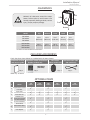
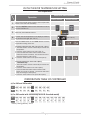
OPTIONAL ITEMS
Back
Side
Front
Side
Top
#
Model
240
Indoor
240
Outdoor
340
Indoor
340
Outdoor
540
Indoor
540
Outdoor
1.
Temperature remote
controller
✓ ✓ ✓
2.
Pipe cover
✓ ✓ ✓ ✓ ✓ ✓
3.
Neutralizer kit
✓ ✓ ✓ ✓ ✓ ✓
4.
Sidewall vent
terminator (Hood)
and Wall thimble
✓ ✓ ✓
5.
3" PVC concentric
termination
✓ ✓ ✓
6.
Non-return valve
✓ ✓ ✓
7.
PVC Adapter
✓ ✓ ✓
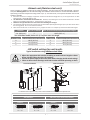
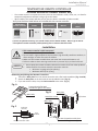
INCLUDED ACCESSORIES
Check that these items below are included with the water heater.
Installation manual
and owner’s guide
Temperature remote controller kit*
Outdoor models only
Bird screen
Indoor models only
Communication cable
540 model only
Qty: 1
Qty: 1
Qty: 1
*Refer to p. 10 and 35.
Qty: 2
100209924
(TM-RE42)
Maintain all clearances around the water
heater. Failure to do so could create a fire
hazard, potentially leading to death, serious
injury, and/or property damage.
WARNING

10 Page
Installaon
Installaon Manual
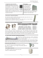
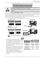
3. Neutralizer kit: 100112159 (TH-NT01)
The neutralizer assembly neutralizes the condensate (acidic water) that forms in the
secondary heat exchanger of the water heater.
It connects to the condensate drain port of the water heater by using connectors
included with the neutralizer kit. (Refer to pp. 32 and 33.)
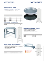
1. Temperature remote controller:
100209924 (TM-RE42)-Standard model
The temperature remote controllers have
three functions. It allows the output
temperature from the water heater to be
adjusted and it also works as a diagnostic
tool and it provides a concise error code
whenever there is a problem with the unit. See the
Troubleshooting Section (pp.53 to 56) for information
on possible error codes.
5. 3" PVC concentric termination: 100112163 (TH-CVPVC33)
Used when terminating direct-vent (sealed combustion)
systems, with Indoor models that require a 3 in. (76 mm) intake
and a 3 in. (76 mm) exhaust.
2. Pipe cover:
100112718 (TH-PC03)
The pipe cover protects
the plumbing pipes to
the water heater from
unexpected adjustments.
This pipe cover is fixed
to the bottom of the
water heater, which hides the plumbing and
improves the visual aspects of the whole
installation for the water heater.
4. Sidewall vent terminator (Hood) and Wall thimble:
These are used when venting out through the wall. These terminations are special stainless steel
vents for gas appliances and are UL listed as Category II, III and IV. For different wall thicknesses, there
are two ranges of lengths available. (Refer to the NovaVent brochure for details.) Install these vent
terminations in accordance with their installation instructions and any applicable local codes.
Wall Thimble
Terminator Hood
6. Non-return valve: 100113130
7. PVC Adapter: 100113129
It is a must-have item for common venting system. It prevents
the escape of combustion gas through non-operating appliances.
(Refer to p. 24 and 25.)
This adapter transitions from the Non-return valve
outlet to 4" schedule 40 PVC pipe.
This concentric termination provides the convenience of only having to make one penetration through a
sidewall instead of two separate penetrations for the intake and exhaust piping. The termination includes
a bird screen, restricting small animals, pests, and foreign objects from entering into the vent system.
Covering wall thicknesses Part#
Terminator Hood 100112419
Wall Thimble 4 - 7 in (102 - 178 mm) 100112732
Wall Thimble 5 - 10 in (123 - 254 mm) 100112733
Termination + Thimble 4 - 7 in (102 - 178 mm) 100112424
Termination + Thimble 5 - 10 in (123 - 254 mm) 100112425

11 Page
Installaon
Installaon Manual
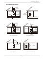
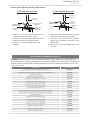
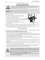
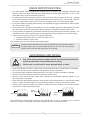
WARNING FOR INSTALLATIONS
FOR YOUR SAFETY, READ BEFORE INSTALLATION:
Do not install the heater where water, debris or
flammable vapors may get into the flue terminal.
This may cause damage to the heater and void the
warranty.
Do not have the vent terminal pointing toward
any opening into a building. Do not locate your
heater in a pit or location where gas and water
can accumulate.
Do not install this water heater under an
overhang less than 3 ft (914 mm) from its top
or eaves. The area under an overhang must be
open to three sides (Outdoor model only).
Do not install next to a dryer or any source
of airborne debris that can be trapped inside
the combustion chamber, unless the system is
direct-vented.
Prohibited
Prohibited
3 ft
(914 mm)
Water heater vent terminator must be at least 2
ft (610 mm) away from an inside corner for both
outdoor installation and direct-vent installation.
Inside
Corner
2 ft
(610 mm)
USA: 1 (30 cm) min.
Canada: 3 (91 cm) min.
USA: 1 (30 cm) min.
Canada: 3 (91 cm) min.
USA: 1 (30 cm) min.
Canada: 3 (91 cm) min.
USA: 12 in. (30 cm) above grade and
above ancipated snow level
Canada: 12 in. (30 cm) above grade
Ancipated snow level
Ensure that you meet the minimum clearances
shown below for a direct vent termination:

12 Page
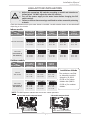
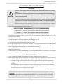
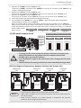
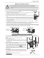
HIGH-ALTITUDE INSTALLATIONS
WARNING
• Adjust the appropriate DIP switches according to model and elevation as
shown below. DO NOT adjust the other DIP switches.
• Turn off the power supply to the water heater before changing the DIP
switch settings.
• Failure to observe these warnings could lead to carbon monoxide poisoning
or death.
Check the elevation where your water heater is installed. Set DIP switches shown in the table below
depending on the altitude.
Installaon
Installaon Manual
NOTE: The dark squares indicate the correct DIP switch positions.
540 model computer board
Lower bank of DIP switches
Bank of DIP switches
240 and 340 models computer board
Indoor models
0 to 2,000 ft
(0 to 610 m)
(DEFAULT)
2,000 to
3,000 ft
(611 to 914 m)
3,000 to
5,000 ft
(915 to 1,524 m)
5,000 to
7,500 ft
(1,525 to 2,286 m
7,500 to
10,100 ft
(2,287 to 3,078 m)
240 and 340 models
OFF
ON
1 2 3 4 5 6 7 8 9 10
No. 3 : OFF
No. 4 : OFF
No. 5 : OFF
OFF
ON
1 2 3 4 5 6 7 8 9 10
No. 3 : OFF
No. 4 : ON
No. 5 : OFF
OFF
ON
1 2 3 4 5 6 7 8 9 10
No. 3 : OFF
No. 4 : OFF
No. 5 : ON
OFF
ON
1 2 3 4 5 6 7 8 9 10
No. 3 : OFF
No. 4 : ON
No. 5 : ON
OFF
ON
1 2 3 4 5 6 7 8 9 10
No. 3 : ON
No. 4 : ON
No. 5 : ON
540 model
(Lower bank of
DIP switches)
OFF
ON
1 2 3 4 5 6
No. 2 : OFF
No. 3 : OFF
No. 4 : OFF
OFF
ON
1 2 3 4 5 6
No. 2 : OFF
No. 3 : ON
No. 4 : OFF
OFF
ON
1 2 3 4 5 6
No. 2 : OFF
No. 3 : OFF
No. 4 : ON
OFF
ON
1 2 3 4 5 6
No. 2 : OFF
No. 3 : ON
No. 4 : ON
OFF
ON
1 2 3 4 5 6
No. 2 : ON
No. 3 : ON
No. 4 : ON
Altitude
DIP switches
Installation altitude
The maximum certified
or allowable installed
altitude is 10,100 ft
(3,078 m) for indoor
models and 6,000 ft
(1,829 m) for outdoor
models.
Outdoor models
0 to 2,000 ft
(0 to 610 m)
(DEFAULT)
2,000 to
4,000 ft
(611 to 1,219 m)
4,000 to
6,000 ft
(1,220 to 1,829 m)
240 and
340 models
OFF
ON
1 2 3 4 5 6 7 8 9 10
No. 3 : OFF
No. 4 : OFF
No. 5 : OFF
OFF
ON
1 2 3 4 5 6 7 8 9 10
No. 3 : OFF
No. 4 : OFF
No. 5 : ON
OFF
ON
1 2 3 4 5 6 7 8 9 10
No. 3 : ON
No. 4 : OFF
No. 5 : ON
540 model
(Lower bank of
DIP switches)
OFF
ON
1 2 3 4 5 6
No. 2 : OFF
No. 3 : OFF
No. 4 : OFF
OFF
ON
1 2 3 4 5 6
No. 2 : OFF
No. 3 : OFF
No. 4 : ON
OFF
ON
1 2 3 4 5 6
No. 2 : ON
No. 3 : OFF
No. 4 : ON
Altitude
DIP switches

13 Page
Installaon
Installaon Manual
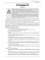
VENTING INSTRUCTIONS
Indoor models
-General-
WARNING
Improper venting of this appliance can result in excessive levels of carbon
monoxide which can result in severe personal injury or death.
Improper installation can cause nausea or asphyxiation, severe injury or death
from carbon monoxide and flue gases poisoning. Improper installation will void
product warranty.
When installing the vent system, all applicable national and local codes must be
followed. If you install thimbles, fire stops or other protective devices and they
penetrate any combustible or noncombustible construction, be sure to follow
all applicable national and local codes.
The Indoor model must be vented in accordance with “Venting of Equipment" in the current edition of the
National Fuel Gas Code: ANSI Z223.1/NFPA 54 in the United States and/or Section 8 of the B149.1 Natural
Gas and Propane Installation Code in Canada, as well as applicable local building codes.
The use of venting materials approved for Category III/IV appliances is recommended whenever possible.
However, the Indoor model may also be vented with plastic pipe materials such as ABS, PVC (solid core),
CPVC (solid core), or polypropylene. For details, please refer to the Exhaust Vent (ABS, PVC, CPVC, or
Polypropylene Vent) Section on p. 18. Vent installations in Canada which utilize plastic vent systems must
use venting that complies with ULC S636.
General rules for venting water heaters:
Place the water heater as close as possible to the vent termination.
The vent collar of the water heater must be fastened directly to an unobstructed vent pipe.
Do not weld the vent pipe to the water heater’s vent collar.
Do not cut or alter the vent collar of the unit.
The vent must be easily removable from the top of the water heater for normal service and inspection of
the unit.
The water heater vent must not be connected to any other gas appliance or vent stack except an approved
common-venting system. Refer to pp. 24 and 25.
Avoid using an oversized vent pipe or using extremely long runs of the pipe unless it is part of an approved
common vent system.
Air supply pipe can be made of ABS, PVC (solid core), CPVC (solid core), polypropylene, corrugated stainless
steel, or Category lll / IV stainless steel. Regarding exhaust pipe, refer to pp.18 to 23.
Use of cellular core PVC (ASTM F891), cellular core CPVC, or Radel® (polyphenylsulfone) in nonmetallic
venting systems is prohibited. Covering non-metallic vent pipe and fittings with thermal insulation is
prohibited.
Sidewall venting is recommended for the Indoor model. Vertical venting (roof termination) is acceptable.
The manufacturer recommends running the exhaust vent and the intake pipe as parallel as possible.
For rooftop venting, a rain cap or other form of termination that prevents rain water from entering into
the water heater must be installed.
Do not terminate vent into a chimney. If the vent must go through the chimney, the vent must run all the
way through the chimney with approved vent pipe.
The water heater shall not be connected to a chimney flue serving a separate appliance, designed to burn
solid fuel.
General rules for vent terminations:
Avoid locating the water heater vent termination near any air intake devices. These fans can pick up the
exhaust flue products from the water heater and return them to the building. This can create a health
hazard.
Locate the vent termination so that it cannot be blocked by any debris, at any time. Most codes require
that the termination be at least 12 in (305 mm) above grade and anticipated snow level, but the installer
may determine if it should be higher depending on the job site condition and applicable codes.
A proper sidewall termination is recommended when the water heater is vented through a sidewall.
Regarding the clearances from the exhaust termination to the air inlet or opening, refer to pp. 26 to 28.

14 Page
-Combuson air supply-
This gas water heater requires an adequate source of clean air for combustion and
ventilation. Without sufficient air, your water heater may not operate properly and
may emit excessive and abnormal amounts of carbon monoxide which may result in
carbon monoxide poisoning or death.
WARNING
• The guidelines in this section apply to installations within the United States. All
U.S. installations must conform to the National Fuel Gas Code, ANSI Z223.1/NFPA
54 (current edition) and local codes.
• Canadian requirements differ from the guidelines in this section. In Canada,
follow the requirements of B149.1 (Natural Gas and Propane Installation Code,
current edition) as well as local and provincial codes. Contact your local code
enforcement agency for direction.
NOTICE
Before installing the water heater, you must determine the amount of air needed to supply this water
-
Check for Chemicals:
these corrosive chemicals is not covered by the warranty.
WARNING!
In all cases, ensure that corrosive chemicals are not present at the air intake. Presence of such chemicals
require outside air due to chemicals include:
Beauty salons
Photo processing labs
Indoor pools
Chemical storage areas
Products such as aerosol sprays, detergents, bleaches, cleaning solvents, gasoline, air fresheners, paint and
varnish removers, and refrigerants should not be stored or used near the water heater.
Does your installation space have sufficient combustion air?
-
ing appliances (e.g., water heaters, furnaces, clothes dryers) in the same area. Do not include appliances
that are direct vented. Refer to the following example.
Installaon
Installaon Manual

15 Page
Your water heater’s BTU/h rating is on the rating plate. The BTU/h ratings should be on the other
appliances’ rating plates. If you have trouble determining the BTU/h ratings, contact the manufacturer
or have a qualified person determine the ventilation requirements.
NOTICE:
Gas Burning Appliance
Gas Water Heater 199,000
Furnace 75,000
Dryer 20,000
Total 294,000
Example:
Gas Burning Appliance
Gas Water Heater
Total
Your
appliances:
Calculate the air volume of the room
Air requirements depend on the size of the room.
3
2
If there are large objects in the room (e.g., refrigerator, furnace, car), subtract their volume from the vol-
Air Volume = Room Volume - Object Volume
Calculate required air volume
3
(1.42 m
3
) per 1,000 BTU/h of the total input for all gas burning appliances in the same area.
3
3
/ 1000 (btu/h)
Example:
3
If the air volume of the room is less than the required air volume, you must direct vent the water heater
-
If the air volume of the room is greater than the required air volume, it may be possible to install the
as furnaces, whole house fans, and clothes dryers draw air out of your home. If they draw air out faster
-
”
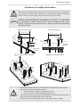
Install with outside ventilation
Supplying outside air to the water heater typically requires two openings. One opening must be within 12 in
single opening is not preferred, you may use a single opening to outside air if the minimum free area is sized
according to Table 1
Installaon
Installaon Manual

16 Page
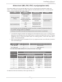
Determine type of ventilation
1. Direct to outdoors
2.
3. Horizontal ducts
4. Single opening (not recommended; must be at least 100 in
2
(6.5 cm
2
3
(1.42 m
3
5. From a larger room inside the house (not recommended – refer to "Calculate the air volume of the room"
above to determine if the combined volume of the rooms may be adequate).
Determine minimum free area required for each vent opening
from “Before beginning”) and the type of vent used. Table 1 provides the minimum free area for each vent opening
Calculate minimum size of vent openings and ducts
vents use louvers or grilles to protect the opening. The louver or grill itself blocks some of the free area, so the open-
ing may need to be larger to meet the minimum free area requirements.
2
(645 cm
2
) of free area would need
134 in
2
(865 cm
2
2
2
).
Each vent opening must be no smaller than 100 in
2
(645 cm
2
).
Rectangular ducts must have a minimum dimension of no less than 3 in (76 mm).
All screens must have mesh ¼” or larger.
-
Check that air source is clean and free of chemicals
-
See graphics on next page.
Table 1
indoor spaces.
Opening Source Minimum Free Area
Direct to outdoors*
1 in
2
(6.5 cm
2
) per 4,000 BTU/hr (see Figure 1, 2)
1 in
2
(6.5 cm
2
) per 4,000 BTU/hr (see Figure 3)
Horizontal ducts
1 in
2
(6.5 cm
2
) per 2,000 BTU/hr (see Figure 4)
Single Opening
1 in
2
(6.5 cm
2
) per 3,000 BTU/hr (see Figure 5)
Two permanent openings
to another room**
1 in
2
(6.5 cm
2
) per 1,000 Btu/hr (see Figure 6)
Opening: 100 in
2
(645 cm
2
) MIn
Minimum dimension of air openings:
no less than 3 in (76 mm)
an outside wall.
-
Installaon
Installaon Manual

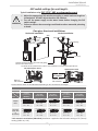
17 Page
Gable vent
to outdoors
Install above
insulaon
Outlet air to
ac 1 in
2
(6.5 cm
2
)
per 4,000 btu/h
Inlet air from
the crawl space
Open foundaon vent
Confined
Space
Alternate
Air Inlet
1 in
2
(6.5 cm
2
)
per 4,000 btu/h
Figure 1 - Direct to outdoors openings
duct openings
Outlet air to
ac 1 in
2
(6.5 cm
2
)
per 4,000 btu/h
Inlet air duct
1 in
2
(6.5 cm
2
)
per 4,000 btu/h
Confined
Space
12” (305 mm)
maximum
Gable vent
to outdoors
Install above
insulaon
Figure 5 - SIngle opening
Confined
Space
1 in
2
(6.5 cm
2
)
per 3,000 btu/h
Alternave
Opening
Locaon
Figure 6 - Two permanent openings
Two permanent
Openings
1 in
2
per
1,000 btu/h
12” (305 mm)
maximum
12” (305 mm)
maximum
Confined
Space
Figure 4 - Horizontal duct openings
1 in
2
(6.5 cm
2
)
per 2,000 btu/h
Confined
Space
Outlet
Inlet
Outdoor
Air Ducts
1 in
2
(6.5 cm
2
)
per 2,000 btu/h
Figure 2 - Direct to outdoors openings
Two permanent openings
Two permanent
Openings
1 in
2
(6.5 cm
2
)
per 4,000 btu/h
12” (305 mm)
maximum
12” (305 mm)
maximum
Confined
Space
Installaon
Installaon Manual

18 Page
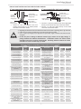
-Exhaust vent (ABS, PVC, CPVC, or polypropylene vent)-
The Indoor models can be vented with ABS, PVC, CPVC, or polypropylene (temperature rated up to
149 °F). Vent material certified to ULC S636 standards is recommended in the USA. In Canada, plastic
venting must be certified to ULC S636 standards.
The maximum length of exhaust vent piping must not exceed 70 ft (21.3 m) for 3” venting, which
depends on the elevation where the water heater is installed, and 100 ft (30.5 m) for 4” venting
(deducting 5 ft (1.5 m) for each elbow used in the venting system). Do not use more than 5
elbows. See the table below.
When the horizontal vent run exceeds 5 ft (1.5 m), support the vent run at 3 ft (0.9 m) intervals
with overhead hangers.
Installaon
Installaon Manual
Item Material United States Canada
Exhaust pipe and
Fittings
Schedule 40 PVC ANSI/ASTM D1785
ULC S636 Certified
Materials Only
PVC-DWV ANSI/ASTM D2665
Schedule 40 CPVC ANSI/ASTM F441
Schedule 40 ABS-DWV ANSI/ASTM D2661
Polypropylene UL-1738
Pipe Cement/Primer
PVC ANSI/ASTM D2564
CPVC ANSI/ASTM F493
ABS ANSI/ASTM D2235
Use of cellular core PVC (ASTM F891), cellular core CPVC, or Radel® (polyphenylsulfone) in
non-metallic venting systems is prohibited.
Covering non-metallic vent pipe and fittings with thermal insulation is prohibited.
Diameter Max. No. of Elbows Max. Vertical and Horizontal (Total) Vent Length
3 in. (76 mm) 5 70 ft (21.3 m)
4 in. (102 mm) 5 100 ft (30.5 m)
*For each elbow added, deduct 5 ft. (1.5 m) from max. vent length.
No. of Elbows
Max. Vertical or Horizontal (Total) Vent Length
3" (76 mm) venting
4" (102 mm)
venting
0 to 3,000 ft
(0 to 914 m)
3,001 to 6,000 ft
(915 to 1,829 m)
6,001 to 10,100 ft
(1,830 to 3,078 m)
0 to 10,100 ft
(0 to 3,078 m)
0 70 ft (21.3 m) 40 ft (12.2 m) 25 ft (7.6 m) 100 ft (30.5 m)
1 65 ft (19.8 m) 35 ft (10.7 m) 20 ft (6.1 m) 95 ft (29.0 m)
2 60 ft (18.3 m) 30 ft (9.1 m) 15 ft (4.6 m) 90 ft (27.4 m)
3 55 ft (16.8 m) 25 ft (7.6 m) 10 ft (3.0 m) 85 ft (25.9 m)
4 50 ft (15.2 m) 20 ft (6.1 m) N/A 80 ft (24.4 m)
5 45 ft (13.7 m) N/A N/A 75 ft (22.9 m)
Excludes vent terminators, termination elbows, or rain caps.
For details on the vent connection, refer to pp. 20 and p. 21.

19 Page
Installaon
Installaon Manual
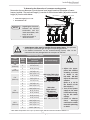
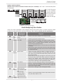
-DIP switch settings for vent length-
PVC, CPVC, ABS, or polypropylene vent
WARNING
Adjust the appropriate DIP switches according to model and vent length as
shown below. DO NOT adjust the other DIP switches.
Turn off the power supply to the water heater before changing the DIP
switch settings.
Failure to observe these warnings could lead to carbon monoxide poisoning
or death.
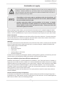
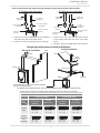
Roof
Fire stop
Wall
Connect between exhaust vent collar and piping.
Hanger
Hanger
For details of the optional items, refer to the Installation manual for each optional item.
Set DIP switches shown in the table below depending on the vent diameter and length.
DIP switch settings : Two-pipe, Direct vent installations
Vent diameter
3" (76 mm) venting* 4" (102 mm) venting
5 to 20 ft
(1.5 to 6.1m)
(DEFAULT)
21 to 40 ft
(6.2 to 12.2 m)
41 to 70 ft
(12.3 to 21.3 m)
5 to 50 ft
(1.5 to 15.2m)
(DEFAULT)
51 to 100 ft
(15.3 to 30.5 m)
240/340
Indoor
OFF
ON
1 2 3 4 5 6 7 8 9 10
No. 6 : O N
No. 7 : OFF
OFF
ON
1 2 3 4 5 6 7 8 9 10
No. 6 : OFF
No. 7 : OFF
OFF
ON
1 2 3 4 5 6 7 8 9 10
No. 6 : O N
No. 7 : O N
OFF
ON
1 2 3 4 5 6 7 8 9 10
No. 6 : O N
No. 7 : OFF
OFF
ON
1 2 3 4 5 6 7 8 9 10
No. 6 : OFF
No. 7 : OFF
540 Indoor
(Upper bank
of
DIP switches)
OFF
ON
1 2 3 4 5 6 7 8
No. 3 : O N
No. 4 : OFF
OFF
ON
1 2 3 4 5 6 7 8
No. 3 : OFF
No. 4 : OFF
OFF
ON
1 2 3 4 5 6 7 8
No. 3 : O N
No. 4 : O N
OFF
ON
1 2 3 4 5 6 7 8
No. 3 : O N
No. 4 : OFF
OFF
ON
1 2 3 4 5 6 7 8
No. 3 : OFF
No. 4 : OFF
Vent
length
Model
*PVC concentric termination (100112163) installation is applied to the DIP switch settings of 3" (76 mm)
venting. (Refer to p. 10.)
240 340 Computer board
Bank of
DIP switches
540 Computer board
Upper bank of
DIP switches
Lower bank of
DIP switches

20 Page
Installaon
Installaon Manual
1. Connect 3" (76 mm) couplings directly on the exhaust
and intake vent collar of the water heater.
2. Connect 3" (76 mm) straight pipes to the couplings.
1. Connect 3"x 4" (76 x 102 mm) increasers directly
on the exhaust and intake vent collar of the water
heater.
2. Connect 4" (102 mm) straight pipes to the increasers.
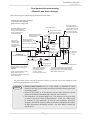
<Howtoinstallintakeandexhaustventing(two-pipe,direct-vent)withtheindoormodels>
3"(76mm)ventconnecon 4"(102mm)ventconnecon
<Single-pipewithroom-airintakeinstallaon>
HorizontalInstallaon
VercalInstallaon
Roof
Fire stop
Connect between exhaust vent collar and piping.
See the instrucons below.
Roof
ashing
Elbow
Elbow
Wall
Hanger
For details of the optional items, refer to the Installation manual for each optional item.
DIP switch settings : Single vent pipe installations
Vent diameter
3" (76 mm) venting* 4" (102 mm) venting
5 to 45 ft
(1.5 to 13.7m)
(DEFAULT)
46 to70 ft
(13.8 to 21.3 m)
5 to 50 ft
(1.5 to 15.2m)
(DEFAULT)
51 to 100 ft
(15.3 to 30.5 m)
240/340
Indoor
OFF
ON
1 2 3 4 5 6 7 8 9 10
No. 6 : O N
No. 7 : OFF
OFF
ON
1 2 3 4 5 6 7 8 9 10
No. 6 : OFF
No. 7 : OFF
OFF
ON
1 2 3 4 5 6 7 8 9 10
No. 6 : O N
No. 7 : OFF
OFF
ON
1 2 3 4 5 6 7 8 9 10
No. 6 : OFF
No. 7 : OFF
540 Indoor
(Upper bank
of
DIP switches)
OFF
ON
1 2 3 4 5 6 7 8
No. 3 : O N
No. 4 : OFF
OFF
ON
1 2 3 4 5 6 7 8
No. 3 : OFF
No. 4 : OFF
OFF
ON
1 2 3 4 5 6 7 8
No. 3 : O N
No. 4 : OFF
OFF
ON
1 2 3 4 5 6 7 8
No. 3 : OFF
No. 4 : OFF
Vent
length
Model
Set DIP switches shown in the table below depending on the vent diameter and length.
Exhaust vent collar
(Female)
3" (76 mm) coupling
(included)
Intake vent collar
(Female)
3"(76 mm)
straight pipe
3" (76 mm)
straight pipe
3" (76 mm) coupling
(included)
Exhaust vent collar
(Female)
Intake vent collar
(Female)
3"x 4"
(76 x 102 mm)
increaser
3"x 4"
(76 x 102 mm)
increaser
4" (102 mm)
straight pipe
4" (102 mm)
straight pipe
Page is loading ...
Page is loading ...
Page is loading ...
Page is loading ...
Page is loading ...
Page is loading ...
Page is loading ...
Page is loading ...
Page is loading ...
Page is loading ...
Page is loading ...
Page is loading ...
Page is loading ...
Page is loading ...
Page is loading ...
Page is loading ...
Page is loading ...
Page is loading ...
Page is loading ...
Page is loading ...
Page is loading ...
Page is loading ...
Page is loading ...
Page is loading ...
Page is loading ...
Page is loading ...
Page is loading ...
Page is loading ...
Page is loading ...
Page is loading ...
Page is loading ...
Page is loading ...
Page is loading ...
Page is loading ...
Page is loading ...
Page is loading ...
Page is loading ...
Page is loading ...
Page is loading ...
Page is loading ...
Page is loading ...
Page is loading ...
Page is loading ...
Page is loading ...
-
 1
1
-
 2
2
-
 3
3
-
 4
4
-
 5
5
-
 6
6
-
 7
7
-
 8
8
-
 9
9
-
 10
10
-
 11
11
-
 12
12
-
 13
13
-
 14
14
-
 15
15
-
 16
16
-
 17
17
-
 18
18
-
 19
19
-
 20
20
-
 21
21
-
 22
22
-
 23
23
-
 24
24
-
 25
25
-
 26
26
-
 27
27
-
 28
28
-
 29
29
-
 30
30
-
 31
31
-
 32
32
-
 33
33
-
 34
34
-
 35
35
-
 36
36
-
 37
37
-
 38
38
-
 39
39
-
 40
40
-
 41
41
-
 42
42
-
 43
43
-
 44
44
-
 45
45
-
 46
46
-
 47
47
-
 48
48
-
 49
49
-
 50
50
-
 51
51
-
 52
52
-
 53
53
-
 54
54
-
 55
55
-
 56
56
-
 57
57
-
 58
58
-
 59
59
-
 60
60
-
 61
61
-
 62
62
-
 63
63
-
 64
64


A.O. Smith 100344665 User manual
- Category
- Water heaters & boilers
- Type
- User manual
Ask a question and I''ll find the answer in the document
Finding information in a document is now easier with AI
Related papers
-
Takagi GTS-540P-NIH, GTS-540P-PIH, GT-540P-NEH, GT-540P-PEH User manual
-
State 100282551 User manual
-
Takagi 100123396 Owner's manual
-
Takagi T-H3-DV Installation Manual And Owner's Manual
-
A.O. Smith ATI-540H-N Technical Documents
-
Takagi T-KJr2U-IN/OS Owner's manual
-
Takagi 100227698 Installation guide
-
State Water Heaters 710 Installation Manual And Owner's Manual
-
Takagi T?KJr2?OS Owner's manual
-
A.O. Smith ATI-310U-N Technical Documents
Other documents
-
Enviro Mini Freestanding Pellet Stove User manual
-
Takagi GTS-140-NIH, GTS-240-NIH, GTS-340-NIH, GTS-540-NIH, GTS-140-NEH, GTS-240-NEH, GTS-340-NEH, GTS-540-NEH, GTS-140-PEH, GTS-140-PIH, , GTS-240-NIH , GTS-240-PIH , GTS-340-NIH , GTS-340-PIH , GTS-540-NIH , GTS-540-PIH , GTS-540P-NIH , GTS-540P-PIH Owner's manual
-
-
State GTS-540P-NIH, GTS-540P-PIH, GT-540P-NEH, GT-540P-PEH User manual
-
Lennox TUA100S User manual
-
 The Plumber's Choice 21GWHS User manual
-
State Industries GTS-110-NI, GTS-110-NE, GTS-310-NI, GTS-310-NE, GTS-510-NI, GTS-510-NE, GTS-910, GTS-910-ASME User manual
-
Takagi T-H2-IN/OS Owner's manual
-
Noritz America EZTR40-LP Installation guide
-
Rinnai Sensei RUR199i Installation guide
