A.O. Smith ATI-310U-N Technical Documents

Category
Water heaters & boilers
Type
Technical Documents
Gas Tankless Water Heater
TM
Suitable for potable water heating and space-heating*
* Please refer to local codes for space-heating compliance.
FEATURING
• ENDLESSHOTWATER
• ON-DEMANDUSAGE
• COMPACT,SPACESAVING
• ENERGYCONSERVATION
• COMPUTERIZEDSAFETY
• NOPILOTLIGHT
• Satisfiesthe2012SCAQMDRule
1146.2forUltra-LowNOx
Emissions
• EASY-LINKSYSTEMAND
MULTI-UNITSYSTEM
(510U (T-D2U) models only)
Models
510U(T-D2U)
modelsonly
Ifyouhaveanyquestions,please
callorwriteto:
500TennesseeWaltzParkway
AshlandCity,TN37015
TollFree:1-877-737-2840
WARNING
- Do not store or use gasoline or other
flammablevaporsandliquidsinthevicinity
ofthisoranyotherappliance.
- WHATTODOIFYOUSMELLGAS
 • Donottrytolightanyappliance.
 • Donottouchanyelectricswitch,donot
useanyphoneinyourbuilding.
 • Immediatelycallyourgassupplierfrom
aneighbor'sphone.Followthegas
supplier'sinstructions.
 • Ifyoucannotreachyourgassupplier,call
thefiredepartment.
- Installation and service must be performed
byaqualifiedinstaller,serviceagencyorthe
gassupplier.
On-Demand Water Heater
Installation Manual and Owners Guide
ANSIZ21.10.3andCSA4.3
If the information in these
instructions is not followed
exactly,afireorexplosionmay
resultcausingpropertydamage,
personalinjuryordeath.
• 110U Outdoor (T-KJr2U-OS)
• 310U Outdoor (T-K4U-OS)
• 510U Outdoor (T-D2U-OS)
• 110U Indoor (T-KJr2U-IN)
• 310U Indoor (T-K4U-IN)
• 510U Indoor (T-D2U-IN)
2 Page
CONTENTS
Installation Manual
SPECIFICATIONS.......................................................................................................................... 4
 INTRODUCTION.......................................................................................................................... 5
 SAFETYGUIDELINES.................................................................................................................... 6
 INSTALLATION............................................................................................................................. 7
  General.....................................................................................................................................7
  Clearances................................................................................................................................9
  IncludedAccessories...............................................................................................................9
  OptionalItems........................................................................................................................9
  WarningforInstallations..........................................................................................................9
  High-altitudeInstallations......................................................................................................12
  VentingInstructions...............................................................................................................13
  Gassupplyandgaspipesizing...............................................................................................18
  WaterConnections................................................................................................................20
  ElectricalConnections............................................................................................................21
  TemperatureRemoteController...........................................................................................22
  Easy-linkSystem.....................................................................................................................25
  Multi-UnitSystem..................................................................................................................29
 APPLICATIONS............................................................................................................................30
 INITIALOPERATION...................................................................................................................32
Owner's Guide
OPERATINGSAFETY.................................................................................................................. 34
 NORMALOPERATION............................................................................................................... 36
  General..................................................................................................................................36
  TemperatureSettings.............................................................................................................37
  Flow.......................................................................................................................................40
  Freezeprotectionsystem.......................................................................................................40
  Maintenanceandservice.......................................................................................................41
  UnitDrainingFilterCleaning..................................................................................................41
 TROUBLESHOOTING...................................................................................................................42
  General...................................................................................................................................42
  ErrorCodes...........................................................................................................................44
 COMPONENTSDIAGRAM...........................................................................................................47
 PARTSLIST.................................................................................................................................51
 OUTPUTTEMPERATURECHART................................................................................................54
 LIMITEDWARRANTY..................................................................................................................55
3 Page
Contents
Installaon Manual
Installation Manual
CONGRATULATIONS
Congratulationsandthankyouforchoosingourtanklesswaterheater.
Beforeuse,werecommendthatyoureadthroughthissafetymanual
carefully.Pleaserefertothebackofthemanualfordetailsaboutthe
warranty.Keepthismanualforfuturereference.
If you lose the manual, contact the manufacturer or your local
distributor. When you call, please tell us the product name and the
serial number of your unit written on the rating plate of the water
heater.
4 Page
Model
110U
Indoor
(T-KJr2U-IN)
110U
Outdoor
(T-KJr2U-OS)
310U
Indoor
(T-K4U-IN)
310U
Outdoor
(T-K4U-OS)
510U
Indoor
(T-D2U-IN)
510U
Outdoor
(T-D2U-OS)
Natural Gas Input
(OperatingRange)
BTU/h
Min.:15,000
Max.:140,000
Min.:15,000
Max.:190,000
Min.:15,000
Max.:199,000
Gas Connection 3/4"NPT
Water Connections 3/4"NPT
Water Pressure*
psi
(Mpa)
15-150(0.1-1)
Natural gas
Inlet Pressure
"W.C.
(kPa)
Min.5.0(1.24)
Max.10.5(2.61)
Manifold
Pressure**
Natural
Gas
"W.C.
(Pa)
1.8
(448)
1.5
(373)
3.0
(747)
2.9
(722)
3.3
(821)
2.9
(722)
Weight lbs.(kg) 37(16.9) 39(17.9)
Dimensions
inch
H20.5xW13.8xD8.5
H520xW351xD216
mm
Ignition ElectricIgnition
Electric
Supply VAC/Hz 120/60
Consumption
Operation W/A 52.1/0.54 75.8/0.83 81.6/0.86
Standby W/A 5.4/0.08 5.5/0.08 6.5/0.09
Freeze-
Protection
W/A 131/1.1 131/1.1 132/1.1
SPECIFICATIONS
*40psioraboveisrecommendedformaximumflow.
**TheManifoldPressureisthefactorysettingandgenerallyshould not need adjustment.
NOTE:
• Checktheratingplatetoensurethisproductmatchesyourspecifications.
• InaccordancewithANSIZ21.10.3,COemissiondoesnotexceed400PPMfornormalinput.
• The manufacturer reserves the right to discontinue, or change at any time, specifications or designs
without notice and without incurring obligations.
Specicaons
Installaon Manual
5 Page
INTRODUCTION
• Thismanualprovidesinformationnecessaryfortheinstallation,operation,andmaintenance
ofthewaterheater.
• Themodeldescriptionislistedontheratingplatewhichisattachedtothefrontpanelofthe
waterheater.
• Pleasereadallinstallationinstructionscompletelybeforeinstallingthisproduct.
• Ifyouhaveanyproblemsorquestionsregardingthisequipment,consultwiththemanufacturer
oritslocalrepresentative.
• Thisequipmentisanon-demand,tanklesswaterheaterdesignedtoefficientlysupplyendless
hotwaterforyourneeds.
• The110U Indoor (T-KJr2U-IN),310U Indoor(T-K4U-IN)and 510UIndoor(T-D2U-IN) models
are to be installed indoor (direct-vent convertible). The 110U Outdoor (T-KJr2U-OS), 310U
Outdoor(T-K4U-OS)and510UOutdoor(T-D2U-OS)modelsaretobeonlyinstalledoutdoor.
• Theprinciplebehindtanklesswaterheatersissimple:
 *Thisdiagramillustratestanklesswaterheaterdesignconceptsonlyanddoesnotaccurately
representthewaterheatersphysicaldescription.
1. Ahotwatertapisturnedon.
2. Waterenterstheheater.
3. Thewaterflowsensordetectsthewaterflow.
4. Thecomputerinitiatesthefanmotorandsendsasignaltotheignitertocreateanignitionspark.
5. Thegasignitesandflamesappearwithintheburnerchamber.
6. Watercirculatesthroughtheheatexchangerandthengetshot.
7. Usingthermistorstomeasuretemperaturesthroughoutthewaterheater,thecomputermodulates
thegasandwatervalvestoensureproperoutputwatertemperature.
8. Whenthetapisturnedoff,theunitshutsdown.
Burners
Introducon
Installaon Manual
Exhaustventcollar
Heatexchanger
Gasvalves
Fanmotor
Flowadjustmentvalve
Computerboard
Thermistor
ColdwaterinletHotwateroutlet
Gasinlet
Thermistor
Burners
Flowsensor
6 Page
SAFETY GUIDELINES
SAFETY DEFINITION
GENERAL
1. Followalllocalcodes,orintheabsenceoflocalcodes,followthemostrecenteditionoftheNational
FuelGasCode:ANSIZ223.1/NFPA54intheUSAorCAN/CSAB149.1NaturalGasInstallationCode
inCanada.
2. Properlygroundtheunitinaccordancewithalllocalcodesorintheabsenceoflocalcodes,withthe
NationalElectricalCodes:ANSI/NFPA70intheUSAorCSAstandardC22.1CanadaElectricalCode
Part1inCanada.
3. Carefullyplanwhereyouintendtoinstallthewaterheater.Pleaseensure:
Yourwaterheaterwillhaveenoughcombustibleairandproperventilation.
Locateyourheaterwherewaterleakagewillnotdamagesurroundingareas(pleasereferto
p.8).
4. ChecktheratingplateforthecorrectGAS TYPE, GAS PRESSURE, WATER PRESSURE and ELECTRIC
RATING.
*Ifthisunitdoesnotmatchyourrequirements,do not install and consult with the manufacturer.
5. Ifanyproblemshouldoccur,turnoffallhotwatertapsandturnoffthegas.Thencallatrained
technicianortheGasCompanyorthemanufacturer.
WARNING
• Watertemperaturesover125°F(52°C)cancausesevereburnsinstantlyor
deathfromscalding.Thewatertemperatureissetat120°F(49°C)fromthe
factory to minimize any scalding risk. Before bathing or showering always
checkthewatertemperature.
• Do not store or use gasolineor other flammables,vapors,or liquids in the
vicinityofthisappliance.
• Donotreversethewaterand/orgasconnectionsasthiswilldamagethegas
valvesandcancausesevereinjuryordeath.Followthediagramonp.20when
installingyourwaterheater.
• Do not use this appliance if any part has been in contact with or been
immersedinwater.Immediatelycallalicensedplumber,alicensedgasfitter,
or a professional service technician to inspect and/or service the unit if
necessary.
• Do not disconnect the electrical supply if the ambient temperature will
drop below freezing. The Freeze Prevention System only works if the unit
haselectricalpower.Thewarrantywillnotbecoverediftheheatexchanger
is damaged due to freezing. Refer to the section on the Freeze Prevention
Systemonp.39formoreinformation.
WARNING
Indicatesanimminentlyhazardoussituationwhich,ifnotavoided,couldresult
indeathorseriousinjury.
CAUTION
Indicatesanimminentlyhazardoussituationwhich,ifnotavoided,couldresult
inminorormoderateinjury.
Safety Guidelines
Installaon Manual
Indicatesanimminentlyhazardoussituationwhich,ifnotavoided,willresultin
deathorseriousinjury.
DANGER
7 Page
INSTALLATION
GENERAL
1. Followalllocalcodes,orintheabsenceoflocalcodes,followthemostrecenteditionoftheNational
FuelGasCode:ANSIZ223.1/NFPA54intheUSAorCAN/CSAB149.1NaturalGasInstallationCodein
Canada.
2. Allgaswaterheatersrequirecarefulandcorrectinstallationtoensuresafeandefficientoperation.This
manualmustbefollowedexactly.Readthe“SafetyGuidelines”section.
3. The manifold gas pressure is preset at the factory. It is computer controlled and should not need
adjustment.
4. Maintainproperspacefor servicing. Installthe unit sothatit can beconnectedor removed easily.
Refertothe"Clearances"sectiononp.9forproperclearances.
5. Thewaterheatermustbeinstalledinalocationwheretheproperamountofcombustibleairwillbe
availabletoitatalltimeswithoutobstructions.
6. Theelectricalconnectionrequiresameansofdisconnection,toterminatepowertothewaterheater
forservicingandsafetypurposes.
7. Donotinstalltheunitwheretheexhaustventispointingintoanyopeninginabuildingorwherethe
noisemay disturb your neighbors.Makesurethe vent termination meetstherequireddistanceby
localcodefromanydoorwayoropeningtopreventexhaustfromenteringabuilding(refertop.14).
8. Particlesfromflour,aerosols,andothercontaminantsmayclogtheairventorreducethefunctions
oftherotatingfanandcauseimproperburningofthegas.Regularlyensurethattheareaaroundthe
unitisdust-ordebris-free;regularmaintenanceisrecommendedforthesetypesofenvironment.
9. Ifyouwillbeinstallingthewaterheaterinacontaminatedareawithahighlevelofdust,sand,flour,
aerosolsorothercontaminants/chemicals,theycanbecomeairborneandenterandbuildupwithin
thefanandburnercausingdamagetothewaterheater.
10. Forthe110UIndoor(T-KJr2U-IN),310UIndoor(T-K4U-IN)and510UIndoor(T-D2U-IN)models:
•Theseunitsmaybeconvertedtoadirect-vent(sealedcombustion)appliancebyinstalling
adirect-ventconversionkitPartNo.9007667005(TK-TV10)whichwillbringinallrequired
combustibleairfromoutsidethebuilding.Wheninstallingthedirect-ventconversionkit,please
followallinstructionsincludedwiththekit.
•Ifthewaterheaterisusedasadirect-ventappliance,theunitrequiresa3in.(76mm)
combustibleairsupplypipe.Theintakepipemustbesealedairtight.Airsupplypipecanbe
madeofABS,PVC,galvanizedsteel,corrugatedaluminum,corrugatedstainlesssteelorCategory
IIIstainlesssteel.
•Terminatingtheventingthroughasidewallisrecommendedforthedirect-ventsystem.
•Runningtheexhaustventandtheintakepipeparallelisrecommended.
•Terminatingtheexhaustandintakeonthesamewall/surfaceisrecommended.Terminatingin
thesamepressurezoneallowsforpressurebalancing,whichpreventsnuisanceshutdowns.
11. Forthe110UOutdoor(T-KJr2U-OS),310UOutdoor(T-K4U-OS)and510UOutdoor(T-D2U-OS)models:
•Tobeinstalledoutdoorsandonlyinareaswithmild,temperateclimates.
Installaon
Installaon Manual
8 Page
INCLUDED ACCESSORIES
OPTIONAL ITEMS
• Installation and service must be performed by a qualified installer (for
example, a licensed plumber or gas fitter), otherwise the warranty will be
void.
• The installer (licensed professional) is responsible for the correct installation
of the water heater and for compliance with all national, state/provincial,
and local codes.
• The manufacturer does not recommend installing the water heater in a pit or
location where gas and water can accumulate.
• Donothavetheventterminalpointingtowardanyoperatingwindow,door,or
openingintoabuilding.
• Do notinstallnext toany source ofairbornedebris, such asaclothesdryer,
thatcancausedebristobetrappedinsidethecombustionchamber,unlessthe
systemisdirect-vented.
• The manufacturer does not recommend installing the water heater in an attic
due to safety issues.Ifyouinstallthewaterheaterinanattic:
• Makesuretheunitwillhaveenoughcombustionairandproper
ventilation.
• Keeptheareaaroundthewaterheaterclean.Whendustcollectsonthe
flamesensor,thewaterheaterwillshutdownonanerrorcode.
• Iftheaboveconditionscannotbemet,usethedirectventconversionkit
PartNo.9007667005(TK-TV10).
• Placetheunitforeasyaccessforserviceandmaintenance.
• Adrainpan,orothermeansofprotectionagainstwaterdamage,is
requiredtobeinstalledunderthewaterheaterincaseofleaks.
WARNING
• The warranty will not cover damage caused by water quality.
• Onlypotablewaterorpotablewater/glycolmixturescanbeusedwith
thiswaterheater.Donotintroducepoolorspawater,oranychemically
treatedwaterintothewaterheater.
• Waterhardnesslevelsmustnotexceed7grainspergallon(120ppm)for
singlefamilydomesticapplicationsormorethan4grainspergallon(70
ppm)forallothertypesofapplications.Waterhardnessleadstoscale
formationandmayaffect/damagethewaterheater.Hardwaterscaling
mustbeavoidedorcontrolledbyproperwatertreatment.
• WaterpHlevelsmustbebetween6.5and8.5
• Wellwatermustbetreated.
• Donotinstalltheunitwherewater,debris,orflammablevaporsmaygetinto
theflueterminal.
• The manufacturer recommends using the direct vent kit when the water
heater is installed in a beauty salon.Somechemicalsusedinabeautysalon
mayaffecttheflamesensor.Waterheatermaynotworkproperly.
• Although the water heater is designed to operate with minimal sound, the
manufacturer does not recommend installing the unit on a wall adjacent to a
bedroom, or a room that is intended for quiet study or meditation, etc.
• Locateyourheaterclosetoadrainwherewaterleakagewillnotdodamage
to surrounding areas.Aswith anywater heatingappliance, thepotentialfor
leakageatsometimeinthelifeoftheproductdoesexist.Themanufacturer
willnotberesponsibleforanywaterdamagethatmay occur. If you installa
drainpanundertheunit,ensurethatitwillnotrestrictthecombustionairflow.
CAUTION
Installaon
Installaon Manual
9 Page
Top
Black
Boom
Side
Side
Front
Model Top Bottom Front Back Sides
110UIndoor(T-KJr2U-IN)*
310UIndoor(T-K4U-IN)*
510UIndoor(T-D2U-IN)*
12in.
(305mm)
12in.
(305mm)
4in.**
(102mm)
0.5in.
(13mm)
2in.
(51mm)
110UOutdoor(T-KJr2U-OS)
310UOutdoor(T-K4U-OS)
510UOutdoor(T-D2U-OS)
36in.
(914mm)
12in.
(305mm)
24in.
(610mm)
0.5in.
(13mm)
2in.
(51mm)
Maintain all clearances around
thewaterheater.
CLEARANCES
Installaon
Installaon Manual
*Standardindoorinstallationsanddirect-ventindoorinstallationshavethesameclearances.
**24inchrecommendedformaintenance.
OPTIONAL ITEMS
#
Model
110U
Indoor
(T-KJr2U-IN)
110U
Outdoor
(T-KJr2U-OS)
310U
Indoor
(T-K4U-IN)
310U
Outdoor
(T-K4U-OS)
510U
Indoor
(T-D2U-IN)
510U
Outdoor
(T-D2U-OS)
1.
BackflowPreventer
2.
Direct-Vent
ConversionKit
3.
Pipecovers
✓✓✓✓✓✓
4.
Recessbox
5.
T-VentWallThimble
withTermination
6.
Direct-VentConcentric
Termination
INCLUDED ACCESSORIES
Installation Manual
and Owners Guide
Temperature
Remote Controller Kit*
Communication Cable
510U (T-D2U) models only
Qty:1
Qty:1
Checkthattheseitemsbelowareincludedwiththewaterheater.
Qty:1
*Refertothep.22.
10 Page
Installaon
Installaon Manual
1. Backflow Preventer: 9007678005 (TK-BF01)
TheBackflowpreventerpreventsthebackflowof
air through the exhaust vent. This helps prevent
harmfulexhaustgasesfromenteringthehome,as
wellashelpingtopreventtheunitfromfreezingin
areaswherecoldaircanbeblownordrawninto
the exhaust system. Install this vent damper in
accordance with the installation instructions and
anyapplicablecodes.
2. Direct-Vent Conversion Kit: 9007667005
(TK-TV10)
This kit can be used to convert the water
heaterfromastandardventsystemtoadirect-
vent (or sealed combustion) system. Install
this conversion kit in accordance with the
installation instructions and any applicable
codes.
3. Pipe covers: 9007670005 (TK-PC01)
Thepipecover protectsthe plumbingpipes to
thewaterheaterfromunexpectedadjustments.
This pipe cover is fixed to the bottom of the
water heater, which hides the plumbing and
improves the visual aspects of the whole
installationforthewaterheater.
5. T-Vent Wall Thimble with Termination: 9007608005 (TK-KPWL4) and 9007609005 (TK-KPWH4)
Theseterminationsareusedwhenventingoutthroughthewalland
arecompatiblewiththeT-Ventpipesystem.Theseterminationsare
special stainless steel vents for gas appliances and are UL listed as
CategoryII,IIIandIV.Therearetwotypesofterminations:theLouver
terminationandtheHoodtermination.Fordifferentwallthicknesses,
therearetworangesoflengthsavailable(refertotheT-Ventbrochure
for details).Install theseventterminationsinaccordancewiththeir
installationinstructionsandanyapplicablelocalcodes.
Louver Termination
9007608005
(TK-KPWL4)
Hood Termination
9007609005
(TK-KPWH4
)
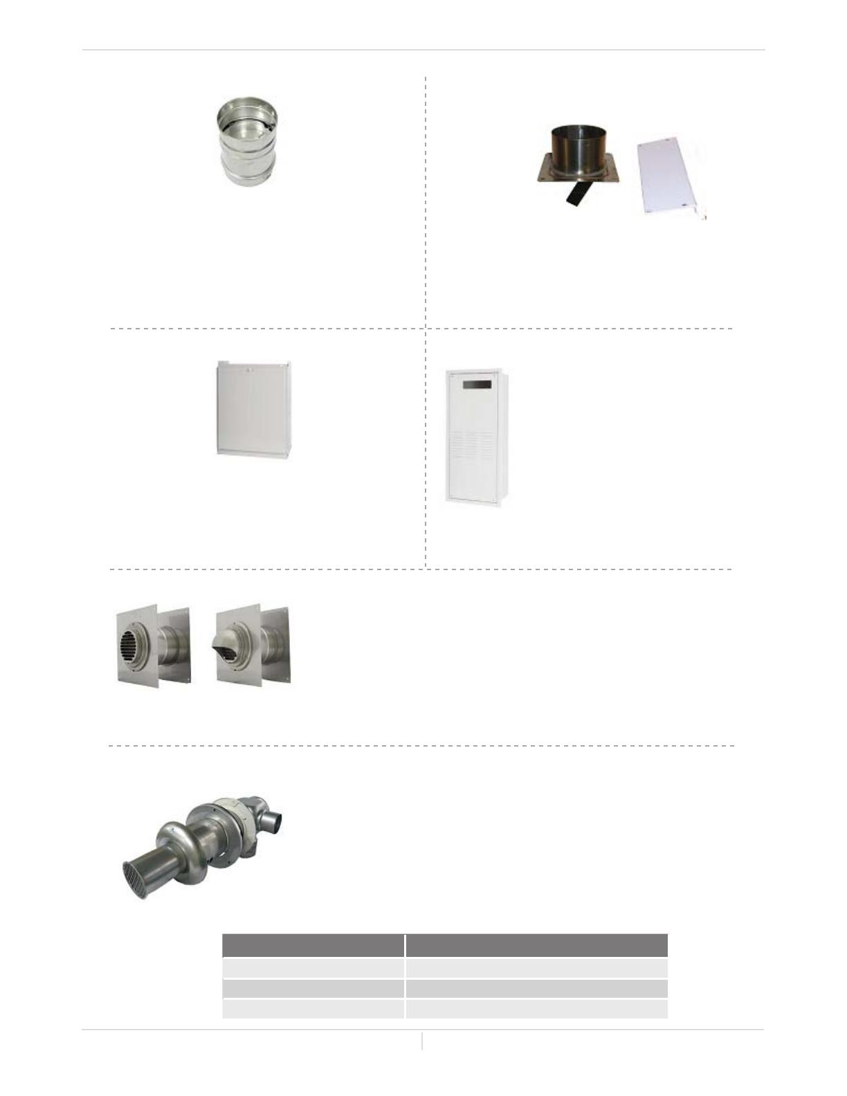
6. Direct-Vent Concentric Termination: 900768005 (TK-KPCT43)
Usedwhenterminatingdirect-vent(sealed-combustion)systems,with
direct-ventmodelsthatrequirea3in.(76mm)intakeanda4in.(102
mm) exhaust. This concentric termination provides the convenience
of only having to make one penetration through a sidewall instead
of two separate penetrationsfor the intake and exhaust piping. The
termination includes a bird screen, restricting small animals, pests,
andforeignobjectsfromenteringintotheventsystem.Thissidewall
terminationisavailableinthreedifferentsizes,tocoverallrangesof
wallthicknesses.
Part# Convering wall thicknesss
9007680005(TK-KPCT43-1) 3.9–7.1in.(99-180mm)
9007772005(TK-KPCT43-2) 6.9–10.1in.(175-257mm)
9007773005(TK-KPCT43-3) 9.8–13.0in.(249-330mm)
4. Recess box: 9007674005 (TK-RB02)
The Recess box will allow for
clean” installations. The water
heater fits inside the recess box,
whichhidesandprotectsthewhole
water heater and plumbing.The
Recessboxwillfitin-betweenmost
wallstuds.
11 Page
WARNING FOR INSTALLATIONS
FOR YOUR SAFETY, READ BEFORE INSTALLATION:
Do not install the heater where water, debris or
flammablevaporsmaygetintotheflueterminal.
Thismaycausedamagetotheheaterandvoidthe
warranty.
Donothavetheventterminalpointingtoward
anyopeningintoabuilding.Donotlocateyour
heaterinapitorlocationwheregasandwater
canaccumulate.
Do not install this water heater under an
overhanglessthan3ft.(914mm)fromitstop
oreaves.Theareaunderanoverhangmustbe
opentothreesides.(Outdoormodelsonly)
Donotinstallthewaterheaterventterminator
within1ft.(305mm)intheUSAofanyairintake
orbuildingopening,andwithin3ft.(914mm)
inCanadaofanyairintakeorbuildingopening.
(Outdoormodelsonly)(Refertop.15)
Do not install next to a dryer or any source
of airborne debris that can be trapped inside
the combustion chamber, unless the system is
directvented.
ProhibitedProhibited
3ft.
(914mm)
1ft.(305mm)USA
3ft.(914mm)Canada
1ft.(305mm)USA
3ft.(914mm)Canada
1ft.(305mm)USA
3ft.(914mm)Canada
12 Page
HIGH-ALTITUDE INSTALLATIONS
Check the elevation where your water heater is installed. Set DIPswitches shown in the table below
dependingonthealtitude.
DIPswitches
110U (T-KJr2U) and 310U (T-K4U) models
Computer board
WARNING
DO NOT adjust any DIPswitches on the upper bank for the 510U (T-D2U)
models.
Installaon
Installaon Manual
NOTE: ThedarksquaresindicatethedirectiontheDIPswitchesshouldbesetto.
DIPswitches(Lowerbank)
510U (T-D2U) models
Computer board
Indoor models
0 (DEFAULT) Up to 2,500 ft Up to 5,000 ft Up to 7,500 ft Over 7,500 ft
110U(T-KJr2U)and
310(T-K4U)models
No.3:OFF
No.4:OFF
No.5:OFF
No.3:OFF
No.4:ON
No.5:OFF
No.3:OFF
No.4:OFF
No.5:ON
No.3:OFF
No.4:ON
No.5:ON
Consultour
Technical
Services
at1-888-
479-8324
510U(T-D2U)models
(Lower bank of
DIPswitches)
No.2:OFF
No.3:OFF
No.4:OFF
No.2:OFF
No.3:ON
No.4:OFF
No.2:OFF
No.3:OFF
No.4:ON
No.2:OFF
No.3:ON
No.4:ON
O F F
O N
1 2 3 4 56 7 8 9 10
O F F
O N
1 2 3 4 56 7 8 9 10
O F F
O N
1 2 3 4 56 7 8 9 10
O F F
O N
1 2 3 4 56 7 8 9 10
O F F
O N
1 2 3 4 56
O F F
O N
1 2 3 4 56
O F F
O N
1 2 3 4 56
O F F
O N
1 2 3 4 56
Altitude
DIPswitches
Outdoor models
0 (DEFAULT) Up to 2,000 ft Up to 4,000 ft Up to 6,000 ft Over 6,000 ft
110U(T-KJr2U)and
310(T-K4U)models
No.3:OFF
No.4:OFF
No.5:OFF
No.3:OFF
No.4:ON
No.5:OFF
No.3:OFF
No.4:OFF
No.5:ON
No.3:ON
No.4:OFF
No.5:ON
Consultour
Technical
Services
at1-888-
479-8324
510U(T-D2U)models
(Lower bank of
DIPswitches)
No.2:OFF
No.3:OFF
No.4:OFF
No.2:OFF
No.3:ON
No.4:OFF
No.2:OFF
No.3:OFF
No.4:ON
No.2:ON
No.3:OFF
No.4:ON
O F F
O N
1 2 3 4 56 7 8 9 10
O F F
O N
1 2 3 4 56 7 8 9 10
O F F
O N
1 2 3 4 56 7 8 9 10
O F F
O N
1 2 3 4 56 7 8 9 10
O F F
O N
1 2 3 4 56
O F F
O N
1 2 3 4 56
O F F
O N
1 2 3 4 56
O F F
O N
1 2 3 4 56
Altitude
DIPswitches
13 Page
VENTING INSTRUCTIONS
For indoor models
-General-
ThewaterheatermustbeventedinaccordancewiththesectionVentingofEquipment"ofthelatest
editionoftheNationalFuelGasCode:ANSIZ223.1/NFPA54intheUnitedStatesand/orSection7ofthe
CAN/CSAB149.1NaturalGasInstallationCodeinCanada,aswellasapplicablelocalbuildingcodes.
The manufacturer recommends the “T-Vent” line manufactured by TAKAGI(RefertoT-Vent”brochure
for details).However,the following are alsoUL listed manufacturers: ProTech Systems Inc. (FasNSeal),
Flex-LInc.,Z-FlexInc.(Z-VentIII),Metal-FabInc.,andHeat-FabInc.(Saf-TVent).
General rules for venting water heaters are:
• Placethewaterheaterascloseaspossibletotheventterminator.
• Theventcollarofthewaterheatermustbefasteneddirectlytoanunobstructedventpipe.
• Donotweldtheventpipetothewaterheatersventcollar.
• Donotcuttheventcollaroftheunit.
• The vent must be easily removable from the top of the water heater for normal service and
inspectionoftheunit.
• Thewaterheaterventmustnotbeconnectedtoanyothergasapplianceorventstack.
• Avoidusinganoversizedventpipeorusingextremelylongrunsofthepipe.
• For rooftop venting, a rain cap or other form of termination that prevents rain water from
enteringintothewaterheatermustbeinstalled.
• Donotcommonventorconnectanyventfromotherappliancestothewaterheatervent.
General rules for vent terminations:
• Avoidlocatingthewaterheaterventterminatornearany air intake devices.Thesefanscanpick
uptheexhaustflueproductsfromthewaterheaterandreturnthemtothebuilding.Thiscan
createahealthhazard.
• Locatetheventterminatorsothatitcannotbeblockedbyanydebris,atanytime.Mostcodes
requirethattheterminatormustbeatleast12in.(305mm)abovegrade,buttheinstallermay
determineifitshouldbehigherdependingonthejobsiteconditionandapplicablecodes.
• A proper sidewall terminator is recommended when the water heater is vented through a
sidewall.
• Regardingtheclearancesfromtheexhaustterminatortotheairinletoropening,refertothe
nextfewpages.
• Improper venting of this appliance can result in excessive levels of carbon
monoxidewhichcanresultinseverepersonalinjuryordeath.
• Improperinstallationcancausenauseaorasphyxiation,severeinjuryordeath
fromcarbonmonoxideandfluegasespoisoning.Improperinstallationwillvoid
productwarranty.
DANGER
Wheninstallingtheventsystem,allapplicablenationalandlocalcodesmustbe
followed.If you install thimbles, fire stops orother protectivedevices andthey
penetrateanycombustibleornoncombustibleconstruction,besuretofollowall
applicablenationalandlocalcodes.
CAUTION
Installaon
Installaon Manual
14 Page
-Vent length and No. of Elbow-
ThisisaCategoryIIIapplianceandmustbeventedaccordingly.Theventsystemmustbesealedairtight.
Allseamsandjointswithout gaskets mustbesealedwithhighheatresistantsiliconesealantorULlisted
aluminumadhesivetapehavingaminimumtemperatureratingof350°F(177°C).Forbestresults,avent
systemshouldbeasshortandstraightaspossible.
• ThiswaterheaterisaCategoryIIIapplianceandmustbeventedaccordinglywithany4in.(102
mm)ventapprovedforusewithCategoryIIIorSpecialBHtypegasvent.
• Follow the vent pipe manufacturers instructions when installing the vent pipe.
• Do not common vent this appliance with any other vented appliance(Donotterminatevent
intoachimney.Iftheventmustgothroughthechimney,theventmustrunallthewaythrough
thechimneywithCategoryIIIapprovedorSpecialBHventpipe).
• Whenthehorizontalventrunexceeds5ft.(1.5m),supporttheventrunat3ft.(0.9m)intervals
withoverheadhangers.
• The maximum length ofexhaustventpiping mustnot exceed50 ft. (15.2 m)(deducting 5ft.
(1.5m)foreachelbowusedintheventingsystem).Donotusemorethan5elbows.
-DIPswitch settings for Direct Vent models-
Diameter Max. No. of Elbow Max. Vertical and Horizontal (Total) Vent Length
4in.(102mm) 5 50ft.(15.2m)
*For each elbow added, deduct 1.5m (5 ft.) from max. vent length.
Installaon
Installaon Manual
No. of Elbows Max. Vertical or Horizontal Vent Length
0 50ft.(15.2m)
1 45ft.(13.7m)
2 40ft.(12.2m)
5 25ft.(7.6m)
Excludeselbowtermination,raincaps,orthe4in.(102mm)PVCConcentricTermination
SetDIPswitchesshowninthetablebelowdependingontheventlength.
110U Direct vent (T-KJr2U-IN)
310 Direct vent (T-K4U-IN)
510U Direct vent (T-D2U-IN)
(Upper bank of DIPswitches)
Vent length
No.6:ON
No.7:OFF
No.3:ON
No.4:OFF
0 to 30 ft
No.6:ON
No.7:ON
No.3:ON
No.4:ON
31 to 50 ft
O F F
O N
1 2 3 4 56 7 8
O F F
O N
1 2 3 4 56 7 8
O F F
O N
1 2 3 4 56 7 8 9 1 0
O F F
O N
1 2 3 4 56 7 8 9 1 0
15 Page
-Venng Illustraons-
For the 110U Indoor (T-KJr2U-IN), 310U Indoor (T-K4U-IN) and 510U Indoor (T-D2U-IN) models
Fordetailsoftheoptionalitems,refertotheInstallationmanualforeachOptionalitem.
Horizontal Installaon Diagram With
Direct-Vent Concentric Terminaon
Wall
Direct-vent
Concentric
Terminaon
Installaon Diagram of Direct-Vent
Conversion Kit with water heater
Thewaterheater
IntakeportofDirect-Vent
ConversionKit
(FordetailsseeP.10)
*BackflowPreventer(Recommendedforfreezingweatherconditions:36°F(2°C)andbelow).
**VerticalCondensationDrainmustbeinstalledinaccordancewithlocalcodes.
Installaon
Installaon Manual
PlateofDirect-VentConversionKit
Horizontal Installaon Diagram
Wall
SidewallVent
Terminator
VerticalCondensationDrain**
Backflow
Preventer*
Vercal Installaon Diagram
Backflow
Preventer*
RainCap
Roof
VerticalCondensationDrain**
RoofFlashing
Vercal Installaon Diagram
(With direct-venng)
Horizontal Installaon Diagram
(With direct-venng)
Roof
SidewallVent
Terminator
VercalCondensaonDrain**
Backow
Preventer*
Seethepicturebelowfordetailedconnecon
instruconstoDirect-VentConversionKit.
Backow
Preventer*
Firestop
VercalCondensaon
Drain**
Wall
Roof
Flashing
RainCap
16 Page
-Vent terminaon clearances-
Canada U.S.A
Directventandother
thanDirectVent
Direct
vent
Otherthan
DirectVent
A
Clearanceabovegrade,veranda,porch,deck,or
balcony.
1foot 1foot 1foot
B Clearancetowindowordoorthatmaybeopened 3feet 1foot
4feetfrombelowor
sideopening.1foot
fromaboveopening.
C Clearancetopermanentlyclosedwindow * * *
D
Verticalclearancetoventilatedsoffitlocatedabove
theventterminatorwithinahorizontaldistance
of2feet(61cm)fromthecenterlineofthe
terminator.
* * *
E Clearancetounventilatedsoffit * * *
F Clearancetooutsidecorner * * *
G Clearancetoinsidecorner * * *
H
Clearancetoeachsideofcenterlineextended
abovemeter/regulatorassembly
3feet * *
I Clearancetoserviceregulatorventoutlet. 3feet * *
J
Clearancetonon-mechanicalairsupplyinletto
buildingorthecombustionairinlettoanyother
application
3feet 1foot
4feetfrombelowor
sideopening.1foot
fromaboveopening.
K Clearancetomechanicalairsupplyinlet. 6feet 3feet 3feet
L
Clearanceabovepavedsidewalkorpaveddriveway
locatedonpublicproperty.
7feet * 7feet
M Clearanceunderveranda,porchdeck,orbalcony. 1foot * *
*ForclearancesnotspecifiedinANSIZ223.1/NFPA54orCAN/CSA-B149.1,pleaseuseclearancesinaccordance
withlocalinstallationcodesandtherequirementsofthegassupplier.
Installaon
Installaon Manual
INSIDECORNERDETAIL
V
Gasmeter/regulator
V
V
V
V
V
V
V
V
V
X
X
X
Ventterminal
Airsupplyinlet
Areawhereisnotpermitted
G
A
E
D
B
L
C
F
B
B
B
B
A
J
OPERABLE
FIXED
CLOSED
B
H
M
K
OPERABLE
FIXED
CLOSED
I
17 Page
-For sidewall terminaons-
For multiple sidewall exhaust terminations (e.g. multi-
unit systems),an exhaust terminationmust be at least1
ft. (305mm) away from another exhaust termination. An
exhaust termination mustalso be atleast2 ft.(610 mm)
awayfromaninsidecorner(iftheadjacentwallislessthan
2ft.(610mm) of length,theminimumrequired distance
awayfromtheinsidecornerwillbeequaltothelengthof
thatadjacentwall).
For multiple-unit, direct-vent sidewall terminations that
combinetheintakeandexhaustintoasinglepenetration,
spaceeachdirect-ventterminationatleast1ft.(305mm)
awayfromeachother,nomattertheorientation.Adirect-
ventterminationmustalsobeatleast2ft.(610mm)away
fromaninsidecorner(iftheadjacentwallislessthan2ft.
(610mm)oflength,theminimumrequireddistanceaway
fromtheinsidecornerwillbeequaltothelengthofthat
adjacentwall).
For direct-vent sidewall
terminationsthatusetwo
separatepenetrationsfor
the intake and exhaust,
distance the intake and
exhaust terminations at
least3ft.(915mm)away
from each other, no
mattertheorientation.
For multiple-unit rooftop terminations (whether for standard or direct-vent installations) space all
exhaustandintaketerminationsinaccordancewithlocalcodes.Anexhaustterminationmustbespaced
fromawallorsurfaceinaccordancewithlocalcodesaswell.Intheabsenceofsuchacode,anexhaust
terminationmustbeahorizontaldistanceofatleast2ft.(610mm)awayfromawallorsurface.
Exhaust and/or
direct-vent sidewall
terminations should
be at least 2 ft. (610
mm) away from an
opposite surface/
wall.Donotplacethe
termination directly
infrontofanopening
intoabuilding
.
 2ft.
(610mm)
Exhaust
termination
Please follow all local and national codes in regards to proper termination
clearances.Intheabsenceofsuchcodes,thefollowingclearancescanbeusedas
guidelines.Localcodessupersedetheseguidelines.
CAUTION
Installaon
Exhaust
termination
Inside
corner
1ft.
(305mm)
2ft.
(610mm)
1ft.
(305mm)
Combined
intakeand
exhaust
termination
Inside
corner
1ft.
(305mm)
2ft.
(610mm)
1ft.
(305mm)
Installaon Manual
-For rooop terminaons-
A:Inaccordancewithlocalcodes
Airintake
A
Exhaustterminaon
A
A
A
A
Air intake
2.
(610mm)
Exhaust
terminaon
3ft.
(915
mm)
Airsupplyinlet
3ft.
(915mm)
3ft.
(915mm)
Exhaust
termination
18 Page
GAS SUPPLY AND GAS PIPE SIZING
-General-
• Theminimumandmaximuminletgaspressuresare:
• Gas pressure above this specified range for the water heater and/or insufficient gas volume will
adverselyaffectperformance.Thesepressuresaremeasuredwhenthewaterheaterisinfulloperation.
• Inletgaspressuremustnotexceedtheabovemaximumvalues;gaspressureabovethespecifiedrange
willcausedangerousoperatingconditionsanddamagetotheunit.
• Untiltestingofthemaingaslinesupplypressureiscompleted,ensurethegaslinetothewaterheater
isdisconnectedtoavoidanydamagetothewaterheater.
-Gas connecons-
1. Installamanualgasshut-offvalvebetweenthewaterheaterandthegassupplyline.
2. Whenthegasconnectionsarecompleted,itisnecessarytoperformagasleaktest(seebelow)either
byapplyingsoapywatertoallgasfittingsandobservingforbubblesorbyusingagasleakdetection
device.
• Thewaterheateranditsindividualshutoffvalvemustbedisconnectedfromthegassupply
pipingsystemduringanypressuretestingofthatsystemattestpressuresinexcessof1/2psi
(3.5kPa).
• Thewaterheatermustbeisolatedfromthegassupplypipingsystembyclosingitsindividual
manualshutoffvalveduringanypressuretestingofthegassupplypipingsystemattest
pressuresequaltoorlessthan1/2psi(3.5kPa).
3. Alwayspurgethegaslineofanydebrisand/orwaterbeforeconnectingtothegasinlet.
Sizethegaspipeappropriatelytosupplythenecessaryvolumeofgasrequired
forthewaterheaterusingANSI233.1/NFPA54intheUSAorCAN/CSAB149.1in
Canadaorlocalcodes.Otherwise,flowcapabilitiesandoutputtemperatureswill
belimited.
NOTICE
Gas type Inlet gas pressure
NaturalGas Min.5.0”W.C . (1.24kPa)–Max.10.5”W.C . (2.61kPa)
• Check that the type of gas matches the rating plate first.
• Ensure that any and all gas regulators used are operating properly and
providing gas pressures within the specified range shown below. Excess gas
inlet pressure may cause serious accidents.
• Conversion of this unit from natural gas or vise versa will void all warranty.
Contact your local distributor to get the correct unit for your gas type. The
manufacturer is not liable for any property and/or personal damage resulting
from gas conversions.
CAUTION
Installaon
Installaon Manual
19 Page
-Natural Gas Supply Piping-
MaximumdeliveryCapacityofCubicFeetofGasperHourofIPSPipecarryingNaturalGaswith0.60SpecificGravity
BasedonPressureDropof0.5"W.C.
Based on Energy Content of 1,000 BTU/Cubic ft.: The water heater requires 140 Cubic ft./hr for the 110U (T-KJr2U)
models, 190 Cubic ft./hr for the 310U (T-K4U) models, and 199 Cubic ft./hr for the 510U (T-D2U) models.
Pipe Size Length
Diameter 10' 20' 30' 40' 50' 60' 70' 80' 90' 100' 125' 150' 200'
3/4"
363 249 200 171 152 138 127 118 111 104 93 84 72
1" 684 470 377 323 286 259 239 222 208 197 174 158 135
1
1/4"
1,404 965 775 663 588 532 490 456 428 404 358 324 278
1
1/2"
2,103 1,445 1,161 993 880 798 734 683 641 605 536 486 416
2" 4,050 2,784 2,235 1,913 1,696 1,536 1,413 1,315 1,234 1,165 1,033 936 801
Unit: Cubic Feet per Hour
BasedonEnergyContentof1,000BTU/Cubicft:
Divideeachappliance'sBTUrequirementby1,000BTU/htogettheappliancesCubicFt.requirement.
Takeintoaccountthedistancetheapplianceisfromthegasmeter,lookintheabovegascharttoproperly
sizetheline.
Forsectionsofthegaslinesupplyinggastomorethanoneappliance(Ex:PointAtoPointB),addupthecubic
ft.requirementsoftheappliancesthatarebeingsuppliedbythatsection,andsizetothefarthestappliance.
For Example: The section from A to B supplies gas to the furnace, range and dryer. Adding up the BTU
requirementsanddividingby1,000yieldsacubicft.requirementof220cubicft.ofgas.Thefarthestappliance
istherange,whichis50ft.awayfromthemeter.Lookingattheabovechart,andunderthecolumnof50ft.,
SectionAtoBneedstobe1"inordertosupply220cubicft.
Installaon
Installaon Manual
Water
Heater
199,000BTU/h
Dryer
35,000BTU/h
Gas Meter
Furnace
120,000BTU/h
Range
65,000BTU/h
A
B
C
10'Length
1/2"PipeSize
15'Length
1/2"PipeSize
15'Length
1"PipeSize
10'Length
3/4"PipeSize
10'Length
1"PipeSize
5'Length
1-1/4"PipeSize
10'Length
3/4" Pipe Size
5'Length
1-1/4"PipeSize
Gas Sizing Example
(Natural Gas)
20 Page
-Measuring inlet gas pressure-
Thewaterheatercannotperformproperlywithoutsufficientinletgaspressure.Belowareinstructionson
howtochecktheinletgaspressure.THIS IS ONLY TO BE DONE BY A LICENSED PROFESSIONAL.
WATER CONNECTIONS
Allpipes,pipefittings,valvesandothercomponents,includingsolderingmaterials,mustbesuitablefor
potablewatersystems.
1.Amanualshutoffvalvemustbeinstalledonthecoldwaterinlettothewaterheaterbetweenthemain
watersupplylineandthewaterheater.
2. Inaddition,amanualshutoffvalveisalsorecommendedonthehotwateroutletoftheunit.Ifthe
waterheaterisinstalledwithin,orsubjectedto,aclosedloopwatersystem,athermalexpansiontank
mustbeinstalled.
1. Turnoffallelectricpowertothewaterheaterifserviceistobeperformed.
2. Turnthemanualgasvalvelocatedontheoutsideoftheunitclockwisetothe
offposition.
• Do not use this water heater if any part has been submersed under water.
Immediatelycallalicensedprofessionaltoinspectthewaterheatertoreplace
anydamagedparts.
• Do not reversethe hotoutlet andcold inletconnections to thewater heater.
Thiswillnotproperlyactivatethewaterheater.
CAUTION
Installaon
Installaon Manual
1. Shutoffthemanualgasvalveonthesupplygasline.
2. Removethe screwfor the pressure port located onthe
gasinletofthewaterheatershowninthediagramright.
3. Connectthemanometertothepressureport.
4. Re-open the manual gas valve. Check to see thatthere
arenogasleaks.Opensomeofthefixturesthatusethe
highestflowratetoturnonthewaterheater.
5. Checkthe inlet gas pressure. When the water heater is
onmaximumandminimumburn,themanometershould
readfrom5.0”to10.5”W.C.(1.24to2.61kPa)forNatural
gas.
3. Beforeinstallingthewaterheater,flush
thewaterlinetoremovealldebris,and
after installation is complete, purge
theairfromtheline. Failuretodoso
maycausedamagetotheheater.
4. There is a wire mesh filter within
the cold inlet to trap debris from
entering your heater. This will need
tobecleanedperiodicallytomaintain
optimumflow.(RefertoP.36)
Pressureport
Cold
inlet
Hot
outlet
Gas
inlet
As Close as
Possible
Pressure Relief Valve
  • Page 1 1
  • Page 2 2
  • Page 3 3
  • Page 4 4
  • Page 5 5
  • Page 6 6
  • Page 7 7
  • Page 8 8
  • Page 9 9
  • Page 10 10
  • Page 11 11
  • Page 12 12
  • Page 13 13
  • Page 14 14
  • Page 15 15
  • Page 16 16
  • Page 17 17
  • Page 18 18
  • Page 19 19
  • Page 20 20
  • Page 21 21
  • Page 22 22
  • Page 23 23
  • Page 24 24
  • Page 25 25
  • Page 26 26
  • Page 27 27
  • Page 28 28
  • Page 29 29
  • Page 30 30
  • Page 31 31
  • Page 32 32
  • Page 33 33
  • Page 34 34
  • Page 35 35
  • Page 36 36
  • Page 37 37
  • Page 38 38
  • Page 39 39
  • Page 40 40
  • Page 41 41
  • Page 42 42
  • Page 43 43
  • Page 44 44
  • Page 45 45
  • Page 46 46
  • Page 47 47
  • Page 48 48
  • Page 49 49
  • Page 50 50
  • Page 51 51
  • Page 52 52
  • Page 53 53
  • Page 54 54
  • Page 55 55
  • Page 56 56

A.O. Smith ATI-310U-N Technical Documents

Category
Water heaters & boilers
Type
Technical Documents

Ask a question and I''ll find the answer in the document

Finding information in a document is now easier with AI