Page is loading ...

IN WALL PRESSURE BALANCING
BATH AND SHOWER SETS
To assure proper positioning in relation to wall,
note roughing-in dimensions.
ROUGHING-IN DIMENSIONS
Certified to comply with ANSI A112.18.1
Installation
Instructions
ARIANA
6021
6022
THREADED INLETS (STOPS)
INLETS
1/2" NPT
5-7/8"
OUTLETS
1/2" NPT
3-3/8"
INLETS 1/2" NPT
OUTLETS
1/2" NPT
3-3/8"
3-3/8"
THREADED INLETS
FINISHED WALL
4"
BOTTOM OF TUB
74" FOR HEAD
CLEARANCE
5-1/8" REF.
7-7/8" REF.
18" OPTIONAL
1/2" NPT
5" REF.
1/2" NPT
1-5/8"
to
3-1/4"
SLIP-ON
SPOUT
7-1/8"
4-1/8"
REF.
OPTIONAL TO FINISHED
FLOOR USUALLY
BETWEEN 65'' AND 80''
TOP OF TUB RIM
Off
H
o
t
Tubing Cutter
4mm (5/32")
Hex Wrench
M968457 REV.1.3
Recommended Tools
Adjustable Wrench
Channel Locks
Flat Blade Screwdriver
Plumbers' Putty or Caulking
Phillips Screwdriver
Thank you for selecting American-Standard...the benchmark
of fine quality for over 100 years.
To ensure that your installation proceeds smoothly--please
read these instructions carefully before you begin.

See Roughing-in diagram before starting.
Connections are:
1/2" female NPT for threaded inlets
Connect RISER PIPE (1) to MANIFOLD (2) top outlet marked "SHR".
Connect TUB FILLER PIPE (3) at bottom outlet marked "TUB".
For proper positioning the finished wall must be within side wall of PLASTER GUARD (4).
If the valve is installed on a fiberglass or other thin wall application, the PLASTER GUARD (4) can be used
as a support.
Cut a 3" dia. hole in the shower stall.
Drill two additional 1" holes to allow access to the stops.
Remove PLASTER GUARD (4), rotate 90˚ so that indicated screw holes fit MANIFOLD (2).
Push CAP on valve, place ESCUTCHEON on and attach with screws.
Connect hot and cold water supplies.
Cap off shower pipe (5) and tub filler pipe (6).
For support, use pipe BRACES (7) secured to wooden braces.
With valve turned off, turn on water supplies. Check for leaks.
1
ROUGHING-IN
Turn off water at main supply.
CAUTION
When soldering, remove PLASTER GUARD, CARTRIDGES and CHECK STOPS (IF PRESENT). When finished soldering,
flush valve body, replace cartridges, check stops (if present) and plaster guard to continue installation. Use thread
sealant or Teflon tape on threaded connections.
NOTE
COLD
HOT
1
7
5
3
6
4
2
M968457 REV.1.3

A
6
7
3
1
4
5
2
8
SHOWER ARM
FLANGE
SPOUT FLANGE
Off
H
ot
4-1/8"
REF.
M968457 REV.1.3
2
INSTALL TRIM
CAUTION: Protect finish on SHOWER ARM, SHOWER HEAD and TUB SPOUT when installing.
When finished tiling the wall, remove PLASTER GUARD (A)
and turn off water supply.
Push CAP (1) over VALVE CARTRIDGE (2).
Push CAP (3) over VALVE CARTRIDGE (4).
Mount ESCUTCHEON (3) and gasket to valve body with SCREWS (4).
Remove PIPE CAP (5) from shower pipe. Use sealant on both ends of SHOWER ARM (6) and thread long end into
shower elbow. Thread SHOWER HEAD (7) to SHOWER ARM (6).
Install TUB FILLER SPOUT (8) with flange flush against finished wall.

ADJUST HOT LIMIT STOP
By restricting HANDLE rotation and limiting the amount of hot
water allowed to mix with the cold, the HOT LIMIT SAFETY
STOP (1) reduces risk of accidental scalding. To set the maximum
hot water temperature of your faucet, all you need to do
is adjust the setting on the HOT LIMIT SAFETY STOP (1).
4
Turn CARTRIDGE STEM (2) to the OFF position (coldest setting)
before making adjustment to HOT LIMIT STOP (1). Use a
flat blade screwdriver to pry free the HOT LIMIT SAFETY STOP (1).
Pull forward and rotate counterclockwise one number to limit hot
water temperature. Use ARROW (3) on CARTRIDGE (4) and
NUMBERS (5) on HOT LIMIT STOP (1) for indication.
1
5
1
3
1
1
9
7
5
3
1
0
1
5
1
3
1
1
9
7
5
3
1
1
5
1
3
1
1
9
7
5
3
1
COLDER
(Larger Numbers)
0 1 3 5 7 9 11 13 15
HOTTER
(Smaller Numbers)
0 1 3 5 7 9 11 13 15
1
5
5
4
4
3
3
2
2
3
INSTALL HANDLE
Find correct position of HANDLE (1) and push
HANDLE (1) onto VALVE STEM (4).
Install HANDLE SCREW (2) and push in INDEX
CAP (3).
Check proper operation of HANDLE (1).
Turn on water supply on and test installed fitting.
Operate valve and diverter spout.
1
1
2
3
4
Off
Hot
M968457 REV.1.3

5
Pull INDEX CAP, unscrew HANDLE SCREW and pull HANDLE off valve stem.
Remove two SCREWS holding ESCUTCHEON and remove ESCUTCHEON.
Remove COVER by pulling straight out.
Shut off water supply by either closing off main water supply, or closing off the hot and cold CHECK STOPS on valve.
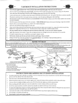
TO GAIN ACCESS TO VALVE FOR SERVICING
Remove CARTRIDGE (1) by removing CARTRIDGE SCREWS (2). Remove three SCREWS (3) from FIXATION RING (4) and
pull out PRESSURE BALANCING (5) unit.
Clean SEALS (9) on base of CARTRIDGE (1). Check base of PRESSURE BALANCING UNIT (5) and clean O-RINGS (6). Remove
CAPS (7) and check O-RINGS on inside of CAPS (7). Clean inside sealing surfaces of VALVE BODY (8).
Re-assemble PRESSURE BALANCING UNIT (5) and CARTRIDGE (1). Tighten all screws.
Turn on water supply and see above for installing TRIM and HANDLE.
VALVE LEAKS WHEN SHUT OFF
BACK TO BACK INSTALLATION
Remove PRESSURE BALANCE UNIT (5).
Remove CAPS (7) and clean valve thoroughly.
Examine balancing unit and check condition of O-ring on end of piston. Piston should move back and forth. Order Repair
Part M952100-0070A if balancing unit is defective.
Replace CAPS (7) and install PRESSURE BALANCE UNIT (5). Make sure inlets line up with two holes in bottom of casting.
Top flange should butt-up against top of casting.
Remove PRESSURE BALANCE UNIT (5). Rotate PRESSURE BALANCE UNIT (5) 180˚ so that the inlets face up and the
large outlet port faces down.
Push PRESSURE BALANCE UNIT (5) in casting make sure inlets line up with holes in bottom of casting. Top flange should
butt up against top of casting.
Reassemble FIXATION RING (4) and CARTRIDGE (1).
UNABLE TO MAINTAIN CONSTANT TEMPERATURE
BACK TO BACK INSTALLATION
ROTATE 180˚
1
2
9
5
5
7
8
6
4
3
INLETS
LARGE OUTLET
6
M968457 REV.1.3
DO: SIMPLY RINSE THE PRODUCT CLEAN WITH CLEAR WATER. DRY WITH A SOFT COTTON FLANNEL CLOTH.
DO NOT: DO NOT CLEAN THE PRODUCT WITH SOAPS, ACID, POLISH, ABRASIVES, HARSH CLEANERS, OR A
CLOTH WITH A COARSE SURFACE.
CARE INSTRUCTIONS:

M953564-0020A
M953564-2750A
M953564-2950A
SHOWER HEAD
A954440-0070A
CARTRIDGE
023603-0070A
CARTRIDGE SCREWS
A923611-0070A
HOT LIMIT STOP
M961854-0070A
FIXATION RING WITH SCREWS
M952100-0070A
PRESSURE BALANCING UNIT
M962286-0020A
M962286-2750A
M962286-2950A
SHOWER ARM AND ESCUTCHEON
WITH SEALS
M907051-0020A
M907051-2750A
M907051-2950A
CARTRIDGE CAP
078016-0020A
078016-2750A
078016-2950A
ESCUTCHEON SCREWS
M962293-0020A
M962293-2750A
M962293-2950A
ESCUTCHEON KIT
WITH SCREWS
1
5
1
3
1
1
9
7
5
3
1
MODEL NUMBER
027816-0070A
1/2" NPT PLUG
Appropriate finish code
ARIANA
PRESSURE BALANCING
BATH AND SHOWER SETS
M909732-0020A
M909732-2750A
M909732-2950A
SPOUT ESCUTCHEON
M950225-0020A
M950225-2750A
M950225-2950A
DIVERTER SPOUT
A918657-0070A
HANDLE SCREW
M916529-0020A
M916529-2750A
M916529-2950A
LEVER HANDLE
M907024-0022A
M907024-2752A
M907024-2952A
INDEX BUTTON (ARROW)
6021
6022
Off
H
ot
CHROME 002
BRUSHED BRASS 275
SATIN NICKEL 295
M968457 REV.1.3
For toll-free information and answers to your questions, call:
1-800 442-1902
Weekdays 8:00 a.m. to 6:00 p.m. EST
IN CANADA 1-800-387-0369 (TORONTO 1-905-306-1093)
Weekdays 8:00 a.m. to 7:00 p.m. EST
IN MEXICO 01-800-839-12-00
Product names listed herein are trademarks of American Standard Inc.
© AS America, Inc. 2008
HOT LINE FOR HELP
/