Quantum EK User guide
- Category
- Computer liquid cooling
- Type
- User guide
This manual is also suitable for

USER GUIDE
DISTRIBUTION PLATE
EKQuantum
Reflection2 PC-O11D EVO D5 PWM D-RGB

Please note the installation of the product is intended to be
undertaken by an adequately trained and experienced person.
You are installing the product at your own risk. If you are not
properly trained or experienced or feel unsure about the
installation procedure, please refrain from installing the product
yourself and contact our tech support for assistance. We disclaim
our liability for any damages to the product as well as incidental,
consequential, or indirect damages incurred due to improper or
inappropriate installation
Before you start using this product please follow these basic guidelines:
Please carefully read the manual before beginning with the
installation process!
The EK Fittings require only a small amount of force to screw
them firmly in place since the liquid seal is ensured by the
rubber O-ring gaskets.
The use of corrosion inhibiting coolants is always recommended
for any liquid cooling system. EKWB recommends any of the
EKCryofuel for worry-free usage.

- 3 -
TABLE OF CONTENT
BOX CONTENTS 4
DISTRIBUTION PLATE DIMENSIONS 5
TECHNICAL SPECIFICATIONS AND PRODUCT PARTS 6
PREPARING THE 011D EVO CHASSIS 7
PREPARING AND INSTALLING THE DISTRIBUTION PLATE 8
RECOMMENDED DISTRIBUTION PLATE CONFIGURATIONS 9
ATTACHING THE PUSH-IN ADAPTER (OPTIONAL) 11
FLOW DIAGRAM 12
CONNECTING THE D-RGB LED STRIP 13
CONNECTING THE PUMP 13
TESTING THE LOOP 14
SUPPORT AND SERVICE 15
SOCIAL MEDIA 15

- 4 -
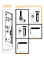
BOX CONTENTS
EK-Quantum Reflection2 PC-O11D
EVO D5 PWM D-RGB
Screw M4x8 DIN7991 (2 pcs)
Screw M3x8 DIN7991 (2 pcs) Allen Key 2.5 mm (1 pc)
Allen Key 2 mm (1 pc)
EK-Loop Multi Allen Key (1 pc)
Mounting Mechanism EAN: 105504

- 5 -
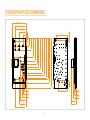
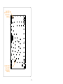
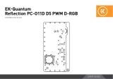
DISTRIBUTION PLATE DIMENSIONS
45.1 mm
101.1 mm
161.2 mm
170.4 mm
207.3 mm
26 mm
65 mm
94.3 mm
157.8 mm
71 mm
71 mm
185.8 mm
213.8 mm
234.1 mm
254.4 mm
283.8 mm
304.1 mm
324.2 mm
336 mm
405.2 mm
361.2 mm
29 mm
44 mm
57 mm
85 mm
100 mm
170.4 mm
171.9 mm
19 mm
62 mm
137.4 mm 8 mm
25.6 mm
41.6 mm
71.4 mm
75.4 mm

- 6 -
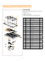
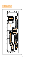
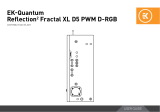
TECHNICAL SPECIFICATIONS AND PRODUCT PARTS
6
16
12
3
11
18
17
1
4
19
2
13
20
9
Technical Specification:
Dimensions with the attached pump (W x D x H): 207.3 x 75.4 x 405.2 mm
– D-RGB LED count: 21
– D-RGB cable length: 500 mm
– D-RGB connector standard 3-pin (+5V, Data, Blocked, Ground)
Position EAN Description Quantity
1104705 TOP Plexi (Block part) 1
2104706 TOP Plexi (Lid part) 1
33831109837597 EK D5 Pump 1
4101803 Pump holder 1
5104709
LED Cover (Black e.)
1
6100663 EK - Badge 2
78206
Screw M4 x 12 DIN7991
65
88204
Screw M3 x 20 DIN7991
4
99017
Screw M4 x 20 DIN7984
4
10 104599 Mylar sticker 2
11 5154 OR - 52 x 3 NBR50 1
12 104716 OR - 397 x 2 mm 1
13 104717 OR - 57 x 2 mm 1
14 104718 OR - 113 x 2 mm 1
15 104719 OR - 94 x 2 mm 1
16 104720 OR - 102 x 2 mm 1
17 104721 OR - 128 x 2 mm 1
18 104722 OR - 108 x 2 mm 1
19 3831109895313 Push-in adapter 4
20 102639 EK - Plug G1/4 13
21 3831109834282
Plug cover (Acetal)
13
22 102458
LED D-RGB strip 800/600 mm
1
8
14
5
22
21
10
15
7

- 7 -
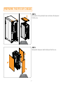
PREPARING THE 011D EVO CHASSIS
STEP 1
Unscrew the factory provided screws and remove the top panels
from the case.
STEP 2
STEP 2
Remove both side panels and the front panel from the case.
STEP 1

- 8 -
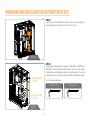
STEP 2
Secure the distribution plate using the included M3 x 8 and M4 x 8
DIN7991 screws through the front frame of the case. The screws
shouldn’t be over-tightened to avoid cracking the plexi. The screw
heads should sink in as not to interfere with the mounted front panel.
STEP 2
PREPARING AND INSTALLING THE DISTRIBUTION PLATE
STEP 1
Carefully place the distribution plate into the case and align the
mounting holes. Be careful not to scratch the acrylic!
STEP 1
M3 x 8 DIN7991
SCREW
M4 x 8 DIN7991
SCREW
For this step you will need:
Allen Key 2 mm Allen Key 2.5 mm

- 9 -
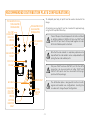
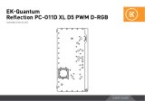
RECOMMENDED DISTRIBUTION PLATE CONFIGURATIONS
SIDE RADIATOR
INLET
TOP RADIATOR
INLET
BOTTOM
RADIATOR
OUTLET
SIDE RADIATOR
OUTLET
CPU OUTLET
CPU INLET
TOP RADIATOR OUTLET
(TRIPLE RADIATOR
CONFIGURATION) TOP RADIATOR OUTLET
(DUAL RADIATOR
CONFIGURATION)
GPU INLET
GPU OUTLET
BOTTOM
RADIATOR
INLET
DRAIN PORT
(FILL PORT
IN FLIPPED
CONFIG)
FILL PORT
(DRAIN PORT
IN FLIPPED
CONFIG)
To complete your loop, all ports must be used as marked in the
image.
All remaining unused ports must be closed with supplied plugs,
using the EK-Loop Multi Allen Key.
If one of the prescribed components will not be installed
(ie. bottom radiator or GPU block) then one INLET and
one OUTLET port must still be joined together in order
for this distribution plate to function!
Note that the side radiator is completely optional and a
loop without the side radiator can be completed without
joining the two side radiator ports.
Only one INLET and one OUTLET port for the GPU
connection can be used, while all other INLET and
OUTLET GPU ports must be closed with G1/4 plugs
(enclosed in the package).
The distribution plate is designed to function in both
regular and inverted case configurations. Inverting the
case does not change the port configuration.

- 10 -
DRAIN PORT
(FILL PORT
IN FLIPPED
CONFIG)
FILL PORT
(DRAIN PORT
IN FLIPPED
CONFIG)

- 11 -
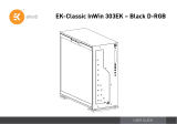
ATTACHING THE PUSH-IN ADAPTER (OPTIONAL)
The push-in adapters can be attached to the marked places in the
diagram.
For easier installation of the push-in adapters, EK recommends to
lubricate the O-rings with a few drops of coolant or water.
OPTIONAL
PUSH-IN
ADAPTER
HOLES

- 12 -
FLOW DIAGRAM

- 13 -
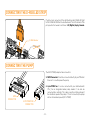
CONNECTING THE D-RGB LED STRIP
Plug the 3-pin connector of the distribution plate D-RGB LED light
to the D-RGB HEADER on the motherboard. The LED will work if the
pin layout on the header is as follows: +5V, Digital, Empty, Ground.
D-RGB Header
RGB Header
CONNECTING THE PUMP
The EK-D5 PWM pump has two connectors.
1. SATA Connector: It must be connected directly to your PSU at all
times as it is used to power the pump.
2. 4-pin PWM fan: It can be connected to your motherboard’s
CPU_ Fan or designated water pump header. It can also be
connected to a controller. This cable is used to control and report
the rotational speed of the pump. If it’s not connected, the pump
will run at maximum speed (100% PWM).
SATA
CONNECTOR 4-PIN PWM FAN
CONNECTOR

- 14 -
To make sure the installation of EK components was successful, we
recommend you perform a leak test for 24 hours.
When your loop is complete and filled with coolant, connect the
pump to a PSU outside of your system. Do not connect power to
any of the other components. Turn on the PSU and let the pump
run continuously. It is normal for the coolant level to drop during this
process as air collects in the distribution plate.
Inspect all parts of the loop, and in the eventuality that coolant leaks,
fix the issue and repeat the testing process. Ensure that all hardware is
dry before the system is powered on in order to prevent any damage.
TESTING THE LOOP

In case you need assistance or wish to order spare parts or a new
mounting mechanism, please contact:
https://www.ekwb.com/customer-support/
For spare parts orders, refer to the page with “TECHNICAL
SPECIFICATIONS AND PRODUCT PARTS” where you can find the
EAN number of each part you might need.
Include the EAN number with quantity in your request. Mounting
Mechanism EAN can be found under “BOX CONTENTS”
Thermal pads are readily available in the EK shop
EKWaterBlocks
@EKWaterBlocks
ekwaterblocks
ekwaterblocks
EKWBofficial
SUPPORT AND SERVICE
SOCIAL MEDIA
-
 1
1
-
 2
2
-
 3
3
-
 4
4
-
 5
5
-
 6
6
-
 7
7
-
 8
8
-
 9
9
-
 10
10
-
 11
11
-
 12
12
-
 13
13
-
 14
14
-
 15
15


Quantum EK User guide
- Category
- Computer liquid cooling
- Type
- User guide
- This manual is also suitable for
Ask a question and I''ll find the answer in the document
Finding information in a document is now easier with AI
Other documents
-
 ekwb EK-Quantum Reflection² ROG Hyperion D5 PWM D-RGB Installation guide
-
 ekwb EK-Quantum Reflection PC-O11D D5 PWM D-RGB Installation guide
-
 ekwb EK-Quantum Reflection² Fractal XL D5 PWM D-RGB Installation guide
-
ekwb EK-Quantum Scalar Flow Indicator Bottom-To-Top D-RGB Installation guide
-
ekwb Reflection2 User guide
-
-
 ekwb EK-Quantum Scalar Flow Indicator Bottom-To-Top D-RGB – Nickel Installation guide
-
-
 ekwb EK-Quantum Reflection PC-O11D XL D5 PWM D-RGB Installation guide
-
 ekwb EK-Classic InWin 303EK Installation guide


