- 6 -
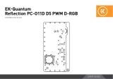
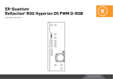
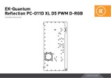
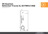
TECHNICAL SPECIFICATIONS AND PRODUCT PARTS
11
10
27
16
2
1
20
23
24
14
5
3
17
25
15
13
8
12
9
6
4
19
18
26
22 21
7
Technical Specification:
Dimensions with the attached pump (W x D x H): 215.1 x 77.8 x 471.9 mm
– D-RGB LED count:
– D-RGB cable length: 500 mm
– D-RGB connector standard 3-pin (+5V, Data, Blocked, Ground)
Position EAN Description Quantity
1104634 TOP Plexi -(Block part) 1
2104635 TOP Plexi (Lid part) 1
3104639 LED Cover (Black e.) 1
4104642 Metal plate (Black) 1
5104644 Metal holder (Black) 2
6104599 Mylar sticker 2
7100663 EK - Badge 2
89061
Screw M3 x 25 DIN7991
5
99017
Screw M3 x 18 7991DIN
2
10 9023 Screw M4 x 6 DIN7984 4
11 8312 Screw M4 x 16 DIN7991 64
12 8311 Screw M4 x 20 DIN7984 4
13 101803 Pump holder 1
14 5154 OR 52 x3 NBR50 1
15 3831109813898 EK D5 Pump 1
16 102639 EK - Plug G1/4 14
17 104697 OR - 438 x 2 mm 1
18 104698 OR -105 x 2 mm 1
19 104699 OR - 90 x 2 mm 1
20 104700 OR -140 x 2 mm 1
21 104701
OR -77 x 2 mm
1
22 104702
OR -61 x 2 mm
1
23 104703 OR - 85 x 2 mm 1
24 104704 OR -65 x 2 mm 1
25 100815 LED D-RGB strip 800/600 mm 1
26 3831109895313 Push in adapter 6
27 3831109834282 Plug cover (Acetal) 14