Page is loading ...

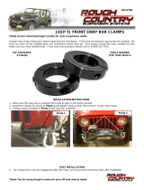
CJ SHACKLE INVERSION KIT
Thank you for choosing Rough Country for all your suspension needs.
Rough Country recommends a certified technician install this system. In addition to these instructions, professional
knowledge of disassemble/reassembly procedures as well as post installation checks must be known. Attempts to install
this system without this knowledge and expertise may jeopardize the integrity and/or operating safety of the vehicle.
Please read instructions before beginning installation. Check the kit hardware against the parts list on this page. Be sure
you have all needed parts and know where they go. Also please review tools needed list and make sure you have
needed tools. PRODUCT USE INFORMATION
Rough Country makes no claims regarding and will not be responsible for any product that is altered.
We will be happy to answer any questions concerning the design, function, and correct use of our products.
NOTICE TO DEALER AND VEHICLE OWNER
Any vehicle equipped with any Rough Country product should have a “Warning to Driver” decal installed on the inside of
the windshield or on the vehicle’s dash. The decal should act as a constant reminder for whoever is operating the vehi-
cle of its unique handling characteristics.
INSTALLING DEALER - it is your responsibility to install the warning decal and forward these installation instructions on
to the vehicle owner for review. These instructions should be kept in the vehicle for its service life.
This kit is designed to ease the harsh ride of the leaf sprung vehicle. Repositioning the shackle to the rear of the spring
allow the leaf spring to move freely through various road conditions. Stock shackles are recommended for this kit.
Installing lifted or longer than factory shackles could create driveshaft vibration and could cause the driveshaft
to separate when the suspension is fully extended.
Kit Contents:
Driver Shackle Bracket
Pass Shackle Bracket
Driver Fr Stationary Bracket
Pass Fr Stationary Bracket
Cross Brace
92506000
Tools Needed:
9/16” Socket / Wrench
3/4” Socket / Wrench
13/16” Socket
7/8” Socket
1 1/8” Socket
Center Punch
Hand Grinder
Hammer
3/8” Drill Bit
1/2” Drill Bit
49/64” Drill Bit
Drill
Tape Measure
Torque Specs:
Size Grade 5 Grade 8
3/8” 30 ft/lbs 35 ft/lbs
1/2” 65 ft/lbs 90 ft/lbs
9/16” 95 ft/lbs 130 ft/lbs
3/4” 185 ft/lbs 280 ft/lbs

FRONT INSTALLATION INSTRUCTIONS
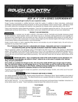
1. Lift front of vehicle and place jack stands under front of frame rails. Remove front wheels.
2. Support front axle assembly with stands and remove the spring u-bolts using a 3/4” socket. See Photo 1.
3. Remove springs using a 3/4 socket on the front shackle and the rear using a 13/16 & 7/8 socket.
4. Remove the lower sway bar link from the spring plate using a 3/4” socket. See Photo 2.
5. Remove the front shackle mounts and the frame mounts from the frame rail. To remove rivets, center punch rivet
head and drill 5/16” deep with a 3/8” drill bit. Then using a chisel and hammer, strike the head of the rivet to remove
it. Use a punch to drive the remaining part of the rivet free.
6. Clean the area’s of the frame where you are going to install the new mounts. If any weld or sharp edges exist, grind
down smooth. Take care not to scar frame rails.
7. Install front brackets with the large ¾” side hole on the outside of the front frame rail. Install the ¾” x 1.25 supplied
bolt into the bracket and frame rail. NOTE: It may be necessary to drill the frame to clearance the ¾” bolt. If so drill at
this time using the new bracket as a locator. Install the 3/8 x 1.25 bolt in the lower side of the bracket and the stock
hardware. See Photo 3. This hole will line up with the factory hole on the underside of the frame rail. Repeat steps
on the other side. The entire system must be installed first, then you can proceed to reinstall the leaf springs and
tighten all hardware using a 1 1/8” wrench on the 3/4” bolt and 9/16” wrench on the other bolts.
8. Install the cross tube brace between the two front brackets using only the 3/8” x 1.25 bolts supplied. The factory
bolts will be installed in this bracket in a later step when the leaf springs are reinstalled. See Photo 4.
Photo 1 Photo 2
Photo 3 Photo 4

9. Install new bracket into place and loosely clamp making sure the ¾” holes on the bracket are on the outside of the
frame rail. Measure 43.50 inches from the center of the bolt hole of the front bracket back along the frame rail to the
center of the bushing hole of the rear bracket. This must be done as accurately as possible. See Photo 5.
10. Using the bracket as a template, mark hole centers with a center punch. Then drill all three holes with a ½”drill bit
going all the way though both sides of the frame rails. Install the 1/2” x 3 1/2” bolt in center hole and then drill the two
remaining holes to 49/64” on the outside of the frame rail. See Photo 4,5,6.
11. Now insert the supplied spacer sleeve into the top holes being very careful not to drop sleeve inside frame rails and
install the ½” x 3 ½” bolts. Install the supplied bushings in the bracket as shown. See Photo 7 & 8. Tighten using a
3/4” socket / wrench.
12. Reverse the springs and install what was the rear part of the leaf springs in the front mount using the supplied 9/16”
x 4 1/2” bolts, nuts and washers. Only slightly tighten at this time. Raise rear of the leaf spring up to meet the new
rear bracket. Note: On the small eye of the spring, remove bushings and install one shim behind each bushing and
replace. See Photo 9 & 10.
Photo 5 Photo 6
Photo 7 Photo 8
Photo 9 Photo 10

13. Install the stock leaf spring plates with the stock u-bolts and tighten using a 3/4” socket. Reinstall the sway bar links
on the spring plate using a 3/4” socket.
14. Install the leaf spring in the rear mount using the stock front shackle bolts washers and nuts.
15. Install the tires / wheels on the Jeep.
16. Lower the vehicle to the ground and tighten all hardware including the spring bolts. The general rule is to tighten the
bolts until the polyurethane bushings slightly bulge. DO NOT over tighten these bolts, as that will contribute to a
rougher ride.
POST INSTALLATION INSTRUCTIONS
1. Check all fasteners for proper torque. Check to ensure for adequate clearance between all rotating, mobile, fixed,
and heated members.
2. Install Warning to Driver decal on sun visor.
3. All components must be retightened after 500 miles, and every three thousand miles after installation.
Thank you for choosing Rough Country for all your suspension needs.
/