Page is loading ...

Thank you for choosing Rough Country for your suspension needs.
Rough Country recommends a certified technician install this system. In addition to these instructions, professional
knowledge of disassemble/reassembly procedures as well as post installation checks must be known. Attempts to install
this system without this knowledge and expertise may jeopardize the integrity and/or operating safety of the vehicle.
Please read instructions before beginning installation. Be sure you have all needed parts and know where they go. Also
please review tools needed list and make sure you have all of the needed tools.
PRODUCT USE INFORMATION
As a general rule, the taller a vehicle is, the easier it will roll. Seat belts and shoulder harnesses should be
worn at all times. Avoid situations where a side rollover may occur. Generally, braking performance and capability are
decreased when larger/heavier tires and wheels are used. Take this into consideration while driving.
Rough Country makes no claims regarding lifting devices and excludes any and all implied claims. We will not be re-
sponsible for any product that is altered. This kit is designed to level the vehicle, if additional list is desired contact you
nearest Rough Country distributor to discus options available.
NOTICE TO DEALER AND VEHICLE OWNER
Any vehicle equipped with any Rough Country product should have a “Warning to Driver” decal installed on the
inside of the windshield or on the vehicle’s dash. The decal should act as a constant reminder for whoever is op-
erating the vehicle of its unique handling characteristics.
INSTALLING DEALER - it is your responsibility to install the warning decal and forward these installation instruc-
tions on to the vehicle owner for review. These instructions should be kept in the vehicle for its service.
INSTALLATION INSTRUTIONS
1. Secure and properly block the tires on the vehicle on a level concrete surface. Jack up the vehicle and place the
front of the vehicle on jack stands.
2. Remove the front wheels and tires. Support the axle with a floor jack.
3. Remove the stock shock absorbers using a 15mm wrench. The stock bolts and nuts on the bottom of the shock will
be reused. Note: Access to the upper shock studs will be obtained through the engine compartment. It also may be
necessary to temporarily remove the washer fluid reservoir to access the driver side upper shock mount nut.
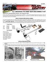
4. Remove the sway bar links on both sides using a T-55 torx bit /19mm wrench and a 15mm for the upper nut .See
Photo 1.
5. Locate and remove the coil clip on the lower coil spring seat. Lower the axle to allow for removal of the coil spring.
Do not over extend the brake lines. The caliper can be removed from the rotor to allow the axle to lower.
6. If needed , use a strut compressor to remove the coil springs. Remove stock coil springs See Photo 2.
92167100B
JEEP XJ 84-01 3” FRONT & 2” REAR SUSPENSION KIT
PHOTO 1 PHOTO 2
*1671BAG3*
1671BAG3

7. Using a strut compressor, compress the new Rough Country coil
spring s and install. Install coil spring clip back onto the lower
coil spring seat.
8. Attach sway bar end links to sway bar and tighten.
9. Install new Rough Country shock absorbers.
10. Install wheels and tires.
11. Jack up the vehicle, remove the jack stands and lower the vehi-
cle to the ground.
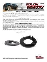
12. Photo #3 shows the caster adjustment on the lower control
arms. The caster will have to be adjusted to insure proper align-
ment.
Proceed to the appropriate installation instructions for the kit with either add-a-leafs in the rear or lift-
ed rear shackles.
ADD-A-LEAF INSTALLTION INSTRUCTIONS
1. Remove rear factory shocks using a 13mm wrench on top and a 3/4” wrench on bottom and retain hardware.
2. Chock the front wheels and jack up the rear of the vehicle and place the vehicle on jack stands. Remove the wheels
and tires.
3. Working from the drivers side, remove the factory u-bolts and lower the axle with a floor jack. Repeat for passenger
side.
4. Separate the springs and install the provided add-a-leaf in the spring pack using a pyramid pattern smallest on the
bottom graduating to largest on top. The factory flat overload leaf should remain on the bottom of the pack (if
equipped).
5. Clamp the spring with the c-clamp and tighten with the supplied center bolt with the nut on top of the spring and to
not leave a gap between the springs. Cut the thread of the bolt smooth with the nut.
6. Realign the center pin in the leaf spring pack to the centering hole on the axle perch.
7. Install new bend clips on spring.
8. Install the tires/wheels.
9. Remove the jack stands and lower the vehicle to the ground. Tighten factory hardware.
LIFTED SHACKLE INSTALLATION INSTRUCTIONS
1. Remove the stock shackle from the frame mount using a 21mm wrench. Locate and either grind or cut off the excess
from the bolt pictured in Photo 4. This will allow the shackle to move rearward
2. Install the new Rough Country lifted shackle and secure with supplied 9/16” x 4” hardware in the top hole and the
14mm x 110mm in the bottom hole.. Do not fully tighten the hardware at this time. See Photo 5.
3. Install the new shocks with factory hardware. Torque the upper using a 13mm wrench and lower bolts using 3/4”
wrench to factory specs. Repeat for other side.
4. Install the tires and wheels. Jack up the vehicle and remove the jack stands. Lower the vehicle to the floor.
5. Torque the frame bolts, and shackle bolts to factory specs using a 21mm wrench.
6. Install the new Rough Country shock absorbers
7. Install the tires/wheels. Remove the jack stands and lower the vehicle to the ground.
8. Tighten factory hardware.
PHOTO 3
PHOTO 5
PHOTO 4

POST INSTALLATION INSTRUCTIONS
Check all fasteners for proper torque. Check to ensure there is adequate clearance between all rotating, mobile, fixed
and heated members. Check steering gear for interference and proper working order. Test brake system.
Perform steering sweep. Check to ensure brake hoses have sufficient slack and will not contact rotating, mobile, or fixed
members, adjust lines/brackets to eliminate interference and maintain proper working order. Failure to perform in-
spections may result in component failure.
Bump stops and extensions must be in place on all vehicles! Note: allowing suspension to over extend by neglecting to
install or maintain stops and extensions may cause serious damage to OE and related components.
Re torque all fasteners after 500 miles. Visually inspect components and re torque fasteners during routine vehicle ser-
vice.
MAINTENANCE INFORMATION
It is the ultimate buyers responsibility to have all bolts/nuts checked for tightness after the first 100 miles and then eve-
ry1000 miles. Wheel alignment steering system, suspension and driveline systems must be inspected by a qualified
professional mechanic at least every 3000 miles.
LIFT KIT TROUBLESHOOTING
Rear driveline:
Acceleration vibration: Caused by the pinion being too high in relation to the transfer case output shaft. On leaf sprung
vehicles, install axle shims to lower pinion accordingly.
Deceleration vibration: Caused by the pinion being too low in relation to the transfer case output shaft. On leaf sprung
vehicles, install axle shims to raise pinion accordingly.
Slip yoke vibration: Caused by excessive angle on the transfer case slip yoke. Very common on vehicles with 2” or more
of lift. Lifts of 2”-3.5” can sometimes be cured with a transfer case drop kit (pinion adjustment may also be required- see
acceleration and deceleration vibration troubleshooting above). If this does not cure it, it will likely require installing a slip
yoke eliminator (SYE) kit and CV drive shaft. Adjust pinion so it is 2 degrees below parallel with CV drive shaft (see ac-
celeration and deceleration vibration troubleshooting above). A transfer case drop kit can usually be omitted with a CV
drive shaft.
Drive shaft bind (84-95 XJ’s): Condition of interference between slip yoke and tube yoke. This is usually only a problem
with over 3.5” lifts. A high travel slip yoke may remedy this. Later XJ's already have the high travel slip yoke and may
instead require an SYE and CV drive shaft (see above slip yoke notes).
High speed wobble:
This is fairly common with y-type steering on lifted XJ's. It is a condition where front tires will shimmy after hitting a bump.
Avoid bias ply tires and wheels with excessive offset. Check for worn or loose parts. In most cases a reduction of posi-
tive caster will eliminate this condition. A good rule of thumb is minimum factory caster and maximum factory toe in. Note
that lift heights increased with coil spacers (or taller coils) may exhibit wobble that cannot be corrected with alignment.
Bump steer:
Caused by improper relationship of drag link and track bar. To correct, center axle again following the instructions sup-
plied with the track bar. Next determine the neutral position of the steering wheel. Adjust the drag link to center the steer-
ing wheel

Thank you for purchasing a Rough Country Suspension System.
By purchasing any item sold by Rough Country, LLC, the buyer expressly warrants that he/she is in compliance with all
applicable , State, and Local laws and regulations regarding the purchase, ownership, and use of the item. It shall be
the buyers responsibility to comply with all Federal, State and Local laws governing the sales of any
items listed, illustrated or sold. The buyer expressly agrees to indemnify and hold harmless Rough
Country, LLC for all claims resulting directly or indirectly from the purchase, ownership, or use of the
items.
/