Page is loading ...

06-308
MAR16
ASSEMBLY AND INSTALLATION
INSTRUCTIONS
ATTENTION!
THESE INSTRUCTIONS MUST REMAIN WITH PLATFORM OWNER
STEEL METER DIVING STANDS
**PROFESSIONAL INSTALLATION RECOMMENDED**
POOL WATER ENVELOPE DIMENSIONS MUST MEET OR EXCEED ANSI/APSP/ICC-5
2011 STANDARDS FOR THIS STAND. ALL WATER ENVELOPE DIMENSIONS FOR
PUBLIC SWIMMING POOLS MUST MEET OR EXCEED THE ANSI/APSP/ICC-1 2014
STANDARD FOR PUBLIC SWIMMING POOLS. USE ONLY WITH A COMPATIBLE S.R.
SMITH DIVING BOARD. S.R. SMITH DIVING BOARDS AND RELATED EQUIPMENT ARE
FOR IN-GROUND POOLS ONLY. DO NOT USE WITH OTHER POOLS, DOCKS, ETC.
USE WITH AN IMPROPERLY-SIZED POOL, INCOMPATIBLE BOARD, OR IMPROPER
INSTALLATION MAY RESULT IN DEATH OR SERIOUS INJURY.

2
TABLE OF CONTENTS
RESIDENTIAL MOUNTING KIT ................................................................................................................... 3
COMMERCIAL MOUNTING KIT .................................................................................................................. 4
HANDRAIL INSTALLATION INSTRUCTIONS ............................................................................................. 5
RESIDENTIAL INSTALLATION INSTRUCTIONS ........................................................................................ 6
COMMERCIAL INSTALLATION INSTRUCTIONS ....................................................................................... 9
ARTICLE 5 – POOL DIMENSIONS AND TOLERANCES
EXTRACTED FROM THE ANSI/APSP/ICC-5 2011
AMERICAN NATIONAL STANDARD FOR RESIDENTIAL INGROUND SWIMMING POOLS ................... A
SELECTED SECTIONS EXTRACTED FROM
ANSI/APSP/ICC-1 2014
AMERICAN NATIONAL STANDARD FOR PUBLIC SWIMMING POOLS .................................................... I
SRS AUSTRALIA, PTY LTD
12 Enterprise St
Richlands QLD 4077
Australia
Phone 07 3812 2283 • Fax 07 3812 1187
www.srsmith.com/au
S.R. SMITH, LLC
CORPORATE HEADQUARTERS
P.O. Box 400 • 1017 S.W. Berg Parkway
Canby, Oregon 97013
USA
Phone (503) 266 2231 • Fax (503) 266 4334
www.srsmith.com
Assembly and Installation Instructions for S.R. Smith’s
STEEL METER DIVING STANDS:
1/2 Meter 3/4 Meter 1 Meter
8’ Board (70-209-501) 10’ Board (70-209-510) 10’ Board (70-209-520)
10’ Board (70-209-502) 12’ Board (70-209-512) 12’ Board (70-209-522)
REGISTER YOUR S.R. SMITH PRODUCT AT
www.srsmith.com/en/customer-service/product-registration
Visit srsmith.com for information on the complete line of
S.R.Smith pool products.

3
22
1
30
21
29
2816
17
10
20
42
42
REAR STEP 8
15
12
13
14
2515
26
27
18
9
33
31
32
5
7
11
7
JIG (6 BOLTS)
MOUNTING
ANCHOR
DIVING STAND
STEEL METER
19
24
23
22
25
1/2" JIG CAP-
RED (2 EA.)
YELLOW (4 EA.)
DIVING BOARD
1/2" JIG CAP-
STEEL METER
4
3
2
22
12
5
FIGURE A
FIGURE B
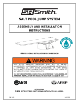
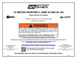
RESIDENTIAL MOUNTING KIT (67-209-911-SS)_____
1. 1/2" X 4-1/2" CARRIAGE BOLT-S/S (2 EA.)
2. 1/2" LOCK WASHER S/S (2 EA.)
3. 1/2" HEX NUT S/S (2 EA.)
4. 1/2" PLASTIC NUT CAP (2 EA.)
5. 1/2" X 2" BLACK RUBBER MOUNTING
WASHER (4 EA.)
6. 1/2" X 2" FLAT WASHER S/S (2 EA.)
7. WHITE PLASTIC RECESSED MOUNTING
WASHER ASSY' (2 EA.)
1/2 METER BOLT KIT (71-209-542-SS)____________
8. 1/2" PLASTIC NUT CAP (6 EA.)
9. 3/8" X 2" STEP BOLT S/S (2 EA.)
10. 3/8" LOCK WASHER S/S (2 EA.)
11. 1/2" X 3-1/2" CARRIAGE BOLT S/S (2 EA.)
12. 1/2" X 1-3/8" FLAT WASHER S/S (8 EA.)
13. 1/2" LOCK WASHER S/S (6 EA.)
14. 1/2" HEX NUT S/S (6 EA.)
15. 1/2" X 1-1/2" ROUND NYLON WASHER (8
EA.)
16. 3/8" X 7/8" NYLON PROTECTIVE WASHER
(2 EA.)
17. 3/8" X 1" FLAT WASHER S/S (2 EA.)
18. 3/8" HEX NUT S/S (2 EA.)
3/4 & 1 METER BOLT KIT (71-209-543-SS)_________
19. 1/2" PLASTIC NUT CAP (6 EA.)
20. 3/8" X 2" STEP BOLT S/S (2 EA.)
21. 3/8" LOCK WASHER S/S (2 EA.)
22. 1/2" X 1-3/8" FLAT WASHER S/S (10 EA.)
23. 1/2" LOCK WASHER S/S (6 EA.)
24. 1/2" HEX NUT S/S (6 EA.)
25. 1/2" X 1-1/2" ROUND NYLON WASHER (8
EA.)
26. 1" SPACER SCHEDULE 40 PIPE S/S (2 EA.)
27. 15" RUBBER PAD (1 EA.)
28. 3/8" X 7/8" NYLON PROTECTIVE WASHER
(2 EA.)
29. 3/8" X 1" FLAT WASHER S/S (2 EA.)
30. 3/8" HEX NUT S/S (2 EA.)
METER FULCRUM KIT (71-209-544)______________
31. 18" METER FULCRUM PLATE (1 EA.)
32. 18" METER FULCRUM PAD (1 EA.)
33. 20” RUBBER MOUNTING PAD (1 EA.)
RESIDENTIAL MOUNTING KIT
BOARD
THICKNESS: 6" MIN.
DECK END WATER END
DIVING
WIDTH: 4' MIN.
LENGTH: 8' (MIN.)
CONCRETE SLAB
WA
HO
W
S
1-1/2"
SR87-444
05
NOTES:
●
USED ONLY WHEN INSTALLING HANDRAILS
USED ONLY ON 3/4 AND 1 METER STANDS
PARTS WITH TWO BUBBLES:
LEFT IS FOR 1/2 METER
RIGHT IS FOR 3/4 & 1 METER

4
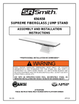
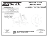
FIGURE C
BOLT PATTERN
17"
3"
10"
4"6-1/2"
SEE FIG. 2
1
22
3
2
11
42
42
REAR STEP 8
15
12
13
14
2515
26
27
JIG (6 BOLTS)
MOUNTING
ANCHOR
DIVING STAND
STEEL METER
19
24
23
22
25
1/2" JIG CAP-
RED (2 EA.)
YELLOW (4 EA.)
DIVING BOARD
1/2" JIG CAP-
STEEL METER
7
6
5
22
12
3
COMMERCIAL MOUNTING KIT
18” COMMERCIAL MOUNTING KIT (67-209-903-SS)
1. 1/2" X 5" CARRIAGE BOLT S/S (2 EA.)
2. 18" TOP MOUNTING PLATE (1 EA.)
3. 18" RUBBER MOUNTING PAD (2 EA.)
4. 18" BOTTOM MOUNTING PLATE (1 EA.) DO NOT USE
5. 1/2" LOCK WASHER S/S (2 EA.)
6. 1/2" HEX NUT S/S (2 EA.)
7. 1/2" PLASTIC NUT CAP (2 EA.)
1/2 METER BOLT KIT (71-209-542-SS)
8. 1/2" PLASTIC NUT CAP (6 EA.)
9. 3/8" X 2" STEP BOLT S/S (2 EA.)
10. 3/8" LOCK WASHER S/S (2 EA.)
11. 1/2" X 3-1/2" CARRIAGE BOLT S/S (2 EA.)
12. 1/2" X 1-3/8" FLAT WASHER S/S (8 EA.)
13. 1/2" LOCK WASHER S/S (6 EA.)
14. 1/2" HEX NUT S/S (6 EA.)
15. 1/2" X 1-1/2" ROUND NYLON WASHER (8 EA.)
16. 3/8" X 7/8" NYLON PROTECTIVE WASHER (2 EA.)
17. 3/8" X 1" FLAT WASHER S/S (2 EA.)
18. 3/8" HEX NUT S/S (2 EA.)
3/4 & 1 METER BOLT KIT (71-209-543-SS)
19. 1/2" PLASTIC NUT CAP (6 EA.)
20. 3/8" X 2" STEP BOLT S/S (2 EA.)
21. 3/8" LOCK WASHER S/S (2 EA.)
22. 1/2" X 1-3/8" FLAT WASHER S/S (10 EA.)
23. 1/2" LOCK WASHER S/S (6 EA.)
24. 1/2" HEX NUT S/S (6 EA.)
25. 1/2" X 1-1/2" ROUND NYLON WASHER (8 EA.)
26. 1" SPACER SCHEDULE 40 PIPE S/S (2 EA.)
27. 15" RUBBER PAD (1 EA.)
28. 3/8" X 7/8" NYLON PROTECTIVE WASHER (2 EA.)
29. 3/8" X 1" FLAT WASHER S/S (2 EA.)
30. 3/8" HEX NUT S/S (2 EA.)
NOTES:
●
USED ONLY WHEN INSTALLING HANDRAILS
USED ONLY ON 3/4 AND 1 METER STANDS
PARTS WITH TWO BUBBLES:
LEFT IS FOR 1/2 METER
RIGHT IS FOR 3/4 & 1 METER
TIGHTENING SCHEDULE
1. SECURE BOARD TO STAND WITH MOUNTING HEX NUTS
a. FIBERGLASS: 20-25 FT-LBS
b. ALUMINUM: 35-40 FT-LNS
2. SECURE STAND TO JIG WITH ANCHOR HEX NUTS 40-50 FT-LBS

5
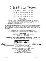
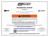
FIGURE D
37
41
35
HANDRAIL
DIVING STAND
TOP PLATFORM
36
40
35
37
35
36 40
34
36
40
37
39
35
38
FIGURE E
HANDRAILS ARE OPTIONAL ON ALL 1/2 & 3/4 METER STANDS
HANDRAILS ARE REQUIRED ON ALL 1 METER STANDS
1. Bolt the handrail bracket assemblies on the inside of the stand top platform as shown in FIGURE
C for each of the four locations.
2. Insert the end of the handrail into the bracket through the holes so the holes line up with the
bracket bolt holes.
3. Secure hex nut with 40 – 50 ft-lbs.
4. When installing or reinstalling diving board after handrails have been installed on diving stand, be
sure to use the two 18” Rubber Mounting Pads (#42) between bottom of diving board and top of
stand (See FIGURE B or FIGURE C). This shims the board up so that it will not hit the 3/8” x 5-
1/2” Hex Bolt and damage the bottom of the board.
METER HANDRAIL BOLT KIT (71-209-561-SS)
34. 3/8" X 5-1/2" HEX BOLT S/S (4 EA.)
35. 3/8" X 7/8" NYLON PROTECTIVE WASHER
(20 EA.)
36. 3/8" HEX NUT S/S (12 EA.)
37. 3/8" X 1" FLAT WASHER S/S (12 EA.)
38. 3/8" X 3" HEX BOLT S/S (4 EA.)
39. 3/8" X 1" HEX BOLT S/S (4 EA.)
40. 3/8" LOCK WASHER S/S (12 EA.)
41. HANDRAIL BRACKET ASSY' (4 EA.)
42. 18" RUBBER MOUNTING PAD (2 EA.)
HANDRAIL INSTALLATION INSTRUCTIONS

6
TABLE 1– STEEL METER DIVING STAND INSTALLATION CHART
RESIDENTIAL POOLS
Refer to Figure A.
Model
STEEL
METER
Diving
Board
Length
Distance For
Setting Front Bolt
of Jig From Water’s
Edge
“S”
Pool Type
(ANSI/APSP/ICC-5
2011)
Min.
Overhang ±
3” (76mm)
“WA*”
Max. Height of
Board Above
Water
“HOW”
1/2 METER
1/2 METER
1/2 METER
1/2 METER
1/2 METER
3/4 METER
1/2 METER
1/2 METER
3/4 METER
3/4 METER
1 METER
1 METER
8’
8’
10’
8’
10’
10’
8’
10’
10’
12’
10’
12’
39”
33”
45”
27”
39”
46”
21”
33”
40”
51”
43”
57”
II
III
III
IV
IV
IV
V
V
V
V
V
V
18”
24”
24”
30”
30”
30”
36”
36”
36”
36”
36”
36”
20”
26”
26”
30”
30”
30”
40”
40”
40”
40”
40”
40”
IMPORTANT: The distance for setting the front bolt of the jig “S” from the water’s edge is valid
only if the minimum water depth is maintained at the tip of the board noted at point A in
ANSI/APSP/ICC-5 2011, Figure 3 and Table 1. If minimum water depth is not maintained the
distance “S” must be adjusted accordingly.
BE SURE CONCRETE DECK SURROUNDING ANCHOR JIG COMPLIES WITH MINIMUM
DIMENSIONS IN FIGURE A.
**Professional installation recommended**
**Improper installation voids S.R. Smith’s Limited Product Warranty**
1. Verify that the pool water envelope dimensions meet or exceed ANSI/APSP/ICC-5 2011
standards for this board and stand. Excerpts from the applicable ANSI/APSP/ICC-5 2011
standard are attached and more information on safe installation is available at
www.srsmith.com. Warning: using the diving board and stand with an improperly-sized
pool may result in death or serious injury.
2. Verify that the board is compatible with the S.R. Smith diving board stand. A matrix of compatible
products is attached and available at www.srsmith.com.
3. Identify installation site. Board must be placed at deep end of pool on centerline. Set Steel Meter
six bolt jig in accordance with the Installation Chart above and FIGURE A, with the two “RED”
capped bolts closest to the pool.
RESIDENTIAL INSTALLATION INSTRUCTIONS
*WA DIMENSION IS VALID ONLY IN CONJUNCTION WITH MIN. DEPTH AT POINT A (SEE ANSI/APSP/ICC-5 2011
FIGURE 3 AND TABLE 1) FOR POOL TYPE.
**When coping is used do not set front bolt of jig closer than 3” (76 mm) from the back edge of coping.

7
CAUTION: Before pouring concrete around Jig, check the bolt pattern of Jig to FIGURE C. It is
possible that they have become misaligned through shipping and handling.
4. Make sure bolts project out of concrete 1-1/2" with ample concrete depth below Jig. Refer to
FIGURE A for minimum deck thickness, width and length.
5. When finishing deck surface, maintain level deck where Jig bolts project out so that the stand
makes uniform contact with deck surface.
6. Before mounting stand, chisel away any excess concrete that may have built up around Jig bolts
and remove the red and yellow bolt caps
7. Place stand over Jig bolts and secure according to FIGURE B or FIGURE C, depending upon
mounting kit used. Tighten ANCHOR hex nuts. TIGHTENING SCHEDULE on page 3 when
tightening all MOUNTING and ANCHOR hex nuts.
8. With Steel Meter Stand properly secured, select board size according to TABLE 1. The
installation sequence is as follows:
(I) Meter Fulcrum (FIGURE B)
(II) Handrails (FIGURE D on page 5)
(III) Rear Step and Board (FIGURE B on page 3)
9. The Rear Step and Board may be installed with either the Residential Mounting Kit (FIGURE B)
or the Commercial Mounting Kit (FIGURE C). Tighten MOUNTING hex nuts.
10. The top surface of the diving board from the deck end to the tip end shall be level or have an
upward slope of 5/8” per foot (16mm: 305mm) maximum. Elevation difference shall not exceed 6”
(152mm) from the deck end to the tip of the board. There shall be no downward slope towards
the water. The slope shall be measured using a level as shown in FIGURE F.
NOTICE:
S.R. SMITH CANNOT GUARANTEE
CUSTOMER’S CONCRETE STRENGTH OR
THICKNESS
IMPORTANT NOTICE:
IT IS NECESSARY TO USE AN ANTI-SEIZE
COMPOUND ON ALL STAINLESS STEEL
HARDWARE. FAILURE TO USE ANTI-SEIZE
COMPOUND MAY RESULT IN GALLING AND
SEIZING OF THE HARDWARE.
ONLY ONE PERSON ON DIVING PLATFORM AT A TIME
WITH A MAXIMUM WEIGHT OF 250 LBS (113kg)

8
Pool
Type
MAX. DIVING
BOARD
LENGTH
MAX. HEIGHT
OVER WATER
AT POINT A
CROSS SECTIONAL
DIMENSIONS AT
POINT A
CROSS SECTIONAL
DIMENSIONS AT POINT B
DBL** HOW** F G H J K L M N
0 DIVING EQUIPMENT IS PROHIBITED
I 6' (1.83m) DB/
6’ (1.83m) JB
20”
(50.8cm)
2'-9"
(83.8cm)
5'-0"
(1.52m)
4'-0"
(1.22m)
7'-2 1/2"
(2.20m)
7'-6"
(2.29m)
6'-0"
(1.83m)
3'-9"
(1.14m)
2'-1 1/2"
(64.8cm)
II 8' (2.44m) DB/
6’ (1.83m) JB
20"
(50.8cm)
2'-9"
(83.8cm)
3'-10"
(1.17m)
4'-2"
(1.27m)
7'-2 1/2"
(2.20m)
7'-6"
(2.29m)
6'-8"
(2.03m)
3'-9"
(1.14m)
2'-1 1/2"
(64.8cm)
III 10' (3.05m) DB/
8’ (2.44m) JB
26"
(66cm)
2'-9"
(83.8cm)
4'-4 3/4"
(1.34m)
4'-4 1/2"
(1.33m)
7'-5 1/2"
(2.27m)
8'-0"
(2.44m)
6'-7"
(2.01m)
3'-11
1/2"
(1.21m)
1'-7 1/2"
(49.5cm)
IV 10' (3.05m) DB/
8’ (2.44m) JB
30"
(76.2cm)
2'-9"
(83.8cm)
5'-10 1/2"
(1.79m)
3'-10"
(1.17m)
7'-8"
(2.34m)
8'-6"
(2.59m)
8'-3"
(2.51m)
5'-7"
(1.70m)
2'-7"
(78.7cm)
V 12' (3.66m) DB/
8’ (2.44m) JB
40"
(1m)
2'-9"
(83.8cm)
6'-2"
(1.88m)
3'-11
1/2"
(1.21m)
7'-9 1/2"
(2.37m)
9'-0"
(2.74m)
8'-2 1/2"
(2.50m)
5'-9"
(1.75m)
2'-1"
(63.5cm)
NOTES:
1. ** ABBREVIATIONS: DBL = Diving Board Length, DB = Diving Board, JB = Jump Board, HOW = Height Over Water.
2. IMPORTANT: The walls of a Type I Pool, when defining the Maximum Diving Water Envelope shall be plumb.
3. All dimensions are minimum, except where noted as maximum.
4. One half (1/2) the width shown at each point shall be available on each side of the diving equipment centerline.
5. Minimum water depth under tip of diving board (Point A) is important to maintain.
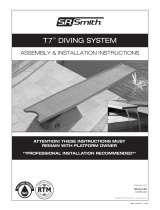
FIGURE G – Minimum Cross Sections (Refer to ANSI/APSP/ICC-5 2011 Figure 3 on Page B)
FIGURE F
TABLE 2 – S.R. SMITH RESIDENTIAL POOL SPECIFICATIONS
IMPORTANT: Maximum diving board length, maximum height over water at point A, and minimum cross section
dimensions at point A and B shall be in accordance with Table 2 and FIGURE G.
TABLE 3 – Minimum Headroom Requirements
Minimum unobstructed headroom from the top of the manufactured diving equipment is specified below.
Pool Type Minimum Headroom Above
Diving Surface
I 12 feet (3.7 m)
II 12 feet (3.7 m)
III 13 feet (4 m)
IV 13 feet (4 m)
V 14 feet (4.3 m)
(SEE TABLE 2 FOR DIMENSIONS F-N)
K
J
B
L
C
L
SYM.
M
N
L
CSYM.
D
6" R. (MAX.)
H
A
L
C
SYM.
C
L
C
SYM.
2'-3" R. (MAX.)
G
F
CROSS SECTION AT POINT C
WATER LEVEL WATER LEVEL
CROSS SECTION AT POINT A CROSS SECTION AT POINT D
CROSS SECTION AT POINT B
WATER LEVEL
WATER LEVEL
MINIMUM CROSS SECTIONS

9
TABLE 4 – STEEL METER DIVING STAND INSTALLATION CHART
PUBLIC POOLS
Refer to Figure A
Model
STEEL
METER
Diving
Board
“DB”
ANSI/APSP/ICC-
1 2014 Pool
Type
Distance For
Setting Front
Bolt of Jig From
Water’s Edge
“S”
Min. Overhang
+3” (76mm)
“WA*”
Max. Height of
Board Above
Water
“HOW”
1/2 METER
1/2 METER
1/2 METER
1/2 METER
3/4 METER
3/4 METER
1/2 METER
3/4 METER
3/4 METER
1 METER
1 METER
3/4 METER
1 METER
8’
10’
8’
10’
10’
12’
10’
10’
12’
10’
12’
12’
12’
VI
VI
VII
VII
VII
VII
VIII
VIII
VIII
VIII
VIII
IX
IX
27”
39”
21”
33”
40”
51”
21”
28”
39”
31”
45”
15”
21”
30”
30”
36”
36”
36”
36”
48”
48”
48”
48”
48”
72”
72”
26”
26”
30”
30”
30”
30”
40”
40”
40”
40”
40”
120”
120”
COMPLY WITH LOCAL GOVERNMENT REGULATIONS FOR PUBLIC SWIMMING POOLS IF THEY
EXCEED THE ANSI/APSP/ICC-1 2014 STANDARD
*L1 DIMENSION IS VALID ONLY IN CONJUNCTION WITH D1 DEPTH FOR TYPE POOL AND BOARD
TO BE USED.
L1 is WA in Figure A and Installation Chart.
NOTE: When coping is used do not set front bolt of jig closer than 3” from the back edge of coping.
BE SURE CONCRETE DECK SURROUNDING ANCHOR JIG COMPLIES WITH MINIMUM
DIMENSIONS SHOWN IN FIGURE A FOR POOL TYPE AND BOARD TO BE USED.
1. Carefully read pages I through VI in this booklet, which contains the applicable articles of the
ANSI/APSP/ICC-1 2014 STANDARD FOR PUBLIC SWIMMING POOLS.
2. The Steel Meter six-bolt Jig should be set in accordance with the INSTALLATION CHART above
and FIGURE A, with the two" RED" capped bolts closest to the pool. This will give the desired
minimum overhang. Board must be placed at deep end of pool on centerline.
CAUTION: Before pouring concrete around Jig, check the bolt pattern of Jig to FIGURE C. It is
possible that they have become misaligned through shipping and handling.
3. Make sure bolts project out of concrete 1-1/2" with ample concrete depth below Jig. Refer to
FIGURE A for minimum deck thickness, width and length.
COMMERCIAL INSTALLATION INSTRUCTIONS

10
4. When finishing deck surface, maintain level deck where Jig bolts project out so that the stand
makes uniform contact with deck surface.
5. Before mounting stand, chisel away any excess concrete that may have built up around Jig bolts
and remove the red and yellow bolt caps.
6. Place stand over Jig bolts and secure according to FIGURE B or FIGURE C, depending upon
mounting kit used. Tighten ANCHOR hex nuts. TIGHTENING SCHEDULE on page 3 when
tightening all MOUNTING and ANCHOR hex nuts.
7. With Steel Meter Stand properly secured, select board size according to TABLE 1. The
installation sequence is as follows:
(I) Meter Fulcrum (FIGURE B)
(II) Handrails (FIGURE D on page 5)
(III) Rear Step and Board (FIGURE B on page 3)
8. The Rear Step and Board may installed with either the Residential Mounting Kit (FIGURE B) or
the Commercial Mounting Kit (FIGURE C). Tighten MOUNTING hex nuts.

A
5 Pool Dimensions and Tolerances
5.1 General requirements. Design dimensions shall comply with the specifications in this standard. The pool shall be constructed to
these design dimensions within the tolerances listed in 5.1.1.
5.1.1 Construction tolerances. There shall be construction tolerances allowed on dimensional designs. The length,
width, and depth shall be limited to a tolerance of plus or minus 3 in. (±76 mm). All other dimensions shall be limited to a
tolerance of ±2 in. (±51 mm), unless otherwise specified.
NOTE: Negative construction tolerances shall not be applied to the shallow area dimensions of the Minimum Diving
Envelope given in Table 1, p. 4.
5.2 Perimeter shape. No limits are specified for shapes of pools. Consideration shall be given to circulation and safety to the user.
5.3 Walls–Requirements
5.3.1 Walls in the shallow area and deep area of the pool shall not slope greater than 11° (5:1 slope ratio) to a transition
point of the floor (see Figure 1). The transition to the bottom of the pool between points D and E (see Figure 3, p. 5) shall
not be less than 2 ft 3 in. (686 mm) below the waterline.
5.3.2 As shown in Figure 2, at the depths of (A) and (B), the walls are permitted to continue to join the floor.
ARTICLE 5 – POOL DIMENSIONS AND TOLERANCES
EXTRACTED FROM THE ANSI/APSP/ICC-5 2011
AMERICAN NATIONAL STANDARD FOR RESIDENTIAL INGROUND SWIMMING POOLS

B

C
5.4 Offset Ledges
5.4.1 Offset ledges shall be a maximum of 8 in. (203 mm) wide.
5.4.1.1 Offset ledges located less than 42 in. (1.07 m) below waterline shall be proportionately less than 8 in. (203 mm)
wide and fall within 11° from plumb, measured from the top of the waterline (see Figure 4).
5.5 Floor slopes. Floor slopes shall be reasonably uniform and comply with paras. 5.5.1 through 5.5.3.
5.5.1 The slope of the floor from the shallow end wall towards the deep area shall not exceed a 1:7 incline to the point of
the first slope change, if any (D–E) as shown in Figure 5.
5.5.2 Changes in slope between shallow and deep areas shall be at a minimum water depth of 2 ft 9 in. (838 mm) and be
at least 6 ft (1.83 m) from the shallow end, except as specified in para. 6.3.
5.5.3 The slope of the floor shall not exceed a 1:3 incline under the lengths (B–D) of the Diving Envelope (see Figure 5).
5.6 Shallow end water depths. Water depth in the shallow area shall be a minimum of 2 ft 9 in. (838 mm), except for those
locations specified in para. 6.3 “Shallow End Detail for Beach and Sloping Entries.”
5.7 Manufactured diving equipment for in-ground swimming pools (diving board/stand combination, manufactured platform, or field
fabricated)
5.7.1 When manufactured or field fabricated diving equipment is installed, it shall conform to the specifications set forth in
paras. 5.7–5.9. It shall be located in the deep area of the pool to provide the minimum dimensions as shown in para. 5.8,
and shall be installed in accordance with manufacturer’s instructions.
5.7.1.1 Manufactured or field fabricated diving equipment shall be located directly above Point A. Diving equipment shall
not be installed on Type O pools (see Table 1).
5.7.1.2 Maximum elevation of a diving board above the water shall be in accordance with manufacturer’s installation
instructions. Raised decking may be installed around the diving board up to level with the top of the board.
5.7.2 Manufactured diving equipment installation and use instructions shall be provided by the diving equipment manufacturer and
shall specify the minimum water dimensions required for each diving board and diving stand combination. They shall refer to the
diving envelope type of their choice by dimensionally relating their products to Point A on the diving envelopes as shown in Figure 3,
Table 1, and paras. 5.8.1–5.8.3
5.7.2.2 Diving equipment shall be permanently labeled and affixed to the diving equipment or jump boards and include,
but not be limited to the following:
manufacturer’s diving equipment name and address
date of manufacture
minimum diving envelope
maximum weight limitations.
5.7.2.3 Diving equipment shall have slip-resisting tread surfaces.
5.8 Figure 3 diagrams show dimension points referred to in Table 1.
5.8.1 Point A: Point A is the point from which all other forward dimensions of width, length, and depth are then
established for the Minimum Diving Water Envelope. If the tip of the diving board or diving platform overhang is located at
a distance of WA or greater from the deep end wall and the water depth at that location is equal to or greater than the
water depth requirement at Point A (see Table 1), then the point on the water surface directly below the center of the tip of
the diving board or diving platform shall be identified as Point A.
5.8.1.2 Location of Point A: The minimum Diving Water Envelope dimensions for pools with manufactured diving
equipment shall be taken from Point A as shown in Figure 3. Point A shall be defined as the point on the water surface
where the water depth is required at Point A and is provided at a distance of WA as shown in Table 1 from the deep end

D
wall. The center of the tip of the diving board,
platforms, manufactured or field fabricated
shall be located directly above Point A.
5.8.1.3 Point A as shown in Figure 3 and Table
1 shall be the reference point of origin for all
dimensions defining the minimum diving
envelope.
5.8.2 Type O pools (where diving is prohibited) shall not
be limited in width, length, or water depth except as
specifically provided for in this standard.
Pool Type I 42 in. (1.07 m)
Pool Type II 42 in. (1.07 m)
Pool Type III 50 in. (1.27 m)
Pool Type IV 60 in. (1.52 m)
Pool Type V 69 in. (1.75 m).
5.8.3 Location of equipment and pool features in the
minimum diving envelope. If the pool is designed for use
with diving equipment, all steps, pool stairs, ladders,
underwater benches, offset ledges special features and
other accessory items or any parts thereof, these
features shall be located outside the Minimum Diving
Envelope (see Figure 6).
5.9 Stationary diving platform(s) and diving rock(s).
Stationary diving platform(s) and diving rock(s) built on
site field fabricated shall be allowed to be flush with the
wall and located in the diving area of the pool. Point A
shall be in front of the wall at the platform or diving rock
centerline. Diving rocks or platforms are prohibited on
Pool Type O.
5.10 Stationary diving platform(s) and diving rock(s)
5.10.1 Stationary diving platform(s) and diving
rock(s) shall not be permitted on Pool Type O.
5.10.2 The maximum height of the stationary
diving platform or diving rock above the waterline shall be
as follows:
Pool Type I 42 in. (1.07 m)
Pool Type II 42 in. (1.07 m)
Pool Type III 50 in. (1.27 m)
Pool Type IV 60 in. (1.52 m)
Pool Type V 69 in. (1.75 m).
5.10.3 The diving equipment manufacturer shall specify
minimum headroom above water.
5.11 Swimming pool slides
5.11.1 Slides, where installed, shall be installed in accordance
with the manufacturer’s specifications and comply with the
U.S. Consumer Product Safety Commission (CPSC) Standard
for Swimming Pool Slides as published in the Code of Federal Regulations, 16 CFR Ch. II, Part 1207.
5.11.2 Slides constructed on-site are not covered by this standard.
NOTE: For consumer safety information, warnings, and education programs, see Appendices F, G, and H.

E
Appendix F
Recommendations to Warn Against Shallow Water Diving
This appendix is not part of the American National Standard ANSI/APSP/ICC-5 2011. It is included for information only.
Recommended methods to warn against shallow water diving may
include, but not be limited to:
A. Safety Signs
It is an open question before the Human Factors Society and others
whether signage is an effective means that will modify human
behavior to prevent accidents.
If warning signs are used to warn against shallow water diving, the
signage should be in compliance with ANSI-Z535 1998 Series of
standards for safety signs and colors or the latest revision.
This sign is based upon a study entitled “Design of Swimming Pool
Warnings.” This sign has been reviewed by the staff of the U.S.
Consumer Product Safety Commission and supports its use.
B. Additional Signage Use
The ANSI-Z535 Series of Standards reflects the consensus of
various experts on warning sign appearance and content. Signage, which is consistent with the ANSI-Z535 Standards, is permitted
to be added to components, equipment, facilities, or installations, to provide additional information.
Manufacturers are permitted to either affix additional signage to their products or packaging, or to supply the signage with the
product to be affixed at the time of installation
Appendix G
Safety Considerations and Warning Recommendations
This appendix is not part of the American National Standard ANSI/APSP/ICC-5 2011. It is included for information only.
The Association of Pool & Spa Professionals (APSP) suggests that the builders/installers of swimming pools advise the initial
owner/operator of a residential pool of the following:
Warning Recommendations: The APSP suggests the builder/installer advise the pool owner of the risk of drowning, especially for
children under the age of five, and the risk of diving into shallow water in one or more of the following ways: verbally, through
publications or signage. The following are suggested recommendations:
Lifesaving Equipment: The APSP suggests the builder/installer advise the pool owner/operator that basic lifesaving equipment
including one or more of the following items should be on hand at all times:
• A light, strong, rigid pole not less than twelve feet (12', 3.7 m) long
• A minimum one fourth inch (6 mm) diameter throwing rope as long as one and one-half (1½) times the maximum width of the pool
or 50 feet (15.2 m), whichever is less, which has been firmly attached to a Coast Guard-approved ring buoy having an outside
diameter of approximately 15 in. (381 mm), or some other similar flotation device.
Safety Considerations for Pool Owner/Operators: For additional safety information see www.APSP.org.
This standard does not replace good judgment and personal responsibility. In permitting use of the pool by others, owners/operators
must consider the skill, attitude, training, and experience of the expected user. It is the pool owner/operator’s responsibility to learn,
understand, and enforce these basic safety principles and rules:
• Encourage children to learn how to swim.
• Never allow diving, jumping or sliding into shallow water.
• Adequate adult supervision is required when the pool is in use.
• Adequate adult supervision is always required when children are present.
• Encourage parents to learn CPR.
• Encourage children to never swim alone.
• Keep all electrical radios, speakers and other appliances away from the swimming pool.
• Do not allow roughhousing and horseplay.
• Keep deck clean and clear of objects that may create a hazard.
• Keep all breakable objects out of the pool area.
• Alcohol consumption and pool activities do not mix. Never allow anyone to swim, dive or slide under the influence of alcohol or
drugs.

F
Do’s and Don’ts for Diving into swimming pools with manufactured diving equipment, diving rocks, and stationary diving
platforms:
• Do know the shape of the pool bottom and the water depth before you dive or slide headfirst.
• Do plan you path to avoid submerged obstacles, surface objects, or other swimmers.
• Do hold your head up, arms up, and steer up with your hands.
• Do practice carefully before you dive or slide.
• Do test the diving board for its spring before using.
• Do remember that when you dive down, you must steer up.
• Do dive straight ahead, not off the side of the diving board.
• Don't drink and dive.
• Don't dive or slide headfirst in the shallow part of the pool.
• Don't dive from any place that is not specifically designed for diving .
• Don’t ever dive head first into shallow water (5 feet or less).
• Don't dive across the narrow part of the pool.
• Don't run and dive.
• Don't dive from any place that is not specifically designed for diving.
• Don't engage in horseplay on diving or sliding equipment.
• Don't use diving equipment as a trampoline.
• Don't do a back dive.
• Don't try fancy dives; keep the dives simple.
• Don't dive or slide headfirst at or through objects such as inner tubes.
• Don't put diving or sliding equipment on a pool that wasn't designed for it.
• Don't swim or dive alone.
• Don't dive into unfamiliar bodies of water.
Rules for General Use of Swimming Pool Slides.* Under all circumstances you should prohibit:
• All headfirst entry from slide.
• Horseplay.
• Any slide entries by non-swimmers into deep water, to protect them from drowning.
• Standing on the top of a slide or outside the guardrails.
• Jumping from a slide.
• Diving from a slide.
• Sliding into areas with submerged obstacles, surface objects, or other swimmers.
• Do not engage in extended breath holding activities underwater
* Consult safe use instructions of the pool slide manufacturer
Appendix H
Safety Brochures and Education Programs
This appendix is not part of the American National Standard ANSI/APSP/ICC-5 2011. It is included for information only.
Consumer awareness information is available from the following sources:
• “The Sensible Way to Enjoy Your Inground Swimming Pool” Published by the Association of Pool & Spa Professionals (APSP)
• “Children Aren't Waterproof” Published by the APSP
• “Be Safety Aware” Published by the APSP
• “Layers of Protection” Published by the APSP
• “Pool and Spa Emergency Procedures for Infants and Children” Published by the APSP
• “Knowing How to Dive” Published by the APSP
Copies of the above brochures are available free from the APSP at 703-838-0083, ext. 301.
Also, visit APSP’s website at www.APSP.org and consult “Consumer Information.”
Safety Education Programs and Materials
Educational programs and materials (i.e., seminars, workshops, brochures, videos, instructional guides, etc.) are available from
APSP, NSPF, other aquatic safety groups, and by private firms. As a means of communicating useful safety information to pool
owners/operators and users, industry members are permitted to provide such information to owners/operators and to request or
require owners/operators to sign a statement that they have received, read and will follow the guidelines.
APSP
2111 Eisenhower Avenue
Alexandria, VA 22314
703-838-0083
www.APSP.org
For a copy of the complete ANSI/APSP/ICC-5 2011 American National Standard for Residential In-ground
Swimming Pools contact:
Association of Pool and Spa Professionals
2111 Eisenhower Avenue
Alexandria, VA 22314
Phone: (703) 838-0083
www.APSP.org

I
1 Scope
1.1 Public swimming pools. This standard covers public
swimming pools to be used for swimming, bathing,
competitive activities, or recreational activities and operated
by an owner, lessee, operator, licensee, or concessionaire,
regardless of whether a fee is charged for use.
1.1.1 Public swimming pools covered by this standard.
Public swimming pools covered by this standard include the
following:
1.1.1.1 Class A pools. Any pool intended for use for
accredited competitive aquatic events such as Federation
Internationale De Natation (FINA), USA Swimming, USA
Diving, USA Synchronized Swimming, USA Water Polo,
National Collegiate Athletic Association (NCAA), National
Federation of State High School Associations (NFHS). The
use of the pool is not limited to competitive events.)
1.1.1.2 Class B pools. Any pool, not otherwise classified,
intended for public recreational use
1.1.1.3 Class C pools. Semi-public pools. Any pool
operated solely for and in conjunction with lodgings such as
hotels, motels, apartments, condominiums.)
1.1.1.4 Class F pools. Class F pools are wading pools and
are covered within the scope of this standard as set forth in
Sections 6.9 and 8.4.2 and as noted in other sections of the
standard.
1.2 Variation in design. This standard provides
specifications for the design, equipment, operation, warning
signs, installation, sanitation, new construction, and
renovation of public swimming pools. This standard permits
variations in equipment, materials, and design to
accommodate special needs and considerations and
advances in technology and to provide the required quality,
strength, durability, and safety for the intended use.
1.3 Renovation. Renovation does not include ordinary
maintenance. Only those items that are renovated shall
adhere to this standard. (See Section 3 Definitions)
2 Normative references
The following standards contain provisions that, through
reference in this text, constitute provisions of this American
National Standard. At the time of publication, the editions
indicated were valid. All standards are subject to revision,
and parties to agreements based on this American National
Standard are encouraged to investigate the possibility of
applying the most recent editions of the standards indicated
at right.
Americans with Disabilities Act (ADA) Accessibility
guidelines for buildings and facilities; recreation facilities 1
ACI 302.1 R-04 (2004), Guide for concrete floor and slab
construction 2
ANSI/APSP-2 1999 Standard for Public Spas 3
ANSI/NSF 50 (2012), Circulation system components and
related materials for swimming pools, spas/hot tubs 4
ANSI/NSF 14 (2012), Plastics piping system components
and related materials 5
ANSI/NEMA-MG1-2007, Motors and generators 6
ANSI/APSP/ICC-7 2013 Standard for Suction Entrapment
Avoidance in Swimming Pools, Wading Pools, Spas, Hot
Tubs, and Catch Basins 7
ANSI/APSP-16 2011 Standard for Suction Fittings for Use in
Swimming Pools, Wading Pools, Spas, and Hot Tubs 8
ANSI/NFPA 70: National Electrical Code, 2014 9
ANSI Z21.56-2013/CSA 4.7-2013, Gas fired pool heaters 10
UL 1261 (2001), Standard for electric water heaters for pools
and tubs 11
UL 1995 (2011), Standard for heating and cooling equipment
12
ANSI/NFPA 54/ANSI Z223.1 2012, National Fuel Gas Code
13
ANSI/NFPA 58 2014, Liquefied Petroleum Gas Code 14
ASME A112.1.2 (2012), Air gaps in plumbing systems 15
ANSI/APSP-11 2009 Standard for Water Quality in Public
Pools and Spas 16
ANSI Z535 series for safety signs and colors (5 standards)
(2011) 17
ASTM F2208-08, Standard specification for pool alarms 18
ASTM 1346-91(2010), Standard performance specification
for safety covers and labeling requirements for all covers for
swimming pools, spas, and hot tubs 19
1 U.S. Architectural and Transportation Barriers
Compliance Board, 1331 F Street, NW, Suite
1000, Washington, DC 20004, (202) 272-0080,
www.access-board.gov
2 American Concrete Institute, 38800 Country Club
Drive, Farmington Hills, MI 48331, (248) 848-
3800, www.concrete.org
3, 7, 8, The Association of Pool and Spa Professionals,
2111 Eisenhower
16. Avenue, Alexandria, VA 22314, (703) 838-0083,
www.APSP.org
4, 5. NSF International, 789 N. Dixboro Rd., Ann Arbor,
MI 48113 (734) 769-8010, www.nsf.org
6. The Association of Electrical Equipment and
Medical Imaging Manufacturers (NEMA), 1300 N.
17th Street, Suite 1847, Rosslyn, VA 22209 (703)
841-3200, www.nema.org
9, 13, National Fire Protection Association (NFPA), 1
Batterymarch
14. Park, Quincy, MA 02269 (617) 770-3000,
www.nfpa.org
10, 17. American National Standards Institute (ANSI), 25
West 43rd Street, New York, NY 10036, NY (212)
642-4900, www.ansi.org
11, 12. Underwriters Laboratories (UL), 333 Pfingsten
Road, Northbrook, IL 60062, (847) 272-8800,
www.ul.com
15. American Society of Mechanical Engineers
(ASME), 3 Park Avenue, 20th Floor, New York,
NY 10016, (212) 591-8562, www.asme.org
18, 19. ASTM International, 100 Barr Harbor Drive, W.
Conshohocken, PA 19428, (610) 832-9585,
www.astm.org
SELECTED SECTIONS EXTRACTED FROM
ANSI/APSP/ICC-1 2014
AMERICAN NATIONAL STANDARD FOR PUBLIC SWIMMING POOLS

II
3 Definitions
Public swimming pools are classified as follows for purposes
of reference and application of this standard:
Class A pools: Class A pools are pool intended for use for
accredited competitive aquatic events such as Fédération
Internationale de Natation (FINA), USA Swimming, USA
Diving, USA Synchronized Swimming, USA Water Polo,
National Collegiate Athletic Association (NCAA), National
Federation of State High School Associations (NFHS), etc.
The pool may also be used for recreation. Class A pools are
covered unless otherwise noted in the body of the standard.
Class B pools: Class B pools are pools intended for public
recreational swimming not otherwise classified. Class B
pools are covered within the scope of this standard.
Class C pools: Class C pools are pools intended for use for
apartments, condominiums, property owners associations,
multi-family owned pools, etc. and are covered within the
scope of this standard. Pools operated solely for and in
conjunction with lodgings such as hotels and motels are also
covered within the scope of this standard.
Class D pools: Class D pools are not covered within the
scope of this standard. Class D pools are operated for
special purposes, including but not limited to wave action
pools, activity pools, leisure rivers, vortex pools, and sand
bottom pools.
Class E pools: Class E pools are pools used for physical
therapy and are above 86 °F (30 °C) and are not covered
within the scope of this standard.
Class F pools: Class F pools are wading pools and are
covered within the scope of this standard as set forth in
Sections 6.9 and 8.4.2, and as noted in other sections of this
standard.
remodel: To install cosmetic changes, accessory add-ons,
alterations, or modernizations to a commercial installation.
See Renovate.
renovate: To restore or repair all or part of a pool structure
and/or its component parts, including the rebuilding and/or
replacing of worn or broken parts. See Remodel.
slip-resisting: A surface that has been so treated or
constructed to significantly reduce the chance of a user
slipping. The surface shall not be an abrasion hazard.
4 Code compliance
4.1 Codes. Pools covered by this standard shall be
constructed and operated to comply with all local, state, and
federal codes governing safety and environmental
regulations.
5 General design
5.1 Plans and permits. Prior to construction, remodeling, or
renovation of a permanently installed public swimming pool,
plans and specifications shall be submitted to the authority
(state or local) for review, approval, and issuance of a permit
to construct, remodel, or renovate as required by the
authority having jurisdiction.
5.2 Materials. Swimming pools and all appurtenances
thereto shall be constructed of materials that are nontoxic to
humans and the environment; that are generally or
commonly regarded to be impervious and enduring; that will
withstand the design stresses; and that will provide a
watertight structure with a smooth and easily cleanable
surface without cracks or joints, (excluding structural joints),
or to which a smooth, easily cleanable surface/finish is
applied or attached.
5.2.1 Use of sand. Clean sand or similar material, if used in
a beach or pool environment, shall be used only over an
impervious surface. The sand area shall be designed and
controlled so that the circulation system, maintenance,
safety, sanitation, and operation of the overall pool are not
adversely affected.
5.3 Structural design. The structural design shall be in
accordance with accepted engineering practices.
5.4 Freeze protection. In climates subject to freezing
temperatures, the pool shell and appurtenances, piping, filter
system, pump and motor, and other components shall be
designed and constructed to facilitate protection from
damage due to freezing.
5.5 Surface condition. The surfaces within the pool
intended to provide footing for users shall have a slip-
resisting surface and shall not cause injury to the feet during
normal use.
5.6 Colors and finishes. The colors, patterns, or finishes of
the pool interior shall not obscure objects or surfaces within
the pool.
5.7 Accessibility for persons with disabilities. For
Americans with Disabilities Act (ADA) requirements for
accessibility for persons with disabilities into public
swimming pools, see ADA Accessibility guidelines for
buildings and facilities, recreation facilities (ADAAG).
NOTE: For ADA requirements, see U.S. ADA Accessibility
guidelines (ADAAG). (For more information on the U.S.
Department of Justice Americans with Disabilities Act, visit
the ADA web site at www.ada.gov. Some pools may be
exempt from ADA. See ADA definition of public
accommodation for Title II and (Title III facilities).
6 Dimensional design
6.1 Perimeter shape. This standard is not intended to
regulate the perimeter shape of swimming pools. It is the
designer’s responsibility to take into account the effect a
given shape will have on the safety of the occupants and
required circulation to ensure sanitation. All other
dimensions, unless otherwise specified should allow a ± 2 in.
(51 mm) tolerance.
6.1.1 There shall be no protrusions, extensions, and means
of entanglement, or other obstructions in the swimming pool
areas that may cause the entrapment or injury of the user.
6.2 Allowable construction tolerances. Finished pool
dimensions shall be held within the following construction
tolerances as shown in Table 6.2.

III
6.2 These construction tolerances are not applicable to
Class A pools.
6.2.2 Diving Envelope. Negative construction tolerances
shall not be applied to the shallow dimensions of the
Minimum Diving Envelope in Table 6.2.2.
6.3 Floor slope. Floor slopes shall be in compliance with
6.3.1 through 6.3.5, except the requirements by the ADA
Accessibility Guidelines (ADAAG).
6.3.1 All pool floors shall be sloped to the drain
6.3.2 The slope of the floor in the shallow are shall not
exceed 1 ft in 10 ft in Class C pools or 1 ft in 12 ft (1: 12) in
Class B pools in any direction to the point of the first slope
change, if a slope change exists.
6.3.3 The point of the first slope change shall be defined as
the point at which the floor slope exceeds 1 ft in 10 ft (1: 10)
in Class C pools or 1 ft in 12 ft (1: 12) in Class B pools.
6.3.4 The slope of the floor from the point of the fir slope
change to the deep area shall not exceed 1 ft in 3 ft (1: 3).
Table 6.2.2: Minimum Diving Water Envelopes
Pool
Type
Minimum Dimensions Minimum Width of Pool at:
D1 D2 R L1 L2 L3 L4 L5 Pt. A Pt. B Pt. C
VI 7’ – 0”
(213 cm)
8’ – 6”
(259
cm)
5’ – 6”
(168
cm)
2’ – 6”
(76
cm)
8’ – 0”
(244
cm)
10’ – 6”
(320
cm)
7’ – 0”
(213
cm)
28’ – 0”
(853
cm)
16’ – 0”
(488 cm)
18’ – 0”
(549
cm)
18’ – 0”
(549
cm)
VII 7’ – 6”
(229 cm)
9’ – 0”
(274
cm)
6’ – 0”
(183
cm)
3’ – 0”
(91
cm)
9’ – 0”
(274
cm)
12’ – 0”
(366
cm)
4’ – 0”
(122
cm)
28’ – 0”
(853
cm)
18’ – 0”
(549 cm)
20’ – 0”
(610
cm)
20’ – 0”
(610
cm)
VIII 8’ – 6”
(259 cm)
10’ – 0”
(305
cm)
7’ – 0”
(213
cm)
4’ – 0”
(122
cm)
10’ – 0”
(305
cm)
15’ – 0”
(457
cm)
2’ – 0”
(610
cm)
31’ – 0”
(945
cm)
20’ – 0”
(610 cm)
22’ – 0”
(671
cm)
22’ – 0”
(671
cm)
IX 11’ – 0”
(335 cm)
12’ – 0”
(366
cm)
8’ – 6”
(259
cm)
6’ – 0”
(183
cm)
10’ – 6”
(320
cm)
21’ – 0”
(640
cm)
0’ – 0”
(0 cm)
37’ – 6”
(11.4
m)
22’ – 0”
(671 cm)
24’ – 0”
(732
cm)
24’ – 0”
(732
cm)
Table 6.2 Construction Tolerances
Design Requirements Construction
Tolerance Allowed
Length – overall ± 3 in. (± 76 mm)
Width – overall ± 3 in. (± 76 mm)
Depth – deep area ± 3 in. (± 76 mm)
Depth – shallow area ± 2 in. (± 51 mm)
Step treads & risers ± 1/2 in. (± 13 mm)
Waterline – pools with
adjustable weir skimmers
± 1/4 in. (± 6 mm)
Waterline – pools with non-
adjustable skimming systems
(gutters)
± 1/8 in. (± 3 mm)
All dimensions not otherwise
specified in this standard
± 2 in. (± 51 mm)
Competitive pools – Class A
pools – All dimensional
requirements
As governed by
authority having
jurisdiction
Figure 6.2.2: Construction dimensions for water envelopes for Class B and C pools

IV
6.3.5 Walls. Where walls join the floor the transitional point
or profile shall comply with the following:
Except for Class A pool walls where racing lanes terminate,
walls may slope a maximum of 11° from plumb (see Figure
6.3.5).
– Walls may intersect with the floor at an angle or transition
profile
– At water depths between 3 ft to 5 ft (91 to 152 cm) the
maximum radius shall be 2 ft 3 in. (69 cm).
– At water depths of 3 ft (91 cm) or less, a transitional radius
shall not exceed 6 in. (15 cm) and shall be tangent to the
wall and may be tangent to or intersecting the floor
– At water depths greater than 3 ft (91 cm), a transitional
radius shall be tangent to the wall at a point no less than 2 ft
6 in. (76 cm) below the water surface and may progressively
increase from 6 in. (15 cm) to a value capable of being
tangent to, or intersecting, the floor
6.4 Water depths. Water depths for swimming areas shall
be a minimum depth of 3 ft (91 cm) unless the authority
having jurisdiction specifies otherwise.
6.4.1 Class A pools shall be designed and constructed to
provide the dimensions specified by Fédération
Internationale de Natation (FINA), USA Swimming, USA
Diving, USA Synchronized Swimming, USA Water Polo,
NCAA, NFHS, or other appropriate sanctioning body.
6.5 Diving. This standard does not cover diving
requirements for Class A pools. This standard covers diving
requirements for Class B and Class C pools.
6.5.1 When manufactured or field fabricated diving
equipment is installed, it shall conform to the specifications
set forth in Sections 7.2.1 through 7.2.5.6. It shall be located
in the deep area of the pool to provide at least the minimum
dimensions as shown in Table 6.2.2 and shall be installed in
accordance with the manufacturer’s instructions.
6.6 Manufactured diving equipment installation and use
instructions shall be provided by the diving equipment
manufacturer, and shall specify the minimum water
dimensions required for each diving board and diving stand
combination. They shall refer to the diving envelope type of
their choice by dimensionally relating their product to Point A
on the diving envelopes as shown in Figure 6.2.2, Table
6.2.2, and Sections 6.6–6.6.1.2.
6.6.1 Point A. Point A is the point from which all dimensions
of width, length, and depth are established for the Minimum
Diving Water Envelope (see Figure 6.2.2 and Table 6.2.2). If
the tip of the diving board or diving platform overhang is
located at a distance of Point A or greater from the deep end
wall, and the water depth at that location is equal to or
greater than the water depth requirement at Point A, then the
point on the water surface at the design water level directly
below the center of the tip of the diving board or diving
platform shall be designated as Point A.
6.6.1.1 Location of point A. The Minimum Diving Water
Envelope dimensions for pools with manufactured diving
equipment shall be taken from Point A as shown in Figure
6.2.2. Point A shall be defined as the point on the water
surface a the design water level where the water depth is
required at Point A and is provided at a distance of Point A
as shown in Figure 6.2.2 and Table 6.2.2 from the deep end
wall. The center of the tip of the diving board or platform,
manufactured or field fabricated, shall be located directly
aBove Point A.
6.6.1.2 Point A, as shown in Figure 6.2.2 and Table 6.2.2,
shall be the reference point of origin for all dimensions
defining the minimum diving envelope.
6.6.2 Location of equipment and pool features in the
minimum diving envelope. If the pool is designed for use
with diving equipment, all steps, pool stairs, ladders,
underwater benches, offset ledges, special features, and
other accessory items, or any parts thereof, shall be located
outside the Minimum Diving Envelope (see Figure 6.3.5).
6.7 Rest ledges. Rest ledges along the pool walls are
permitted. They shall not be less than 4 ft (122 cm) below
the water surface. If a ledge is provided it shall be at least 4
in. (10 cm) wide and no more than 6 in. (15 cm) wide.
6.8 Maximum user load. The maximum user load of Class
B or Class C pools shall be in accordance with Table 6.8.
6.9 Wading pools. A wading pool shall be a separate pool
with an independent circulation system and physically
separated from the main pool as described in Sections 6.9.1
through 6.9.5.
Table 6.8: Maximum User Load
Pool/Deck Area Shallow Instructional or
Wading Areas Deep Area (not including
diving are) Diving Area (per each diving
board)
Pools with minimum deck area
(see 7.1.6-7.1.6.1.) 15 sq ft. per user (1.35 m2 per
user) 20 sq ft. per user (1.8 m2 per
user) 300 sq ft. per user (27 m2 per
user)
Pools with deck area at least
equal to water surface area 12 sq ft. per user (1.08 m2 per
user) 15 sq ft. per user (1.35 m2 per
user) 300 sq ft. per user (27 m2 per
user)
Pools with deck area at least
twice the water surface area 8 sq ft. per user (0.72 m2 per
user) 10 sq ft. per user (0.9 m2 per
user) 300 sq ft. per user (27 m2 per
user)
/