S R Smith River Run User manual

Category
Above ground pool accessories
Type
User manual

S R Smith River Run is a thrilling water slide designed to provide endless fun and excitement in your backyard pool. With its unique flume design, it delivers a smooth and fast ride, ensuring a memorable experience for swimmers of all ages. The slide's compact size makes it ideal for both residential and commercial pools, allowing you to transform your backyard into a personal waterpark.

S R Smith River Run is a thrilling water slide designed to provide endless fun and excitement in your backyard pool. With its unique flume design, it delivers a smooth and fast ride, ensuring a memorable experience for swimmers of all ages. The slide's compact size makes it ideal for both residential and commercial pools, allowing you to transform your backyard into a personal waterpark.

STYLE 19A
STYLE 19B
STYLE 24A
STYLE 24B
STYLE 29A
STYLE 23A
SBK-RR INSTALL | 0419
RIVER RUN SLIDE
ASSEMBLY & INSTALLATION INSTRUCTIONS
S.R.Smith, LLC
Canby, Oregon | 800.824.4387
Tucson, Arizona | 800.737.5386
srsmith.com
Copyright© 2019 S.R.Smith. All rights reserved.
WARNING:
IMPORTANT INSTALLATION
INFORMATION
The installation of this product should be done only by a licensed and professional installer.
Installation should be done strictly in conformance with all local building codes, electrical
codes and other building and safety laws and regulations. Among other things, that your
installer should carefully analyze the need to bond the product to prevent an electrical
hazard. Failure to properly install this product could result in a dangerous condition, including
but not limited to electrical and or structural hazards. S.R.Smith. disclaims all liability arising
from the installation and the user assumes all risk associated with the installation.
For Technical Support or Assistance, Contact Customer Service at:
Canby, Oregon | 800.824.4387
Tucson, Arizona | 800.737.5386
srsmith.com
For warranty information:
srsmith.com/warranty
To obtain complete copies of the ANSI/APSP/ICC-5 2011 Standard for Residential
In-ground Pools or to obtain copies of the “Plan Your Dive, Steer Up” or
“The Sensible Way to Enjoy Your In-ground Swimming Pool” contact:
The Association of Pool & Spa Professionals (APSP)
2111 Eisenhower Ave.
Alexandria, VA 22314
(703) 838-0083
www.theapsp.org
WARNING
INSTALLATION INSTRUCTIONS RIVER RUN SLIDE
1
SBK-RR INSTALL | 0419 Copyright ® 2019 S.R.Smith, LLC All rights reserved. | srsmith.com
TABLE OF CONTENTS
River Run Liability Disclaimer ....................................................................................................................2
Intended Use Instructions ............................................................................................................................3
Water Safety Envelope ..................................................................................................................................4
Slide Placement ..................................................................................................................................................5
Getting Started ..................................................................................................................................................6
Tools Required ...................................................................................................................................................7
Assembly and Installation Instructions
Step 1: Preparing Site Area ...................................................................................................................7
Step 2: Flume Assembly .....................................................................................................................7-8
Step 3: Entry Section Anchor Assembly ................................................................................ 9-10
 Step4:RiverRun20˚AnchorInformation ...............................................................................11
Step 5: Move the Slide ..........................................................................................................................11
Step 6: Excavate the Holes ................................................................................................................12
Step 7: Reset Slide in Position ..........................................................................................................12
Step 8: Final Slide Position .......................................................................................................... 13-15
Step 9: Pour Concrete Piers ..............................................................................................................15
Step 10: Connect Water Supply ......................................................................................................15
Flume & Anchor Support Hardware..................................................................................................16
Slide Care & Maintenance ........................................................................................................................17
INSTALLATION INSTRUCTIONS RIVER RUN SLIDE
2
SBK-RR INSTALL | 0419 Copyright ® 2019 S.R.Smith, LLC All rights reserved. | srsmith.com
S.R.SMITH LIABILITY DISCLAIMER
RIVER RUN LIABILITY DISCLAIMER
S.R.Smith recommends that you read the River Run Installation Manual in its entirety before attempting an installation.
IMPORTANT NOTICES
It is highly recommended that provision be made for future maintenance and/or removal of the slide from
the substrate, if necessary. Do not fully encase the slide in concrete or permanently fixed structure/material.
Do not construct objects or formations along or over the slide pathyway that obstruct the pathway for sliders
or cause potential bodily injury.
Minimum recommended head clearance above the slide pathway is 7 feet.
Minimum River Run water envelope is 7’ wide (centered on slide) x 13.5’ long x 4.5’ deep.
The exit section must be installed with the correct alighnmenet to the pool edge with a minimum overhang
of 3” and should be supported at the fiberglass landing plate.
Zoom Flume water delivery system requires a 1” PVC flex hose. For best performance, the recommended
water flow at the slide is 20-40 GPM. Connecting a ball valve in line is recommended for water flow adjustment.
NOTE: Connect the Zoom Flume water delivery system to water source and test for leaks or defects prior
to final assembly/ installation.
See page 16 of installation manual for River Run Care and Maintenance.
FAILURE TO INSTALL RIVER RUN PRODUCTS SO THAT THE ENTRY SECTION SUPPORT FRAME IS LEVEL,
WILL CAUSE THE DESIGN TO EXCEED THE RECOMMENDED ANGLE OF DESCENT AND MAY RESULT IN
PERSONAL INJURY AND/OR PROPERTY DAMAGE. NO INSTALLED RIVER RUN SLIDE SHOULD EXCEED
A 20 DEGREE SLOPE.
FAILURE TO INSTALL THE RIVER RUN SLIDE ANCHOR SYSTEM TO THE MINIMUM DEPTH SPECIFIED
IN THE INSTALLATION INSTRUCTIONS OR ALTERATION OF THE RIVER RUN SLIDE ANCHOR
SYSTEM WILL CAUSE STRUCTURAL INSTABILITY AND MAY RESULT IN PERSONAL INJURY AND/OR
PROPERTY DAMAGE.
DO NOT DRILL INTO OR THROUGH ANY RIVER RUN SLIDE SECTION OR ANCHOR OR OTHERWISE
MODIFY. IT WILL WEAKEN THE PART AND VOID THE WARRANTY.
WARNING
INSTALLATION INSTRUCTIONS RIVER RUN SLIDE
3
SBK-RR INSTALL | 0419 Copyright ® 2019 S.R.Smith, LLC All rights reserved. | srsmith.com
1. Everyone who uses this slide must know, understand and follow these instructions
2. The ANSI/APSP/ICC-5 2011 standard for above ground pools prohibits the use of slides or diving boards on above ground pools.
3. This slide should never be installed on above ground pools, ponds, floating docks or platforms, boat docks or houseboats or any
natural body of water.
4. Be familiar with the shape and depth of the pool before you slide. This slide should only be used with the proper water safety
envelope, as described in Diagrams A, B & C on page 3 and in accordance with the slide positioning diagrams on page 4.
5. Because the slide may only be used in water 4.5’ deep or greater, all slide users must be able to swim in deep water.
6. Weight limit for this slide is 350 pounds, no slider weighing more than 350 pounds may use this slide.
7. The surface of the slide is very slippery when wet; USE CAUTION when entering the slide and when transitioning from
standing to sitting.
8. Slide in a feet first sitting position ONLY.
9. IMPORTANT: sliding headfirst is prohibited: serious spinal injury resulting in paralysis or death can result.
10. Maintain adult supervision at all times.
11. Only one person at a time is allowed on the slide.
12. Be sure the water delivery system is on and lubricating the slide prior to use.
13. Collision with another swimmer or a diver can result in serious injury or death for one or both persons: Before sliding, always
make sure that the path in front of the slide is free from any (including submerged) obstructions including other people or
objects in the pool such as rafts, inner tubes etc. When a diving board is also present, make sure you do not use the slide while
someone is on or using a diving board. Take turns.
14. No roughhousing or horseplay should be allowed on the slide at any time.
15. Do not stand, jump or dive from any part of the slide.
16. Do not slide on objects such as rafts or inner tubes. doing so greatly increases your risk of injury.
17. Do not slide through or at objects such as rafts or inner tubes, doing so greatly increases your risk of injury.
18. Do not use this slide if physically impaired or handicapped without your doctor’s permission.
19. Do not use this slide with a history of heart conditions, seizures, back problems, fainting or fear of heights.
20. Do NOT use this slide if you are pregnant.
21. Do not drink alcohol and use this slide.
22. Don’t take chances, inspect the slide at least once a year (see the slide inspection list on page 16, do not use the slide if any part
becomes loose, damaged, weakened or broken. If necessary, before using the slide again, have it inspected and repaired by a
competent professional familiar with pool slides.
INTENDED USE
INSTRUCTIONS
WARNING
WARNING: SERIOUS INJURY OR DEATH CAN RESULT FROM THE
IMPROPER INSTALLATION OR USE OF THIS SLIDE.
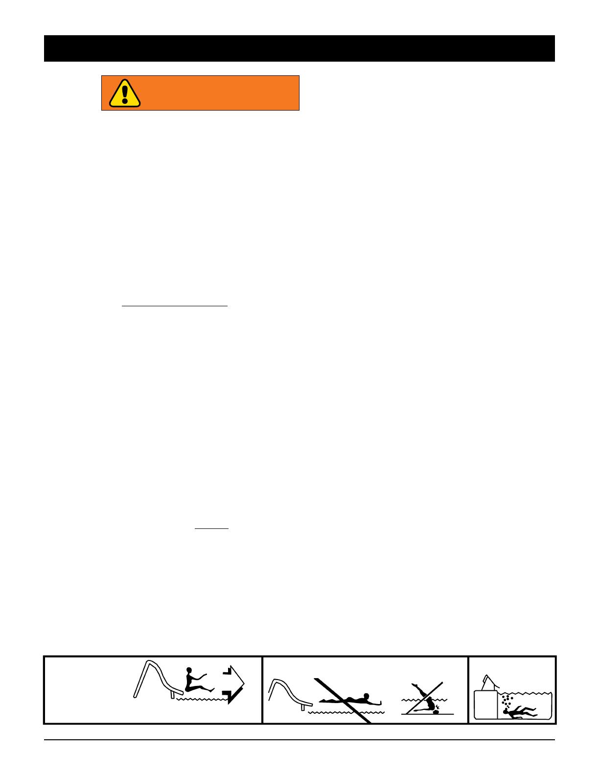
SLIDE IN A SITTING
POSITION ONLY
Face forward on the slide, holding the legs and arms with the
palms of your hands forward and tilted up.
DO NOT SLIDE HEAD FIRST SERIOUS INJURY
CAN RESULT
DEEP WATER
SWIMMERS
ONLY
INSTALLATION INSTRUCTIONS RIVER RUN SLIDE
4
SBK-RR INSTALL | 0419 Copyright ® 2019 S.R.Smith, LLC All rights reserved. | srsmith.com
DIAGRAM B
(NOT TO SCALE)
Minimum Slide
Clearance Area
13’6”
2’6”
C/L
7’
3’6”3’6”
DIAGRAM A
(NOT TO SCALE)
DIAGRAM C
(NOT TO SCALE)
Minimum Water Safety Envelope
WATER SAFETY ENVELOPE
A minimum water depth of three feet (3’) under the exit of the
slide which increases to a depth of four feet six inches (4’6”)
at point A which is located four feet six inches (4’6”) from the
back wall of the pool. A minimum depth of four feet six inches
(4’6”) must be maintained at a distance of nine feet (9’) along
the centerline of the slide from point A. The above described
water depth profile shall extend a minimum of three feet six
inches (3’6”) on either side of the centerline of the slide. (See
Diagrams A, B & C)
OR
4’6”
7’
13’6”
4’6”
4’6”
3’
20” Max
WATER SAFETY ENVELOPE
ALL SLIDES SHOULD
BE BONDED
Check your local electrical code
requirements.
INSTALLATION INSTRUCTIONS RIVER RUN SLIDE
5
SBK-RR INSTALL | 0419 Copyright ® 2019 S.R.Smith, LLC All rights reserved. | srsmith.com
SLIDE PLACEMENT
If the slide meets the pool edge at an angle, then the outside curve “Pivot A” has to be at the pool edge. Refer
to Diagram D & E below.
If the slide meets the pool edge straight on, then the end of the exit section should be parallel with the pool edge.
Refer to Diagram F below.
NOTE: The exit point of the flume can be no higher than 20” above the water.
DIAGRAM D
(NOT TO SCALE)
DIAGRAM E
(NOT TO SCALE)
DIAGRAM F
(NOT TO SCALE)
3” MINIMUM
OVERHANG
3” MINIMUM
OVERHANG
3” MINIMUM
OVERHANG
INSTALLATION INSTRUCTIONS RIVER RUN SLIDE
6
SBK-RR INSTALL | 0419 Copyright ® 2019 S.R.Smith, LLC All rights reserved. | srsmith.com
GETTING STARTED
S.R.Smith recommends that you read these instructions and helpful hints in their entirety before attempting an
installation.
IMPORTANT NOTICES:
It is highly recommended that provision be made for future removal of the slide from the substrate, if necessary.
The sizes of the concrete piers for the anchor supports specified herein are minimum measurements required
for the River Run, and may need to be increased due to local weather, soil conditions, frost line and/or local
building codes.
For best performance, the recommended water flow at the slide is 80 GPM total, 40 GPM per side.
Zoom Flume water delivery system requires a 1” PVC hose. NOTE: a ball valve in line on each side is
recommended for water flow adjustment.
Do not construct objects or formations along or over the slide pathway that obstruct the pathway for sliders
or cause potential bodily harm. Minimum recommended head clearance above the slide pathway is 7 feet.
Minimum River Run water envelope is 7’ wide (centered on slide) x 13.5’ long x 4’6” deep. (See Water Safety
Envelope - Page 4)
The exit section must be installed with the correct alignment to the pool edge and should be supported at
the fiberglass landing plate.
The surface of the slide is very slippery when wet, use caution when entering the slide. Utilization of the
provided seating assist rails is recommended for the transition from standing to sitting.
INSTALLATION INSTRUCTIONS RIVER RUN SLIDE
7
SBK-RR INSTALL | 0419 Copyright ® 2019 S.R.Smith, LLC All rights reserved. | srsmith.com
STEP 1: PREPARING SITE AREA FOR RIVER RUN SLIDE SYSTEM
First, level the hill substrate to the approximate final grade.
TIP:
The exit section should be supported at the fiberglass landing
plate. (Fig. 1) The exit plate can simply rest upon the substrate or
be drilled from the side and bolted to a bracket (not supplied).
NOTE: Build the support for the exit landing in the correct
orientation and at the correct height prior to setting the fully
assembled slide in place.
STEP 2: FLUME ASSEMBLY
Starting with the exit section, assemble the slide on the ground, right side
up along actual pathway where the slide will reside (be careful not to
scratch the slide). Attach the exit section anchor support, followed by the
next flume section in the correct order of the slide pathway. To help identify
the flume sections for the correct order of assembly, there are stickers
attached at each flange end of each flume section. For example, attach the
letter A end of the exit section to the letter A end of the next flume section
of your River Run slide. (Fig. 2 - sample only) Attach the anchor supports in
the specified locations as you build uphill and away from the pool. Stickers
are attached to the side of the flange connection that the anchor support
will connect to.
ASSEMBLY AND INSTALLATION INSTRUCTIONS
NOTE: Anchor support locations are noted on a separate sheet (included) that is specific to your exact slide design.
There are stickers attached to the correct flume piece to indicate which side of the flange you need to connect the
anchor support to.
FIG. 2
F’s
E’s
D’s
C’s
B’s
A’s
EXIT SECTION LANDING PLATE
FIG. 1
1. 3/8” Drive Ratchet
2. 3/8” x 6” Socket Extension
3. 9/16” Socket
4. 9/16” Box End Ratchet Wrench
5. Torque Wrench
6. Angle Finder
7. Tape Measure
8. 48” Level
LIST OF REQUIRED TOOLS
Tools required for assembly and installation of BYOS 2 slide:
INSTALLATION INSTRUCTIONS RIVER RUN SLIDE
8
SBK-RR INSTALL | 0419 Copyright ® 2019 S.R.Smith, LLC All rights reserved. | srsmith.com
TIPS:
Make sure to use Anti-Seize on all bolts.
Be careful not to allow dirt to get into the water delivery system on the entry section.
Gasket end of each flume section goes downhill.
The Entry Frame Support bolts to the inside of the Entry Section. There are three 3/8” bolts, one
on each side, and one in the center.
Anchor supports attach to the down slope side of the flange. (Fig. 3)
Each flange has 7 bolts (Kit BYOS2-102-SS). All bolts are 3/8” x 1-3/4”. Use Anti-Seize (in
BYOS2-101-SS) on all bolts.
Insert bolts in this order: bolt, flat washer, flanges, flat washer, lock washer, nut. On flanges that
require anchor supports insert bolts in this order: bolt, flat washer, flanges, anchor support, flat
washer, lock washer, and nut.
Insert and hand tighten all seven flange bolts. Then, utilizing a torque wrench, tighten each nut to
approximately half of the maximum 25 ft. lbs. Tighten the blots in an alternating fashion working
from left to right starting with the center bolt, working your way up the flange (Fig. 3). Repeat this
same tightening process until the specified 25 ft lbs is reached on each bolt. Do not over tighten.
Using greater force may fracture the fiberglass. Tightening the bolts in this sequence is necessary
to compress the gasket evenly.
STEP 2: FLUME ASSEMBLY - Continued
FIG. 3
1
2
3
5
7
4
6
INSTALLATION INSTRUCTIONS RIVER RUN SLIDE
9
SBK-RR INSTALL | 0419 Copyright ® 2019 S.R.Smith, LLC All rights reserved. | srsmith.com
STEP 3: ENTRY SECTION ANCHOR ASSEMBLY
Attach handrails first. Handrails are directional; the side with the 2 bends faces away from the pool. (Fig. 4)
The River Run Frame Support consists of 1 entry frame support, 1 right support arm and 1 left support arm.
The assembly is attached to the River Run Entry Section with the hardware kit BYOS2-101-SS. (Fig. 5)
Carefully turn the River Run Entry Section upside down (on cardboard) and sit the anchor upright into position
as shown. (Fig. 6 & 7)
Using 4 each 3/8”x1” bolts, attach the anchor to the entry section. Use a flat washer on each side of the part
and anchor. Pass the bolt through from the outside of part toward the underside and add a lock washer and a
nuttoeachbolt.Handtightenonly.Attachnextflumesectionafterentryand20˚anchoronthedownhillside
of assembly.
Attach right and left arms as shown. The arms are attached at this point only to the entry frame support using
2 each 3/8”x1” bolts with flat washers, lock washers and nuts. Hand tighten only. NOTE: The other end of the
rightandleftarmsattachtothe20˚anchorasshowninFig.8&9.Handtightenonly.
FIG. 7 FIG. 8 FIG. 9
FIG. 4 FIG. 5 FIG. 6
ENTRY FRAME SUPPORT
ENTRY FRAME SUPPORT
2
1
AWAY FROM POOL
INSTALLATION INSTRUCTIONS RIVER RUN SLIDE
10
SBK-RR INSTALL | 0419 Copyright ® 2019 S.R.Smith, LLC All rights reserved. | srsmith.com
FIG. 10 FIG. 11
FIG. 12 FIG. 13
STEP 3: ENTRY SECTION ANCHOR ASSEMBLY - Continued
The20˚supportmusthaveaminimumconcreteembedmentdepthof24”frombottomofanchorasshownin
Fig. 10. Anchor may be mounted in ground or with minimum 18” diameter tube.
When oriented correctly, the bottom of the entry frame support will be level as shown in Fig. 11.
The vertical portions of the support frame should be plumb (level in both axis). See Fig. 12 & 13 below.
NOTE: When slide is assembled and leveled as per instructions, the bolts on the entry support frame and anchors
may be tightened.
TIP: Once all the flume sections are assembled and the flange bolts are correctly tightened, do a water test with
a garden hose to ensure there are no flume to flume leaks.
INSTALLATION INSTRUCTIONS RIVER RUN SLIDE
11
SBK-RR INSTALL | 0419 Copyright ® 2019 S.R.Smith, LLC All rights reserved. | srsmith.com
STEP 4: 20˚ ANCHOR INFORMATION
ThefollowinginformationisfortheRiverRun20˚anchorandshouldbereviewedbeforeproceedingontothenext
step.Our20˚anchorisdesignedtoalloweasierusewithconcretetubeforms.
The length of our River Run flume anchors allow room for concrete chutes when using concrete tube forms in a
River Run installation. This anchor design will provide more flexibility in installation options and make your River Run
installations even easier. (Fig. 14)
24”
Concrete
Embedment
Depth 24”
FIG. 14
STEP 5: MOVE THE SLIDE
Once the entire slide is assembled and resting on the anchor supports in its correct horizontal position on the
pathway, use spray paint to carefully mark the location of the anchor supports. Next, with sufficient manpower,
gently move the assembled slide (if possible) approximately 3 feet to one side.
INSTALLATION INSTRUCTIONS RIVER RUN SLIDE
12
SBK-RR INSTALL | 0419 Copyright ® 2019 S.R.Smith, LLC All rights reserved. | srsmith.com
STEP 6: EXCAVATE THE HOLES
Pierholesforthe20˚flumeanchorsupportsshouldbeaminimumof12”long,24”wideand24”deep,or
minimum 18” diameter tube.
STEP 7: RESET THE RIVER RUN IN POSITION
Ensure sufficient blocking material is on hand, then utilizing sufficient manpower; lift the assembled slide back into
its correct horizontal and vertical position and block in place.
At this point, the anchor supports should be directly over, centered and within the holes for the piers or tubes,
adjust hole location as necessary at this time. The angle iron cross member will be approximately 4 below final
concrete grade for correct anchor embedment depth. (See Fig. 14) NOTE: It is essential that the vertical portions
of the anchors are plumb.
With the exception of the exit section landing plate (Fig. 1), make sure that a minimum 3 inch clearance is
maintained between any portion of the underside of the slide (including the flanges) and the substrate. Based on
the slider’s weight and velocity the slide can move slightly both vertically and horizontally. If the slide rubs upon
the substrate due to this motion a wear spot and/or leak can develop.
FIG. 15
24”
24”
12”
24”
24”
12”
ENTRY FRAME
24” x 24” x 12”
OR
18” Tube at 24” Depth
FLUME SUPPORTS
24” x 24” x 12”
OR
18” Tube at 24” Depth
The above specified sizes for the concrete piers represent a minimum
and should be increased due to local weather, soil conditions,
frost line and/or local building codes. Anchor supports shall be
bonded. Refer to your local building/electrical code requirements.
WARNING
INSTALLATION INSTRUCTIONS RIVER RUN SLIDE
13
SBK-RR INSTALL | 0419 Copyright ® 2019 S.R.Smith, LLC All rights reserved. | srsmith.com
INSTALLATION INSTRUCTIONS RIVER RUN SLIDE
STEP 8: FINAL SLIDE POSITION
It is essential that the slide be in its correct horizontal and vertical position prior to pouring concrete; and since
the pool cannot be moved, start checking position with the exit section first. Starting with and then ensuring that
the exit section is installed correctly is absolutely necessary for a successful installation.
The exit section must meet the pool edge at the correct elevation, in the correct orientation and be level in both
axes. (Fig. 16 & Fig. 17) When determining level position for the exit section please note that the exit section
startswitha20°upslope,whichthenmakesagradualtransitionto7˚theexitpoint.Checkforlevelpositiononly
as illustrated below.
Utilize an angle finder along the centerline of the flume ensure the flume is at the correct angle. Check the angle
along the centerline of the flume only. (Fig. 18) (Continued on next page)
FIG. 18
FIG. 16 FIG. 17
EXIT IS WHEN
CORRECT.
INSTALLATION INSTRUCTIONS RIVER RUN SLIDE
14
SBK-RR INSTALL | 0419 Copyright ® 2019 S.R.Smith, LLC All rights reserved. | srsmith.com
FIG. 19 FIG. 20
FIG. 21 FIG. 22
STEP 8: FINAL SLIDE POSITION - Continued
When checking for the correct flume angle keep the below in mind:
Each slide section is identified on the underside.
Theexitsectionstartsat20°ontheupslopeendwhichthenmakesagradualtransitionto7˚attheexitpoint.
The entry section seating area is almost flat, however, for proper drainage it incorporates a slight downhill
slope which transitions to a full 20°. To ensure correct placement of the entry section the entry frame
support must be level to ensure correct orientation of the slide. (Fig. 19 & 20)
The sides of the flumes should be checked for level as well. The only place along the flume where level positions
can be determined is at the flange/gasket locations. Place level across the flume at the flume joint as illustrated.
(Fig. 21 & 22) Check each flange location for level position, adjust as necessary.
TIPS FOR SETTING THE SLIDE IN FINAL POSITION:
It may take a series of adjustments to get the slide in its correct position.
At this point the entire slide should be assembled, anchor supports attached and all bolts correctly tighten.
The slide should be blocked up in its approximate horizontal and vertical position. (Continued on next page)
INSTALLATION INSTRUCTIONS RIVER RUN SLIDE
15
SBK-RR INSTALL | 0419 Copyright ® 2019 S.R.Smith, LLC All rights reserved. | srsmith.com
FIG. 23 FIG. 24
STEP 8: FINAL SLIDE POSITION - Continued
TIPS FOR SETTING THE SLIDE IN FINAL POSITION - Continued
Now, put exit section is in its correct horizontal and vertical position relative to the pool edge by adjusting
the blocks.
Then, start at the top of the slide and work down using an angle finder along the center of the flume, adjust
the blocks to achieve the correct angle for the flume.
Once the angle for the flume is set correctly, re-check the position of the exit section for alignment and height
above water, adjust as necessary.
Then, start at the top of the slide and work down, adjust the blocking materials to level the flume from side
to side.
Once the flume is level from side to side, re-check the position of exit section for alignment and height above
water, adjust as necessary.
Repeat this process until the entire slide is correctly positioned.
STEP 9: POUR CONCRETE PIERS
Once the correct horizontal and vertical position of the slide has been established and verified, pour the
concrete around anchor supports and allow to cure.
STEP 10: CONNECT WATER SUPPLY SYSTEM
The River Run slide can be plumbed with rigid 1” PVC pipe or with 1” Flex PVC, you may find that Flex PVC
works best.
Glue and slip pipe into the 1” female fittings on the underside of the Entry section. (Fig. 23 & 24) Use PVC primer
and glue (not included) as required.
The River Run has two water delivery units. A ball is valve recommended on each side to evenly adjust the water flow.
INSTALLATION INSTRUCTIONS RIVER RUN SLIDE
16
SBK-RR INSTALL | 0419 Copyright ® 2019 S.R.Smith, LLC All rights reserved. | srsmith.com
INSTALLATION INSTRUCTIONS RIVER RUN SLIDE
RIVER RUN FLUME & ANCHOR SUPPORT HARDWARE
The entry frame support anchor comes with a part specific hardware kit. Use hardware set BYOS2-101-SS.
The20˚supportanchorsallattachtoflumesectionsusingthehardwarekitBYOS2-102-SS.
ADDITIONAL ANTI-SEIZE NOTICE:
S.R.Smith adds additional anti-seize packets to BYOS1 & BYOS2 shipments, as follows:
1–5 sections: 1 packet, included in the BYOS-101-COMBO or BYOS2-101-SS kit.
6–10 sections: +1 packet, added to last section before exit*.
* River Run exits do not have hardware.
BYOS2-102-SS – FLUME TO FLUME SS HARDWARE KIT
QTY PART NUMBER COMPONENT DESCRIPTION
7 H-SS 3/8X1-34 3/8”-16X1-3/4” Hex Bolt Stainless Steel
14 H-SS 3/8 FLT WA 3/8” MS 815 Flat Washer Stainless Steel
7 H-SS 3/8 LOC WA 3/8” Lock Washer Stainless Steel
7 H-SS 3/8 F NUT 3/8”-16 Hex Nut Stainless Steel
HARDWARE NOTE:
Use a small dab of anti-seize
lubricant (included) on all
bolt threads.
FIG. 25 (BYOS2-101-SS)
Entry Section/Handrails SS Hardware Kit
FIG. 26 (BYOS2-102-SS)
Flume to Flume SS Hardware Kit
BYOS2-101-SS – ENTRY SECTION/HANDRAILS SS HARDWARE KIT
QTY PART NUMBER COMPONENT DESCRIPTION
12 H-SS 3/8X1 HB 3/8”-16X1” Hex Bolt Stainless Steel
20 H-SS 3/8 FLT WA 3/8” MS 815 Flat Washer Stainless Steel
12 H-SS 3/8 LOC WA 3/8” Lock Washer Stainless Steel
8 H-SS 3/8 F NUT 3/8” Hex Nut Stainless Steel
1 H-ANTI-SEIZE Single Use Anti-Seize Packet
INSTALLATION INSTRUCTIONS RIVER RUN SLIDE
17
SBK-RR INSTALL | 0419 Copyright ® 2019 S.R.Smith, LLC All rights reserved. | srsmith.com
RIVER RUN™ SLIDE CARE & MAINTENANCE:
Your River Run slide requires periodic maintenance to keep it looking like new and protected from the elements.
Wash slide monthly or more frequently if needed using a mild soap and soft brush cloth. Keep cleaning
materials from entering pool.
- Do not use abrasive cleaners, bleaches, chlorines, high alkaline or strong acidic cleaners.
- Do not use steel wool, wire brushes, metal scrapers, Scotchbrite or other abrasive sponge pads.
Keeping your slide’s gel coat finish coated with wax - starting when the slide is new - is the best way to
prolong its life.
- Choose a wax intended for use on gel coat surfaces. Preferably one designed for use in a Marine environment.
- Test product on small inconspicuouse section of slide prior to full application.
- While application instructions will vary between brands of wax, in general you apply the wax with a cloth
or foam pad using circular motion. Once wax dries to a haze, buff the excess with a soft dry cloth.
- Routine waxing (at least twice a year) will maintain the smooth reflective surface of your slide.
INSTALLATION INSTRUCTIONS RIVER RUN SLIDE
18
SBK-RR INSTALL | 0419 Copyright ® 2019 S.R.Smith, LLC All rights reserved. | srsmith.com
NOTES:
  • Page 1 1
  • Page 2 2
  • Page 3 3
  • Page 4 4
  • Page 5 5
  • Page 6 6
  • Page 7 7
  • Page 8 8
  • Page 9 9
  • Page 10 10
  • Page 11 11
  • Page 12 12
  • Page 13 13
  • Page 14 14
  • Page 15 15
  • Page 16 16
  • Page 17 17
  • Page 18 18
  • Page 19 19
  • Page 20 20

S R Smith River Run User manual

Category
Above ground pool accessories
Type
User manual

S R Smith River Run is a thrilling water slide designed to provide endless fun and excitement in your backyard pool. With its unique flume design, it delivers a smooth and fast ride, ensuring a memorable experience for swimmers of all ages. The slide's compact size makes it ideal for both residential and commercial pools, allowing you to transform your backyard into a personal waterpark.

Ask a question and I''ll find the answer in the document

Finding information in a document is now easier with AI