Page is loading ...

06-716
S.R. SMITH, LLC 2013
JUL13
CORPORATE HEADQUARTERS
WESTERN SALES AND MANUFACTURING PLANT
P.O. Box 400 •
••
• 1017 SW Berg Parkway
Canby, Oregon 97013
Phone: (503) 266-2231 •
••
• Fax: (503) 266-4334
www.srsmith.com
ASSEMBLY AND INSTALLATION
INSTRUCTIONS

2
Table of Contents
Topic Page #
Introduction………………………………………………………………………………………… 2
Installed Slides’ Structural & Installation Checklist…………………………………………….. 2
Parts List……………………………………………………………………………………………. 4
Assembly Instructions…………………………………………………………………………….. 5
Plumbing Instructions …………………………………………………………………………….. 13
Manufacturer’s Placement Instructions…………………………………………………………. 14
On Deck Mounting ………………………………………………………………………………... 16
Appendices A and B, Layout Details……………………………………………………………..17
INTRODUCTION
DANGER – FAILURE TO FOLLOW THESE WARNINGS, INSTRUCTIONS AND THE
OWNER’S MANUAL MAY RESULT IN SEROUS INJURY OR DEATH
THE HELIX™ SLIDE IS DESIGNED AND MANUFACTURED FOR INSTALLATION AND USE ON
INGROUND SWIMMING POOLS ONLY. DO NOT INSTALL THE HELIX SLIDE ON ABOVE GROUND
POOLS, HOUSEBOATS, BOAT DOCKS, FLOATING DOCKS OR PLATFORMS, OR OTHER BODIES
OF WATER SUCH AS LAKES, PONDS, RIVERS, ETC. PROPER ASSEMBLY, INSTALLATION, USE,
AND SUPERVISION IS ESSENTIAL FOR PROPER OPERATION AND TO REDUCE THE RISK OF
SERIOUS INJURY OR DEATH.
CHECK INSIDE ALL BOXES AND PACKAGING MATERIALS FOR PARTS. BEFORE BEGINNING
ASSEMBLY, READ ALL INSTRUCTIONS AND IDENTIFY PARTS USING THE FIGURES AND PARTS
LISTED IN THIS DOCUMENT. IT IS CRITICAL THAT ALL PARTS BE CAREFULLY INSPECTED BY
THE INSTALLER PRIOR TO INSTALLATION TO ENSURE THAT NO DAMAGE OCCURRED IN
TRANSIT AND THAT A DAMAGED PART IS NOT USED. PROPER INSTALLATION CANNOT BE
OVERSTRESSED, AS AN IMPROPER INSTALLATION VOIDS S.R. SMITH’S WARRANTY AND MAY
AFFECT THE SAFETY OF THE USER.
INSTALLER MUST GIVE TO SLIDE OWNER: HELIX SLIDE INSTALLATION AND OWNER’S
MANUAL, THE WARRANTY CARD, AND ANSWER ALL QUESTIIONS REGARDING SAFE AND
PROPER USE AND SLIDE MAINTENACE.
FOR COMPLETE SLIDE SAFETY INFORMATION REFER TO THE OWNER’S MANUAL.
INSTALLED HELIX STRUCTURAL & INSTALLATION CHECKLIST
(INSTALLER TO REVIEW WITH SLIDE OWNER UPON COMPLETION
OF SLIDE INSTALLATION)
1. INSPECT THE RUNWAY FOR VISIBLE CRACKS OR TEARS.
2. INSPECT THE SLIDE FOR SHARP EDGES, PROTRUSIONS, CRACKS OR TEARS.
3. INSPECT ALL FASTENERS TO MAKE SURE THEY ARE FULLY TIGHTENED.
4. INSPECT THE LADDER FOR RIGIDITY AND ATTACHMENT.
5. MEASURE THE FOLLOWING DIMENSIONS AND COMPARE WITH THE MANUFACTURER’S
PLACEMENT INSTRUCTIONS ON PAGES 14 AND 15.
• MEASURE THE DEPTH OF WATER IN FRONT OF THE SLIDE EXIT. (4’-6” MIN.
DEPTH AT A DISTANCE OF 4’-6” FROM EXIT END OF SLIDE.)
• MEASURE THE HEIGHT OF THE SLIDE RUNWAY EXIT ABOVE THE WATER. (20”
MAX.)
• MEASURE THE DISTANCE BETWEEN THE SLIDE CENTERLINE AND THE EDGE
OF OTHER POOL EQUIPMENT.
6. OBSERVE THE POSITION OF THE EXIT OF THE SLIDE AS SHOWN IN FIGURES 15, 16 AND
18 ON PAGES 14 AND 15.

3
SEE APPENDICES A and B (pg.17) for additional slide layout
details.
Figure 1

4
HELIX™ PARTS LIST
ITEM #
PART #
DESCRIPTION
QTY.
1 5-139 3/8” Hex Nut 9 ea.
2 5-151 3/8” Lock Washer 11 ea.
3 05-14-115 1/2" Lock Washer 8 ea.
4 5-145 3/8” Flat Washer 25 ea.
5 5-246 3/8” x 2-3/4” Carriage Bolt 2 ea.
6 5-247 3/8” x 3” Button Head Cap Screw 4 ea.
7 5-239 3/8” x 2-1/2” Stud 4 ea.
8 5-240 3/8” x 3-1/2” Lag Screw 6 ea.
9 5-237 3/8” x 5” Button Head Cap Screw 2 ea.
10 5-248 3/8” x 3.5” Hex Head Cap Screw 2 ea.
11 5-242 #14" x 1” Pan Head Tapping Screw 6 ea.
12 5-241 1/2" x 5” Anchor Stud 8 ea.
13 5-643 3/8”-16 x 2 Hex Head Tap Bolt 1 ea.
14 05-782 1.5” PVC Pipe Strap 2 ea.
15 05-767 1” Pipe Clamp 2 ea.
16 05-770 1” Ball Valve Gray 1 ea.
17 05-784 1” Coupling 1 ea.
18 05-773 Garden Hose Adapter 1 ea.
19 8-532 .5" HIGH X .5” WIDE X 32” LONG RUBBER GASKET 1 ea.
20 05-643 Dark Gray PVC, 1” Slip Pipe Fitting, Female Tee ,SCH80 1 ea.
21 05-660 D.G. 1” PVC Slip Reducer to ½” Threaded Female, SCH 80 1 ea.
22 05-667 3/8” to1/2” barbed 90° elbow fitting 1 ea
23 05-786-1
1” PVC Flex Hose, 16” long
(Not Shown)
1 ea.
24 05-786-2
1” PVC Flex Hose, 68” long
(Not Shown)
1 ea.
25 05-661
1” PVC Pipe x
2
” L
ong
(Not Shown)
1 ea.
26 5-156 3/8” Acorn Nut 1 ea.
27 05-040-2
1/2" OD X 3/8" ID Polypropylene
Tubing (23")
(Not Shown)
1 ea.
(1)
(2)
(3)
(5)
(6)
(7)
(8)
(9)
(10)
(1
6
)
(12)
(1
4
)
(4)
(11)
(
1
8
)
(1
5
)
(
19
)
(17)
(13)
(20
)
(
21
)
(22
)
(26)
Figure 2

5
ASSEMBLY INSTRUCTIONS
Tools Required:
1. Ratchet handle
2. 9/16” deep socket
3. 9/16” wrench
4. 5/8” wrench
5. 3/4" socket or wrench
6. 7/32” allen wrench
7. Phillips head screwdriver
8. 1/2" concrete drill bit
9. 1/4" drill bit
10. Power drill
11. PVC pipe primer & glue
12. Anti-seize
13. Saw to cut PVC pipe
14. Knife
15. Level
16. Teflon tape (plumbers tape)
17. Silicone sealant
Gasket Installation:
• Most of the gasket material has been installed at the factory, however additional gasket has been provided
in case any gasket has fallen off during shipping. If gasket installation is required, follow the instructions
below. The gasket on the face of the ladder is not installed in the factory, but detailed instructions are
provided in step 8 on page 8.
• Apply gasket (PN 8-532) in the required locations as shown in the figures below.
• Place gasket along the section to determine the length needed.
• Cut gasket to appropriate length, within the width of the runway only, do not include the shoulder.
• Remove backing and adhere gasket to slide.
• All gaskets below are applied as shown in the gasket section detail (see step 8 for further details
on installing the ladder gasket, PN 8-531)
.5” X .5”
GASKET
.5” X .5”
GASKET
Figure
3

6
Assembly:
Before getting started:
• To prevent damage to the parts during assembly, it is recommended that cardboard or
some other protective barrier is laid down on the ground where the slide is to be
assembled.
• Verify that the gasket material is affixed to the slide parts as shown on page 4
• During assembly, be sure to apply a thin coat of anti-seize compound to the threads of all
fasteners. Anti-seize helps aid in assembly, prevents galling, and improves corrosion
resistance.
1) Attach the pedestal part to the runway exit section as shown in Figure 4 by inserting the two lag
screws into the holes located in the bottom of the pedestal.
2) Before inserting the lag bolts into the side of the runway exit part, 1/4” pilot holes must be drilled into
the center of each of the recesses, each location is marked with a dimple showing where to drill. The
pilot holes should be drilled through both the runway exit section and into the pedestal.
3) Place the assembled runway exit section and pedestal upright so that the pedestal is resting on the
ground. Notes: It may take more than one person to perform this step. Verify that the gasket
material is properly attached before assembling the parts.
Figure 4
(
4
)
(8)

7
4) Insert the threaded studs into each of the threaded inserts as shown in Figure 5. The studs should be
screwed in by hand until they reach the bottom of the insert. If the studs cannot be threaded in by
hand, pliers may be used. Before using pliers, a piece of cloth should be placed over the stud to
protect the threads from damage. Note: Be sure to apply anti-seize to all fasteners to prevent
galling.
5) Assemble the top ladder section and lower ladder section as shown in Figure 6. Insert the two button
head cap screws into the threaded inserts as shown in Figure 6. Do not fully tighten the screws at this
point; start the screws into the threaded inserts. Note: Be sure to apply anti-seize to all fasteners
to prevent galling.
6) Insert the button head cap screws into the back side of the ladder as shown in Figure 7. Tighten the
screws until snug. Go back and fully tighten the screws from Step 5. Note: Be sure to apply anti-seize
to all fasteners to prevent galling.
7) Insert the two carriage bolts into the steps as shown in Figure 6. Tighten the nuts onto the carriage
bolt until the lock washer is fully compressed. Note: Be sure to apply anti-seize to all fasteners to
prevent galling.
Figure 5
(
7
)
Figure 6
(2)
(1)
(4)
(6)
(4)
(5)

8
8) Before applying the gasket to the top of the ladder, be sure that the joint surfaces of the top
runway and ladder sections are clean and dry. Unroll the gasket material and hold so that length
of the gasket is centered on the center of the ladder joint. With the exposed adhesive side of the
gasket facing the ladder joint surface, apply the gasket starting at the center of the part, working
outward to the sides. Be sure that the bottom edge of the gasket material is held against the
shelf on the ladder part during installation, see reference images below. Do not make too tight of
a bend radius with the gasket when transitioning the gasket up the vertical edges of the joint. The
transition radius should be as large as possible. Making too tight of a bend radius will cause the
gasket to kink and possibly leak. The gasket should be centered on the available space in the
vertical area of the joint, see reference images below. Once the gasket is in place, firmly press
down on the gasket in all locations to ensure that the gasket has completely adhered to the
ladder joint surface. Remove the paper backing on the outward face of the gasket to expose the
adhesive. Use caution not to remove the adhesive strip from the gasket when removing the
paper backing.
Figure 7
(6)
(4)
GASKET

9
9) Lay the ladder assembly on the ground with the steps facing down as shown in Figure 8. Lift
the upper runway section and align the threaded studs sticking out of the top ladder section
with the holes in the upper runway section. Attach the runway to the ladder using the
hardware shown in Figure 8. Tighten until the lock washer is fully compressed. Notes: It
may take more than one person to perform this step. Verify that the gasket material is
properly attached before assembling the parts. Be sure to apply anti-seize to all
fasteners to prevent galling.
10) Apply a .25 inch bead of Silicone sealant (Silicone II or similar) around the base of the cone
of the slide’s center column. See Figure 9.
(4)
(1) (2)
F
igure
8
APPLY .25” BEAD OF SILICONE
Figure 9

10
(
2
)
(
4
)
(
9
)
(26)
11) Stand the ladder upright and attach the runway entrance section to the runway exit section
using the button head cap screw as shown in Figure 10 through the slides center column. Do
not tighten the bolt at this point. Notes: It may take more than one person to perform this
step. Be sure to apply anti-seize to all fasteners to prevent galling.
12) Finish assembling the two runway sections using the hardware shown in Figure 11. Note:
Be sure to apply anti-seize to all fasteners to prevent galling.
a. First, the 2” Hex Head Tap Bolt (Item 13) should started into the threaded insert; do not
tighten at this point.
b. Install the 5” Button Head screw (Item 9) into the outside rail, and fully tighten.
c. Install the hex bolts (Items 10) through the underside of the run way.
d. Go through and tighten all of the hardware installed in steps 11and 12.
Figure 10

11
13) Attach the two 1” Pipe Clamps (15) with the #14 Pan Head Screws (11) as shown in Figure
12, Detail B. in the recessed area under the slide ladder.
14) Fully assemble the water system components as shown in Figure 12 Detail A without glue to
ensure that all components have the correct fit and function before permanently gluing them
together.
a. The PVC 1” Slip Pipe “T” Fitting, Female (20) located directly below the 1” Ball Valve (16)
must be slightly rotated to the right with respect to the handle of the 1”Ball Valve (16), as
shown in Figure 12 Detail C.
b. With the plumbing assembled as shown in Figure 12 Detail C, ensure that the ½”
Polypropylene Tubing (27) is routed behind the 1” PVC Flex Hose (23) in the recessed
area of the ladder and does not interfere with movement of the handle on the 1”Ball Valve
(16).
c With the components oriented in the correct position, make reference marks on the 1”
Ball Valve (16), 1” PVC Slip Pipe “T” Fitting, Female (20) and 1” PVC Pipe 2” long (25) to
ensure correct orientation before gluing.
d When attaching the assembled components with 1.5” Pipe Strap (14) to the slide ensure
that the ½” Polypropylene Tubing (27) is routed behind 1” PVC Flex Hose (23).
15) Once the plumbing fit and function has been verified, remove the plumbing components from
the ladder in preparation for final gluing and assembly.
16) Use PVC primer and glue to permanently assemble the parts together as described in Step
14 and shown in Figure 12. Ensure that The 1 “PVC Slip Pipe “T” Fitting, Female (20), 1”
(13)
(2)
(4)
(1)
(2)
(4)
(4)
(2)
(1)
(4)
(2)
(1)
(10)
(4)
(10)
(4)
(9)
Figure 11

12
PVC Pipe 2” long (25) and 1” Ball Valve (16) are completely fit together and reference marks
are aligned per instruction #14 b.
17) Use plumbers tape (Teflon tape) when permanently assembling the 3/8” to1/2” barbed 90°
elbow fitting (22) to the 1” PVC Slip Reducer to ½” Threaded Female (21).
18) Glue the top end of the 1” PVC Flex Hose 16” long (23) into the fitting in the ladder.
19) Route the ½” Polypropylene Tubing (27) behind the 1” PVC Flex Hose 16” long (23) as
shown in Figure 12 Detail C. Connect the ½” Polypropylene Tubing (27) to the small ball
valve attached to the top runway section by pushing the ½” Polypropylene Tubing (27) into
the end of the ball valve firmly as far as it will go. See Figure 13.
20) Secure the assemblies to the recessed area under the slide ladder by attaching the 1.5” PVC
Pipe Straps (14) with the #14 Pan Head Screws (11). See Figure 12 Detail A..
21) Secure the 1” PVC Flex Hose 68” long (24) in the hose recess under the ladder using the 1”
pipe Clamp (15) firmly pushing the 1” PVC Flex Hose 68” (24) into the 1” pipe Clamp (15).
(15)
(11)
Fig.
1
2
(25)
(24)
(23)
(20)
(21) (22)
(11)
(14)
(16)
(27)
GLUE TO FITTING
IN LADDER (Step 18)
DETAIL C
(20)
(22)
(16)
(27)
PUSH INTO SMALL
BALL VALVE (Step 19)

13
Fig.
1
4
(18)
(17)
(24)
PLUMBING INSTRUCTIONS
1. The helix™ is designed for a water supply line of 1” pipe.
Plumb from pool return line with a 1” PVC pipe “stubbed up”
at the deck positioned at the base of the ladder. Refer to
Figure 1 on page 2. Figure 1 is for reference only.
Assembled slide should be placed in its correct location and
the “stub up” location marked and installed before mounting
the slide to the deck. “Stub up” should be dark grey PVC to
match the plumbing assembly of the slide. Note: “Stub up”
should extend above the deck 18” in height; it will be cut
down later in the installation process.
2. If a garden hose is to be used, a garden hose adapter fitting
is included with the slide. Assemble the pieces as shown in
Figure 14 and attach to the end of the PVC plumbing
assembly at the base of the ladder.
3. Proceed to the following section for ON-DECK MOUNTING.
After the slide has been mounted to the deck, attach the
“stub up” to the plumbing assembly installed in the ladder.
4. The helix™ can handle up to 20 gallons per minute. Water
flow to the main water supply is to be regulated using the ball
valve (16) near the center of the ladder. The fountain feature
can be regulated via the small ball valve just under the top of the ladder. Figure 13 shows the
location of the small ball valve.
5. The fountain feature and the main water supply can be either used together or alone.
a. To use only the main water supply, shut off the small ball valve. Adjust the large ball valve
for the desired water flow.
b. To use only the fountain, shut off the large ball valve. Adjust the small ball valve for desired
flow.
c. To use both the fountain and the main water supply together, the large ball valve must be
partially closed. In general, closing the large ball valve more will increase the flow to the
fountain. Adjust the small and large ball valves to obtain the desired flow from each water
feature.
BROKEN OUT
SECTION
DETAIL A
Fig. 1
3
SMALL BALL VALVE

14
Figure 16
MANUFACTURER’S PLACEMENT INSTRUCTIONS
PROPER ASSEMBLY, INSTALLATION, USE, AND SUPERVISION IS ESSENTIAL FOR PROPER
OPERATION AND TO REDUCE THE RISK OF SERIOUS INJURY OR DEATH.
1. The critical dimensions for placement of the Helix are as shown in Figures 15 and 16.
A. The slide exit runway surface shall not exceed twenty inches (20”) above the water surface as
shown in Figure 15.
B. The slide shall be positioned so that all water flowing off the runway exit drops into the pool. The
recommended overhang is 4 inches.
C. The minimum depth of water below the exit lip of the slide shall be three feet (3’) and increase to
four feet six inches (4’-6”) at Pt. A, which is a distance of four feet six inches (4’-6”) from the exit
lip of the slide as shown in Figure 15.
D. A minimum depth of four feet six inches (4’-6”) shall be maintained at a distance of nine feet (9’)
along the extended centerline of the slide from Pt. A. as shown in Figure 15.
2. A minimum clearance area in front of the slide shall be maintained at all times as
follows:
The minimum clearance distance on either side of the extended centerline of the
slide runway shall not be less than three feet six inches (3’-6”) at a point no less
than two feet six inches (2’-6”) from the exit lip of the slide and extending a distance
of thirteen feet six inches (13’-6”) in front of the slide as shown in Figure 16.
DECK/COPING SURFACE
3' MIN.
EXIT
RUNWAY SURFACE
PLUMBLINE
20" MAX.
WATER LEVEL
ENTRANCE
Pt.A
13'-6" MIN.
9' MIN. 4'-6"
4'-6" MIN.4'-6" MIN.
F
igure
1
5
SLIDE MINIMUM CLEARANCE AREA
3'-6"
C
L
2'-6"
13'-6"
3'-6"
EXTENDED CENTERLINE

15
3. SLIDE PLACEMENT INSTRUCTIONS FOR INSTALLATIONS ON POOLS WITH OTHER SLIDES
AND/OR DIVING BOARDS
A. The minimum clearance area in front of a properly installed diving board on an inground
swimming pool is a minimum distance of three feet six inches (3’-6”) on either side of the board’s
centerline as shown in Figure 17. Pt. C extends a minimum distance of “C” from the tip end of the
board as shown in Figure 17. The width distance “W” on either side of Pt. C is given in CHART 1
and shown in Figure 17.
“C”
DIMENSION FOR BOARD
= AB + BC
“W”
DIMENSION FOR BOARD
= WIDTH AT PT.C
B. The minimum clearance area of a slide or diving board shall not intersect any coping or rope and
float line as shown in Figure 18. The minimum clearance area of a slide or diving board may
intersect each other provided that they are not used simultaneously.
CHART 1
BOARD MINIMUM CLEARANCE AREA
POOL TYPE
“C” DIMENSION “W” DIMENSION
I 14’-6” 5’-0”
II 14’-6” 6’-0”
III 16’-6” 6’-0”
IV 18’-6” 7’-6”
V 21’-0” 7’-6”
See Article 5 contained in ANSI/APSP/ICC-5 2011
STANDARD FOR RESIDENTIAL INGROUND SWIMMING
POOLS and refer to FIGURE 3 and Table 1 for Minimum
Water Envelope Dimensions AB, BC and Width at Point C.
Figure
1
8
Figure
1
7

16
ON-DECK MOUNTING INSTRUCTIONS
1. Place the assembled slide on the deck relative to the pool wall. Ensure
that the exit flume clears any coping. Slide may be angled slightly
providing all dimensions are maintained as noted in the Manufacturer’s
Placement Instructions noted in the following section.
2. With the slide in its proper location, center punch or otherwise mark
through the (8) mounting holes at the bottom of the ladder and pedestal
so that a visible mark is apparent on the concrete.
3. Move the assembled slide aside to facilitate drilling of the anchoring
holes.
4. Using a power drill and a 1/2” concrete drill bit, drill the holes to a depth
of 4”. Use tape or a marking on the drill bit to ensure that the hole for the
anchor is drilled to the required depth. Maintain drill hole straight and
perpendicular for proper holding strength of anchor stud.
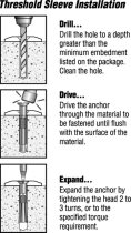
5. Clear the holes of all debris. Assemble anchor with nut and washer so
that the top of the nut is flush with the top of the anchor. Move the slide
over the holes before inserting the anchors. Drive anchor through
the slide mounting holes so that nut and washer are flush with the
surface material.
6. Expand anchor by tightening nut 3 to 5 turns. Once anchor is set remove
nut and install a lock washer, item # (3), and retighten nut to a torque of
25 ft.-lbs.

17
APPENDIX A

18
APPENDIX B
/


