Mitsubishi Electric MR-J2S-CT4 Series User manual
- Category
- PC/workstation barebones
- Type
- User manual


MELDAS is a registered trademark of Mitsubishi Electric Corporation.
Other company and product names that appear in this manual are trademarks or
registered trademarks of their respective companies.


Introduction
Thank you for selecting the Mitsubishi numerical control unit.
This instruction manual describes the handling and caution points for using this AC
servo/spindle.
Incorrect handling may lead to unforeseen accidents, so always read this instruction
manual thoroughly to ensure correct usage.
Make sure that this instruction manual is delivered to the end user.
Always store this manual in a safe place.
In order to confirm if all function specifications described in this manual are applicable,
refer to the specifications for each CNC.
Notes on Reading This Manual
(1) Since the description of this specification manual deals with NC in general, for the
specifications of individual machine tools, refer to the manuals issued by the
respective machine manufacturers. The "restrictions" and "available functions"
described in the manuals issued by the machine manufacturers have precedence to
those in this manual.
(2) This manual describes as many special operations as possible, but it should be kept
in mind that items not mentioned in this manual cannot be performed.


Precautions for safety
Please read this manual and auxiliary documents before starting installation, operation,
maintenance or inspection to ensure correct usage. Thoroughly understand the device, safety
information and precautions before starting operation.
The safety precautions in this instruction manual are ranked as "WARNING" and "CAUTION".
DANGER
When there is a potential risk of fatal or serious injuries if
handling is mistaken.
WARNING
When a dangerous situation, or fatal or serious injuries may
occur if handling is mistaken.
CAUTION
When a dangerous situation may occur if handling is mistaken
leading to medium or minor injuries, or physical damage.
Note that some items described as
CAUTION
may lead to major results depending on
the situation. In any case, important information that must be observed is described.
The signs indicating prohibited and mandatory matters are explained below.
Indicates a prohibited matter. For example, "Fire Prohibited"
is indicated as .
Indicates a mandatory matter. For example, grounding is
indicated as .
After reading this specifications and instructions manual, store it where the user can access it
easily for reference.
The numeric control unit is configured of the control unit, operation board, servo drive unit,
spindle drive unit, power supply, servomotor and spindle motor, etc.
In this section "Precautions for safety", the following items are generically called the "motor".
• Servomotor
• Linear servomotor
• Spindle motor
In this section "Precautions for safety", the following items are generically called the "unit".
• Servo drive unit
• Spindle drive unit
• Power supply unit
• Scale interface unit
• Magnetic pole detection unit
POINT
Important matters that should be understood for operation of this machine
are indicated as a POINT in this manual.

WARNING
1. Electric shock prevention
Do not open the front cover while the power is ON or during operation. Failure to observe this
could lead to electric shocks.
Do not operate the unit with the front cover removed. The high voltage terminals and charged
sections will be exposed, and can cause electric shocks.
Do not remove the front cover and connector even when the power is OFF unless carrying
out wiring work or periodic inspections. The inside of the units is charged, and can cause
electric shocks.
Since the high voltage is supplied to the main circuit connector while the power is ON or
during operation, do not touch the main circuit connector with an adjustment screwdriver or
the pen tip. Failure to observe this could lead to electric shocks.
Wait at least 15 minutes after turning the power OFF, confirm that the CHARGE lamp has
gone out, and check the voltage between P and N terminals with a tester, etc., before starting
wiring, maintenance or inspections. Failure to observe this could lead to electric shocks.
Ground the unit and motor following the standards set forth by each country.
Wiring, maintenance and inspection work must be done by a qualified technician.
Wire the servo drive unit and servomotor after installation. Failure to observe this could lead to
electric shocks.
Do not touch the switches with wet hands. Failure to observe this could lead to electric shocks.
Do not damage, apply forcible stress, place heavy items on the cables or get them caught.
Failure to observe this could lead to electric shocks.
2. Injury prevention
The linear servomotor uses a powerful magnet on the secondary side, and could adversely
affect pacemakers, etc.
During installation and operation of the machine, do not place portable items that could
malfunction or fail due to the influence of the linear servomotor's magnetic force.
Take special care not to pinch fingers, etc., when installing (and unpacking) the linear
servomotor.
In the system where the optical communication with CNC is executed, do not see directly the
light generated from CN1A/CN1B connector of drive unit or the end of cable. When the light
gets into eye, you may feel something is wrong for eye.
(The light source of optical communication corresponds to class1 defined in JISC6802 or
IEC60825-1.)

CAUTION
1. Fire prevention
Install the units, motors and regenerative resistor on non-combustible material. Direct
installation on combustible material or near combustible materials could lead to fires.
Always install a circuit protector and contactor on the servo drive unit power input as explained
in this manual. Refer to this manual and select the correct circuit protector and contactor. An
incorrect selection could result in fire.
Shut off the power on the unit side if a fault occurs in the units. Fires could be caused if a large
current continues to flow.
When using a regenerative resistor, provide a sequence that shuts off the power with the
regenerative resistor's error signal. The regenerative resistor could abnormally overheat and
cause a fire due to a fault in the regenerative transistor, etc.
The battery unit could heat up, ignite or rupture if submerged in water, or if the poles are
incorrectly wired.
Cut off the main circuit power with the contactor when an alarm or emergency stop occurs.
2. Injury prevention
Do not apply a voltage other than that specified in this manual, on each terminal. Failure to
observe this item could lead to ruptures or damage, etc.
Do not mistake the terminal connections. Failure to observe this item could lead to ruptures or
damage, etc.
Do not mistake the polarity (
+
,
–
). Failure to observe this item could lead to ruptures or
damage, etc.
Do not touch the radiation fin on unit back face, regenerative resistor or motor, etc., or place
parts (cables, etc.) while the power is turned ON or immediately after turning the power OFF.
These parts may reach high temperatures, and can cause burns or part damage.
Structure the cooling fan on the unit back face, etc., etc so that it cannot be touched after
installation. Touching the cooling fan during operation could lead to injuries.

CAUTION
3. Various precautions
Observe the following precautions. Incorrect handling of the unit could lead to faults, injuries and
electric shocks, etc.
(1) Transportation and installation
Correctly transport the product according to its weight.
Use the motor's hanging bolts only when transporting the motor. Do not transport the
machine when the motor is installed on the machine.
Do not stack the products above the tolerable number.
Follow this manual and install the unit or motor in a place where the weight can be borne.
Do not get on top of or place heavy objects on the unit.
Do not hold the cables, axis or detector when transporting the motor.
Do not hold the connected wires or cables when transporting the units.
Do not hold the front cover when transporting the unit. The unit could drop.
Always observe the installation directions of the units or motors.
Secure the specified distance between the units and control panel, or between the servo drive
unit and other devices.
Do not install or run a unit or motor that is damaged or missing parts.
Do not block the intake or exhaust ports of the motor provided with a cooling fan.
Do not let foreign objects enter the units or motors. In particular, if conductive objects such as
screws or metal chips, etc., or combustible materials such as oil enter, rupture or breakage
could occur.
The units and motors are precision devices, so do not drop them or apply strong impacts to
them.

CAUTION
Store and use the units under the following environment conditions.
Environment
Unit Motor
Ambient
temperature
Operation: 0 to 55°C (with no freezing),
Storage / Transportation: -15°C to 70°C
(with no freezing)
Operation: 0 to 40°C (with no freezing),
Storage: -15°C to 70°C
(Note 2)
(with no freezing)
Ambient
humidity
Operation: 90%RH or less
(with no dew condensation)
Storage / Transportation: 90%RH or less
(with no dew condensation)
Operation: 80%RH or less
(with no dew condensation),
Storage: 90%RH or less
(with no dew condensation)
Atmosphere
Indoors (no direct sunlight)
With no corrosive gas, inflammable gas, oil mist, dust or conductive fine particles
Altitude
Operation/Storage: 1000 meters or less above
sea level,
Transportation: 13000 meters or less above sea
level
Operation: 1000 meters or less above sea level,
Storage: 10000 meters or less above sea level
Vibration/impact
According to each unit or motor specification
(Note 1) For details, confirm each unit or motor specifications in addition.
(Note 2) -15°C to 55°C for linear servomotor.
Securely fix the servomotor to the machine. Insufficient fixing could lead to the servomotor
slipping off during operation.
Always install the servomotor with reduction gear in the designated direction. Failure to do so
could lead to oil leaks.
Structure the rotary sections of the motor so that it can never be touched during operation.
Install a cover, etc., on the shaft.
When installing a coupling to a servomotor shaft end, do not apply an impact by hammering,
etc. The detector could be damaged.
Do not apply a load exceeding the tolerable load onto the servomotor shaft. The shaft could
break.
Store the motor in the package box.
When inserting the shaft into the built-in IPM motor, do not heat the rotor higher than 130°C.
The magnet could be demagnetized, and the specifications characteristics will not be
ensured.
Always use a nonmagnetic tool (explosion-proof beryllium copper alloy safety tool: NGK
Insulators, etc.) when installing the linear servomotor.
Always provide a mechanical stopper on the end of the linear servomotor's travel path.
If the unit has been stored for a long time, always check the operation before starting actual
operation. Please contact the Service Center, Service Station, Sales Office or delayer.

CAUTION
(2) Wiring
Correctly and securely perform the wiring. Failure to do so could lead to abnormal operation of
the motor.
Do not install a condensing capacitor, surge absorber or radio noise filter on the output side of
the drive unit.
Correctly connect the output side of the drive unit (terminals U, V, W). Failure to do so could
lead to abnormal operation of the motor.
When using a power regenerative power supply unit, always install an AC reactor for each
power supply unit.
In the main circuit power supply side of the unit, always install an appropriate circuit protector
or contactor for each unit. Circuit protector or contactor cannot be shared by several units.
Always connect the motor to the drive unit's output terminals (U, V, W).
Do not directly connect a commercial power supply to the servomotor. Failure to observe this
could result in a fault.
When using an inductive load such as a relay, always connect a diode as a noise measure
parallel to the load.
When using a capacitance load such as a lamp, always connect a protective resistor as a noise
measure serial to the load.
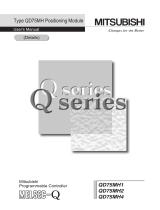
Do not reverse the direction of a diode
which connect to a DC relay for the
control output signals such as
contractor and motor brake output, etc.
to suppress a surge. Connecting it
backwards could cause the drive unit to
malfunction so that signals are not
output, and emergency stop and other
safety circuits are inoperable.
COM
(24VDC)
Control output
signal
Servodrive unit
RA
COM
(24VDC)
Servodrive unit
RA
Control output
signal
Do not connect/disconnect the cables connected between the units while the power is ON.
Securely tighten the cable connector fixing screw or fixing mechanism. An insecure fixing could
cause the cable to fall off while the power is ON.
When using a shielded cable instructed in the instruction manual, always ground the cable with
a cable clamp, etc.
Always separate the signals wires from the drive wire and power line.
Use wires and cables that have a wire diameter, heat resistance and flexibility that conforms to
the system.

CAUTION
(3) Trial operation and adjustment
Check and adjust each program and parameter before starting operation. Failure to do so could
lead to unforeseen operation of the machine.
Do not make remarkable adjustments and changes of parameter as the operation could
become unstable.
The usable motor and unit combination is predetermined. Always check the models before
starting trial operation.
If the axis is unbalanced due to gravity, etc., balance the axis using a counterbalance, etc.
The linear servomotor does not have a stopping device such as magnetic brakes. Install a
stopping device on the machine side.
(4) Usage methods
In abnormal state, install an external emergency stop circuit so that the operation can be
stopped and power shut off immediately.
Turn the power OFF immediately if smoke, abnormal noise or odors are generated from the unit
or motor.
Do not disassemble or repair this product.
Never make modifications.
When an alarm occurs, the machine will start suddenly if an alarm reset (RST) is carried out
while an operation start signal (ST) is being input. Always confirm that the operation signal is
OFF before carrying out an alarm reset. Failure to do so could lead to accidents or injuries.
Reduce magnetic damage by installing a noise filter. The electronic devices used near the
unit could be affected by magnetic noise. Install a line noise filter, etc., if there is a risk of
magnetic noise.
Use the unit, motor and regenerative resistor with the designated combination. Failure to do so
could lead to fires or trouble.
The brake (magnetic brake) of the servomotor are for holding, and must not be used for normal
braking.
There may be cases when holding is not possible due to the magnetic brake's life, the machine
construction (when ball screw and servomotor are coupled via a timing belt, etc.) or the
magnetic brake’s failure. Install a stop device to ensure safety on the machine side.
After changing the programs/parameters or after maintenance and inspection, always test the
operation before starting actual operation.
Do not enter the movable range of the machine during automatic operation. Never place body
parts near or touch the spindle during rotation.
Follow the power supply specification conditions given in each specification for the power (input
voltage, input frequency, tolerable sudden power failure time, etc.).
Set all bits to "0" if they are indicated as not used or empty in the explanation on the bits.
Do not use the dynamic brakes except during the emergency stop. Continued use of the
dynamic brakes could result in brake damage.
If a circuit protector for the main circuit power supply is shared by several units, the circuit
protector may not activate when a short-circuit fault occurs in a small capacity unit. This is
dangerous, so never share the circuit protector.

CAUTION
(5) Troubleshooting
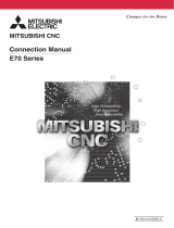
If a hazardous situation is predicted during power failure or product trouble, use a servomotor
with magnetic brakes or install an external brake mechanism.
Use a double circuit configuration
that allows the operation circuit for
the magnetic brakes to be operated
even by the external emergency
stop signal.
MBR
24VDC
EMG
Magnetic
brake
Servomotor
Shut off with the servomotor
brake control output.
Shut off with NC brake
control PLC output.
Always turn the input power OFF when an alarm occurs.
If an alarm occurs, remove the cause, and secure the safety before resetting the alarm.
Never go near the machine after restoring the power after a power failure, as the machine
could start suddenly. (Design the machine so that personal safety can be ensured even if the
machine starts suddenly.)
(6) Maintenance, inspection and part replacement
Always backup the programs and parameters before starting maintenance or inspections.
The capacity of the electrolytic capacitor will drop over time due to self-discharging, etc. To
prevent secondary disasters due to failures, replacing this part every five years when used
under a normal environment is recommended. Contact the Service Center, Service Station,
Sales Office or delayer for repairs or part replacement.
Do not perform a megger test (insulation resistance measurement) during inspections.
If the battery low warning is issued, back up the machining programs, tool data and
parameters with an input/output unit, and then replace the battery.
Do not short circuit, charge, overheat, incinerate or disassemble the battery.
The heat radiating fin used in some units contains substitute Freon as the refrigerant.Take
care not to damage the heat radiating fin during maintenance and replacement work.
(7) Disposal
Do not dispose of this type of unit as general industrial waste. Always contact the Service
Center, Service Station, Sales Office or delayer for repairs or part replacement.
Do not disassemble the unit or motor.
Dispose of the battery according to local laws.
Always return the secondary side (magnet side) of the linear servomotor to the Service
Center or Service Station.
When incinerating optical communication cable, hydrogen fluoride gas or hydrogen chloride
gas which is corrosive and harmful may be generated. For disposal of optical communication
cable, request for specialized industrial waste disposal services that has incineration facility
for disposing hydrogen fluoride gas or hydrogen chloride gas.

CAUTION
(8) Transportation
The unit and motor are precision parts and must be handled carefully.
According to a United Nations Advisory, the battery unit and battery must be transported
according to the rules set forth by the International Civil Aviation Organization (ICAO),
International Air Transportation Association (IATA), International Maritime Organization
(IMO), and United States Department of Transportation (DOT), etc.
(9) General precautions
The drawings given in this manual show the covers and safety partitions, etc., removed to provide a
clearer explanation. Always return the covers or partitions to their respective places before starting
operation, and always follow the instructions given in this manual.

{ Treatment of waste {
The following two laws will apply when disposing of this product. Considerations must be made to each
law. The following laws are in effect in Japan. Thus, when using this product overseas, the local laws will
have a priority. If necessary, indicate or notify these laws to the final user of the product.
1. Requirements for "Law for Promotion of Effective Utilization of Resources"
(1) Recycle as much of this product as possible when finished with use.
(2) When recycling, often parts are sorted into steel scraps and electric parts, etc., and sold to scrap
contractors. Mitsubishi recommends sorting the product and selling the members to appropriate
contractors.
2. Requirements for "Law for Treatment of Waste and Cleaning"
(1) Mitsubishi recommends recycling and selling the product when no longer needed according to
item (1) above. The user should make an effort to reduce waste in this manner.
(2) When disposing a product that cannot be resold, it shall be treated as a waste product.
(3) The treatment of industrial waste must be commissioned to a licensed industrial waste treatment
contractor, and appropriate measures, including a manifest control, must be taken.
(4) Batteries correspond to "primary batteries", and must be disposed of according to local disposal
laws.

Compliance to European EC Directives
1. European EC Directives
The European EC Directives were issued to unify Standards within the EU Community and to smooth
the distribution of products of which the safety is guaranteed. In the EU Community, the attachment of
a CE mark (CE marking) to the product being sold is mandatory to indicate that the basic safety
conditions of the Machine Directives (issued Jan. 1995), EMC Directives (issued Jan. 1996) and the
Low-voltage Directives (issued Jan. 1997) are satisfied. The machines and devices in which the servo
is assembled are a target for CE marking.
The servo is a component designed not to function as a single unit but to be used with a combination
of machines and devices. Thus, it is not subject to the EMC Directives, and instead the machines and
devices in which the servo is assembled are targeted.
This servo complies with the Standards related to the Low-voltage Directives in order to make CE
marking of the assembled machines and devices easier. The EMC INSTALLATION GUIDELINES (IB
(NA) 67303) which explain the servo drive unit installation method and control panel manufacturing
method, etc., has been prepared to make compliance to the EMC Directives easier. Contact
Mitsubishi or your dealer for more information.
2. Cautions of compliance
Use the standard servo drive unit and EN Standards compliance part (some standard models are
compliant) for the servomotor. In addition to the items described in this specifications and instruction
manual, observe the items described below.
(1) Environment
The servo drive unit must be used within an environment having a Pollution Class of 2 or more
(Pollution Class 1 or 2) as stipulated in the IEC664. For this, install the servo amplifier in a control
panel having a structure (IP54) into which water, oil, carbon and dust cannot enter.
(2) Power supply
① The servo drive unit must be used with the overvoltage category III conditions stipulated in
IEC664. For this, prepare a reinforced insulated transformer that is IEC or EN Standards
complying at the power input section.
② Earth the PE terminal of the units to the neutral point of the star connection.
③ When supplying the control signal input/output power supply from an external source, use a 24
VDC power supply of which the input and output have been reinforced insulated.
(3) Installation
① To prevent electric shocks, always connect the servo drive unit protective earth (PE) terminal
(terminal with
mark) to the protective earth (PE) on the control panel.
② When connecting the earthing wire to the protective earth (PE) terminal, do not tighten the wire
terminals together. Always connect one wire to one terminal.
PE terminal PE terminal
(4) Wiring
① Always use crimp terminals with insulation tubes so that the wires connected to the servo drive
unit terminal block do not contact the neighboring terminals.
Crimp terminal
Insulation tube
Wire

(5) Peripheral devices
① Use a circuit protector and magnetic contactor that comply with the EN/IEC Standards
described in "Chapter 4 Options and Peripheral Devices".
② The wires sizes must follow the conditions below. When using other conditions, follow Table 5
of EN60204 and the Appendix C.
• Ambient temperature: 40°C
• Sheath: PVC (polyvinyl chloride)
• Install on wall or open table tray
(6) Servomotor
As a standard, the HF-P/HF-SP series complies with the EN Standards.
Refer to "Chapter 4 Options and Peripheral Devices" for the connectors and detector cables, and
use the EN Standards compatible parts.
(7) Miscellaneous
The EMC test for a machine or device incorporating a servo drive unit must match the magnetism
compatibility (immunity and emission) standards in the state that the working environment and
electric device specifications are satisfied.
Refer to the EMC INSTALLATION GUIDELINES (IB (NA) 67303) for other EMC Directive
measures related to the servo drive unit.

Compliance to Transportation Restrictions for Lithium Batteries
1. Restriction for packing
The United Nations Dangerous Goods Regulations "Article 12" became effective from 2003. When
transporting lithium batteries with means subject to the UN Regulations, such as by air transport,
measures corresponding to the Regulations must be taken. The UN Regulations classify the batteries
as dangerous goods (Class 9) or not dangerous goods according to the lithium content.
To ensure safety during transportation, lithium batteries (battery unit) directly exported from Mitsubishi
are packaged in a dedicated container (UN package) for which safety has been confirmed. When the
customer is transporting these products with means subject to the UN Regulations, such as air
transport, the shipper must follow the details explained in the section "1-2 Handling by user".
1-1 Target products
The following Mitsubishi NC products use lithium batteries. The UN Regulations classify the batteries
as dangerous goods (Class 9) or not dangerous goods according to the lithium content. If the batteries
subjected to hazardous materials are incorporated in a device and shipped, a dedicated packaging
(UN packaging) is not required. However, the item must be packed and shipped following the Packing
Instruction 912 specified in the IATA DGR (Dangerous Goods Regulation) book.
Also, all lithium battery products incorporated in a machinery or device must be fixed securely in
accordance with the Packing Instruction 900 and shipped with protection in a way as to prevent
damage or short-circuits.
(1) Products requiring dedicated packaging (Materials falling under Class 9)
Mitsubishi type
(Type for
arrangement)
Battery type
Lithium metal
content
Application Battery class
Outline dimension
drawing
MDS-A-BT-4
ER6-B4-11 2.6g For servo
MDS-A-BT-6
ER6-B6-11 3.9g For servo
MDS-A-BT-8
ER6-B8-11 5.2g For servo
FCU6-BT4-D1
Combination of
ER6-B4D-11 and ER6
2.6g+0.65g For NC/ servo
Battery
CR23500SE-CJ5
(Note1)
CR23500SE-CJ5 1.52g For NC(M500) Battery cell
For each outline
dimension drawing of
servo, refer to the
section “4-2 Battery
option”.
(2) Products not requiring dedicated packaging (Materials not falling under Class 9)
Mitsubishi type
(Type for
arrangement)
Battery type
Lithium metal
content
Application
Battery class
Outline dimension
drawing
MDS-A-BT-2
ER6-B2-12 1.3g For servo
FCU6-BTBOX series
2CR5 1.96g For NC/ servo
Battery
CR2032
(for built-in battery)
CR2032 0.067g For NC
CR2450
(for built-in battery)
CR2450 0.173g For NC
ER6, ER6V series
(for built-in battery)
ER6, ER6V 0.7g For NC/servo
A6BAT (MR-BAT)
ER17330V 0.48g For servo
Q6BAT
Q6BAT 0.49g For NC
MR-J3BAT
ER6V 0.65g For servo
Battery cell
For each outline
dimension drawing of
servo, refer to the
section “4-2 Battery
option”.
(Note 1) When CR23500SE-CJ5 is incorporated in the unit, this battery is not subject to the regulation.
(Note 2) Dedicated packaging is required if the shipment exceeds 12 batteries/24 battery cells. Package the batteries so that
this limit is not exceeded.
(Note 3) The battery units labeled as "FCUA-" instead of "MDS-A-" also use the same battery.
(Note 4)
Always use the cell battery (A6BAT) in combination with the dedicated case (MDS-BTCASE). Maximum 8 (either 2, 4, 6
or 8) cell batteries (A6BAT) can be installed to the dedicated case (MDS-BTCASE).
Example) Rating nameplate
for battery units
Mitsubishi type
Safety class
Battery manufacturer type
Lithium metal content

1-2 Handling by user
The following technical opinion is solely Mitsubishi's opinion. The shipper must confirm the latest IATA
Dangerous Goods Regulations, IMDG Codes and laws and orders of the corresponding export
country. These should be checked by the company commissioned for the actual transportation.
IATA : International Air Transport Association
IMDG Code : A uniform international code for the transport of dangerous goods by seas
determined by IMO (International Maritime Organization).
■ When shipping isolated lithium battery products (Packing Instruction 903)
(1) Reshipping in Mitsubishi UN packaging
Mitsubishi packing applies the isolated battery's safety test and packaging specifications
complying with the UN Regulations (Packing Instruction 903).
The user only needs to add the following details before shipping. (Consult with the shipping
company for details.)
(a) Indication of container usage mark on exterior box (Label with following details
recorded.)
• Proper shipping name (Lithium batteries)
• UN NO. (UN3090 for isolated battery, UN3091 for battery incorporated in a device or
included)
• Shipper and consignee's address and name
(b) Preparation of shipping documents (Declaration of dangerous goods)
(Refer to "3. Example of hazardous goods declaration list" in this section.)
(2) When packaged by user
The user must follow UN Regulations when packing, preparing for shipping and preparing the
indications, etc.
(a) Packing a lithium battery falling under Class 9
• Consult with The Ship Equipment Inspection Society of Japan for details on packaging.
• Prepare for shipping as explained in "(1) Reshipping in Mitsubishi UN packaging".
The Ship Equipment Inspection Society of Japan
Headquarters Telephone: 03-3261-6611 Fax: 03-3261-6979
(b) Packing a lithium battery not falling under Class 9
• Cells and batteries are separated so as to prevent short circuits and are stored in a strong
outer packaging. (12 or less batteries, 24 or less cells.)
• Prepare for the certificates or test results showing compliance to battery safety test.
The safety test results have been obtained from the battery manufacturer. (Consult with
Mitsubishi when the safety test results are required.)
• Prepare for shipping as explained in "(1) Reshipping in Mitsubishi UN packaging".
Example of completing form
Consignee information
Shipper information
Page is loading ...
Page is loading ...
Page is loading ...
Page is loading ...
Page is loading ...
Page is loading ...
Page is loading ...
Page is loading ...
Page is loading ...
Page is loading ...
Page is loading ...
Page is loading ...
Page is loading ...
Page is loading ...
Page is loading ...
Page is loading ...
Page is loading ...
Page is loading ...
Page is loading ...
Page is loading ...
Page is loading ...
Page is loading ...
Page is loading ...
Page is loading ...
Page is loading ...
Page is loading ...
Page is loading ...
Page is loading ...
Page is loading ...
Page is loading ...
Page is loading ...
Page is loading ...
Page is loading ...
Page is loading ...
Page is loading ...
Page is loading ...
Page is loading ...
Page is loading ...
Page is loading ...
Page is loading ...
Page is loading ...
Page is loading ...
Page is loading ...
Page is loading ...
Page is loading ...
Page is loading ...
Page is loading ...
Page is loading ...
Page is loading ...
Page is loading ...
Page is loading ...
Page is loading ...
Page is loading ...
Page is loading ...
Page is loading ...
Page is loading ...
Page is loading ...
Page is loading ...
Page is loading ...
Page is loading ...
Page is loading ...
Page is loading ...
Page is loading ...
Page is loading ...
Page is loading ...
Page is loading ...
Page is loading ...
Page is loading ...
Page is loading ...
Page is loading ...
Page is loading ...
Page is loading ...
Page is loading ...
Page is loading ...
Page is loading ...
Page is loading ...
Page is loading ...
Page is loading ...
Page is loading ...
Page is loading ...
Page is loading ...
Page is loading ...
Page is loading ...
Page is loading ...
Page is loading ...
Page is loading ...
Page is loading ...
Page is loading ...
Page is loading ...
Page is loading ...
Page is loading ...
Page is loading ...
Page is loading ...
Page is loading ...
Page is loading ...
Page is loading ...
Page is loading ...
Page is loading ...
Page is loading ...
Page is loading ...
Page is loading ...
Page is loading ...
Page is loading ...
Page is loading ...
Page is loading ...
Page is loading ...
Page is loading ...
Page is loading ...
Page is loading ...
Page is loading ...
Page is loading ...
Page is loading ...
Page is loading ...
Page is loading ...
Page is loading ...
Page is loading ...
Page is loading ...
Page is loading ...
Page is loading ...
Page is loading ...
Page is loading ...
Page is loading ...
Page is loading ...
Page is loading ...
Page is loading ...
Page is loading ...
Page is loading ...
Page is loading ...
Page is loading ...
Page is loading ...
Page is loading ...
Page is loading ...
Page is loading ...
Page is loading ...
Page is loading ...
Page is loading ...
Page is loading ...
Page is loading ...
Page is loading ...
Page is loading ...
Page is loading ...
Page is loading ...
Page is loading ...
Page is loading ...
Page is loading ...
Page is loading ...
Page is loading ...
Page is loading ...
Page is loading ...
Page is loading ...
Page is loading ...
Page is loading ...
Page is loading ...
Page is loading ...
Page is loading ...
Page is loading ...
Page is loading ...
Page is loading ...
Page is loading ...
Page is loading ...
Page is loading ...
Page is loading ...
Page is loading ...
Page is loading ...
Page is loading ...
Page is loading ...
Page is loading ...
Page is loading ...
Page is loading ...
Page is loading ...
Page is loading ...
Page is loading ...
Page is loading ...
Page is loading ...
Page is loading ...
Page is loading ...
Page is loading ...
Page is loading ...
Page is loading ...
Page is loading ...
Page is loading ...
Page is loading ...
Page is loading ...
Page is loading ...
Page is loading ...
Page is loading ...
Page is loading ...
Page is loading ...
Page is loading ...
Page is loading ...
Page is loading ...
Page is loading ...
Page is loading ...
Page is loading ...
Page is loading ...
Page is loading ...
Page is loading ...
Page is loading ...
Page is loading ...
Page is loading ...
Page is loading ...
Page is loading ...
Page is loading ...
Page is loading ...
Page is loading ...
Page is loading ...
Page is loading ...
Page is loading ...
Page is loading ...
Page is loading ...
Page is loading ...
Page is loading ...
Page is loading ...
Page is loading ...
Page is loading ...
Page is loading ...
Page is loading ...
Page is loading ...
Page is loading ...
Page is loading ...
Page is loading ...
Page is loading ...
Page is loading ...
Page is loading ...
Page is loading ...
Page is loading ...
Page is loading ...
Page is loading ...
Page is loading ...
Page is loading ...
Page is loading ...
-
 1
1
-
 2
2
-
 3
3
-
 4
4
-
 5
5
-
 6
6
-
 7
7
-
 8
8
-
 9
9
-
 10
10
-
 11
11
-
 12
12
-
 13
13
-
 14
14
-
 15
15
-
 16
16
-
 17
17
-
 18
18
-
 19
19
-
 20
20
-
 21
21
-
 22
22
-
 23
23
-
 24
24
-
 25
25
-
 26
26
-
 27
27
-
 28
28
-
 29
29
-
 30
30
-
 31
31
-
 32
32
-
 33
33
-
 34
34
-
 35
35
-
 36
36
-
 37
37
-
 38
38
-
 39
39
-
 40
40
-
 41
41
-
 42
42
-
 43
43
-
 44
44
-
 45
45
-
 46
46
-
 47
47
-
 48
48
-
 49
49
-
 50
50
-
 51
51
-
 52
52
-
 53
53
-
 54
54
-
 55
55
-
 56
56
-
 57
57
-
 58
58
-
 59
59
-
 60
60
-
 61
61
-
 62
62
-
 63
63
-
 64
64
-
 65
65
-
 66
66
-
 67
67
-
 68
68
-
 69
69
-
 70
70
-
 71
71
-
 72
72
-
 73
73
-
 74
74
-
 75
75
-
 76
76
-
 77
77
-
 78
78
-
 79
79
-
 80
80
-
 81
81
-
 82
82
-
 83
83
-
 84
84
-
 85
85
-
 86
86
-
 87
87
-
 88
88
-
 89
89
-
 90
90
-
 91
91
-
 92
92
-
 93
93
-
 94
94
-
 95
95
-
 96
96
-
 97
97
-
 98
98
-
 99
99
-
 100
100
-
 101
101
-
 102
102
-
 103
103
-
 104
104
-
 105
105
-
 106
106
-
 107
107
-
 108
108
-
 109
109
-
 110
110
-
 111
111
-
 112
112
-
 113
113
-
 114
114
-
 115
115
-
 116
116
-
 117
117
-
 118
118
-
 119
119
-
 120
120
-
 121
121
-
 122
122
-
 123
123
-
 124
124
-
 125
125
-
 126
126
-
 127
127
-
 128
128
-
 129
129
-
 130
130
-
 131
131
-
 132
132
-
 133
133
-
 134
134
-
 135
135
-
 136
136
-
 137
137
-
 138
138
-
 139
139
-
 140
140
-
 141
141
-
 142
142
-
 143
143
-
 144
144
-
 145
145
-
 146
146
-
 147
147
-
 148
148
-
 149
149
-
 150
150
-
 151
151
-
 152
152
-
 153
153
-
 154
154
-
 155
155
-
 156
156
-
 157
157
-
 158
158
-
 159
159
-
 160
160
-
 161
161
-
 162
162
-
 163
163
-
 164
164
-
 165
165
-
 166
166
-
 167
167
-
 168
168
-
 169
169
-
 170
170
-
 171
171
-
 172
172
-
 173
173
-
 174
174
-
 175
175
-
 176
176
-
 177
177
-
 178
178
-
 179
179
-
 180
180
-
 181
181
-
 182
182
-
 183
183
-
 184
184
-
 185
185
-
 186
186
-
 187
187
-
 188
188
-
 189
189
-
 190
190
-
 191
191
-
 192
192
-
 193
193
-
 194
194
-
 195
195
-
 196
196
-
 197
197
-
 198
198
-
 199
199
-
 200
200
-
 201
201
-
 202
202
-
 203
203
-
 204
204
-
 205
205
-
 206
206
-
 207
207
-
 208
208
-
 209
209
-
 210
210
-
 211
211
-
 212
212
-
 213
213
-
 214
214
-
 215
215
-
 216
216
-
 217
217
-
 218
218
-
 219
219
-
 220
220
-
 221
221
-
 222
222
-
 223
223
-
 224
224
-
 225
225
-
 226
226
-
 227
227
-
 228
228
-
 229
229
-
 230
230
-
 231
231
-
 232
232
-
 233
233
-
 234
234
-
 235
235
-
 236
236
-
 237
237
-
 238
238
-
 239
239
-
 240
240
-
 241
241
-
 242
242
-
 243
243
-
 244
244
-
 245
245
-
 246
246
-
 247
247
-
 248
248
-
 249
249
-
 250
250
-
 251
251


Mitsubishi Electric MR-J2S-CT4 Series User manual
- Category
- PC/workstation barebones
- Type
- User manual
Ask a question and I''ll find the answer in the document
Finding information in a document is now easier with AI
Related papers
-
Mitsubishi Electric MR-J2-CT Series Owner's manual
-
Mitsubishi Electric MELSEC-Q QD77GF Simple Motion Module User manual
-
-
-
-
-
-
-
-
Other documents
-
Mitsumi electronic Universal Remote IB-1500875(ENG)-E User manual
-
 Mitsubishi Electronics MDS-D-SPJ3 User manual
-
Mitsubishi Electronics Home Security System QD77MS2 User manual
-
 Mitsubishi Electronics QD75MH1 User manual
-
 Mitsubishi Electronics Router M70V User manual
-
Mitsubishi MELDAS MDS-C1 User manual
-
Omron Accurax G5 Linear Servo System User manual
-
YASKAWA SGMGH User manual
-
YASKAWA SGD7S series User manual
-
 Mitsubishi Electronics MR-J2S- CL User manual


