Rosemount 56 Advanced Dual-Input Analyzer Owner's manual
- Category
- Measuring, testing & control
- Type
- Owner's manual

Reference Manual
0
0809-0100-3056
Rev. AD
March 2020
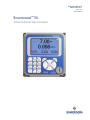
Rosemount
™
56
Advanced Dual-Input Analyzer


Your instrument purchase from Emerson is one of the finest available for your particular application. These instruments
have been designed, and tested to meet many national and international standards. Experience indicates that its perform-
ance is directly related to the quality of the installation and knowledge of the user in operating and maintaining the instru-
m
ent. To ensure their continued operation to the design specifications, personnel should read this manual thoroughly
before proceeding with installation, commissioning, operation, and maintenance of this instrument. If this equipment is
used in a manner not specified by the manufacturer, the protection provided by it against hazards may be impaired.
• Failure to follow the proper instructions may cause any one of the following situations to occur: Loss of life; person-
al injury; property damage; damage to this instrument; and warranty invalidation.
• Ensure that you have received the correct model and options from your purchase order. Verify that this manual
covers your model and options. If not, call 1-800-854-8257 or 949-757-8500 to request correct manual.
• For clarification of instructions, contact your Rosemount representative.
• Follow all warnings, cautions, and instructions marked on and supplied with the product.
• Use only qualified personnel to install, operate, update, program and maintain the product.
• Educate your personnel in the proper installation, operation, and maintenance of the product.
• Install equipment as specified in the Installation section of this manual. Follow appropriate local and national codes.
Only connect the product to electrical sources specified in this manual.
• Use only factory documented components for repair. Tampering or unauthorized substitution of parts and proce-
dures can affect the performance and cause unsafe operation of your process.
• All instrument enclosures must be closed and protective covers must be in place unless qualified personnel are per-
forming maintenance.
WARNING
RIS
K
O
F
E
LECTRI
CA
L S
HO
C
K
Equipment
protec
ted
thr
oughout by
double
ins
ulation.
•
I
ns
tallation and s
ervic
ing
of this
produc
t may
ex
pos
e pers
onnel
to
danger
ous
voltages
.
•
M
ain pow
er w
ired to
s
eparate pow
er
s
our
c
e mus
t
be dis
c
onnec
ted
before s
ervic
ing.
•
Do not operate
or ener
giz
e ins
trument
w
ith
c
as
e
open!
•
Signal
w
ir
ing c
onnec
ted in this
box
mus
t
be rated at
leas
t
240 V
for
Eur
opean
mains
operation.
•
Non-metallic cable strain reliefs do not provide grounding between conduit connections! Use grounding type bush
-
ings an
d jumper
wir
es.
•
Unused cable conduit entrie
s m
ust be
securely sealed by non-flammable closures to provide enclosure integrity in com
-
pliance with
personal saf
e
ty and environmental protection requirements. Unused conduit openings must be sealed with
Type
4X
or IP66 conduit plugs to m
aintain the ingress protection rating (Type 4X)
•
Electrical
installation must
be
in
accordance with the National Electrical Code (ANSI/NFPA-70) and/or any other
applicable
natio
n
al o
r
local
codes.
•O
pe
r
ate
o
n
ly
with
f
r
o
n
t
pan
e
l
f
aste
n
e
d
and in place.
•Safety
and
performa
nc
e require
that
this
instrument be connected and properly grounded through a three-wire power
so
u
r
ce.
•
Pr
o
pe
r
u
se
an
d
co
n
f
igu
ration is the responsibility of the user.
Essential Instructions
Read this page before proceeding

T
his product generates, uses, and can radiate radio frequency energy and thus can cause radio com-
munication interference. Improper installation, or operation, may increase such interference. As tem-
porarily permitted by regulation, this unit has not been tested for compliance within the limits of Class
A computing devices, pursuant to Subpart J of Part 15, of FCC Rules, which are designed to provide
reasonable protection against such interference. Operation of this equipment in a residential area may
cause interference, in which case the user at his own expense, will be required to take whatever meas-
ures may be required to correct the interference.
CAUTION
WARNING
Physical access
Unauthorized personnel may potentially cause significant damage to and/or misconfigura-
tion of end users’ equipment. This could be intentional or unintentional and needs to be pro-
tected against.
Physical security is an important part of any security program and fundamental to protect-
ing your system. Restrict physical access by unauthorized personnel to protect end users’ as-
sets. This is true for all systems used within the facility.

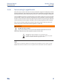
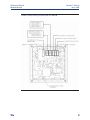
1. Refer to Section 2.0 for mechanical installation instructions.
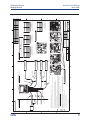
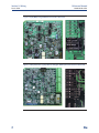
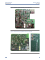
2. Wire sensor(s) to the signal boards. See Section 3.0 for wiring instructions. Refer to the
sensor instruction sheet for additional details. Make current output, alarm relay and
power connections
3. Once connections are secured and verified, apply power to the analyzer.
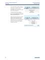
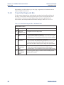
4. When the analyzer is powered up for the first time, Time/Date and Quick Start screens
appear. Quick Start operating tips are as follows:
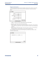
a. Window screens will appear. The field with the focus will appear with dark blue back-
lighting. The field with focus can be edited by press ENTER/MENU.
b. The Time and Date screen to set the real-time clock will appear. Accept the displayed
time by pressing ENTER on Time and date OK or press the down key to Change the
time and date.
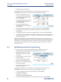
c. The first Quick Start screen appears. Choose the desired language by pressing
ENTER/MENU to edit the active field and scrolling to the language of choice. Press
ENTER/MENU and press the down arrow to highlight NEXT.
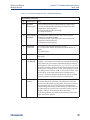
d. The Navigation Rules for operating the keypad will be displayed.
e. Choose the measurement for Sensor 1 (and Sensor 2) and proceed to the remaining
Quick Start steps.
f. Keypad operation guidelines will appear to guide the user how operate the user inter-
face.
g. NOTE: To edit a field with backlit focus, press ENTER/MENU. To scroll up or down, use
the keys to above or below the ENTER key. To move the cursor left or right, use the
keys to the left or right of the ENTER key. To edit a numeric value including decimal
points, use the alphanumeric keypad then press ENTER.
h. NOTE: Press ENTER to store a setting or value. Press EXIT to leave without storing
changes. Pressing EXIT during Quick Start returns the display to the initial start-up
screen (select language). To proceed to the next Quick Start step, use the right key or
the down key to highlight NEXT. Press ENTER.
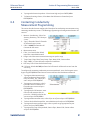
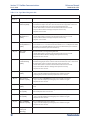
5. After the last step, the main display appears. The current outputs are assigned to default
values before probes are wired to the analyzer. After the last step, the main display ap-
pears. The outputs are assigned to
default values.
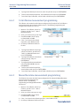
6. To change output, and all settings, press ENTER/MENU from the live screen. Using the
down and right arrow keys, select one of the following menus and navigate the screen of
choice.
7. To return the analyzer to the default settings, choose Reset under the Menu selection
screen.
WARNING
RISK OF ELECTRICAL SHOCK
Electrical installation must be in accordance with the National Electrical Code
(ANSI/NFPA-70) and/or any other applicable national or local codes.
CAUTION: This symbol identifies a risk of electrical shock.
CAUTION: This symbol identifies a potential hazard. When this symbol appears,
consult the manual for appropriate action.
Section i: Quick Start Guide

SAFETY MESSAGES
Procedures and instructions in this section may require special precautions to ensure the
safety of the personnel performing the operations. Information that raises potential safety
issues is indicated by a warning symbol ( ). This symbol identifies a potential hazard.

Contents
Section 1: Description and Specifications
1.1 Features and Applications................................................................................1
1.2 Enhanced Features ..........................................................................................2
1.3 Specifications-General ....................................................................................3
1.4 Contacting Conductivity .................................................................................6
1.5 Toroidal Conductivity ......................................................................................7
1.6 pH/ORP ...........................................................................................................8
1.7 Flow ................................................................................................................9
1.8 4-20 mA Current Input.....................................................................................9
1.9 Chlorine.........................................................................................................10
1.10 Dissolved Oxygen .........................................................................................12
1.11 Dissolved Ozone............................................................................................12
1.12 Turbidity........................................................................................................13
1.13 Ordering Information ....................................................................................14
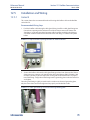
Section 2: Installation
2.1 Unpacking and Inspection .............................................................................15
2.2 Installation ....................................................................................................15
Section: 3 Wiring
3.1 General .........................................................................................................21
3.2 Preparing Conduit Openings .........................................................................22
3.3 Preparing Sensor Cable..................................................................................22
3.4 Power, Output, Alarms and Sensor Connections............................................22
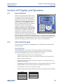
Section 4: Display and Operation
4.1 User Interface ................................................................................................31
4.2 Instrument Keypad........................................................................................31
4.3 Main Display ..................................................................................................31
4.4 Menu System.................................................................................................32
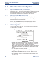
4.5 USB Data Port ................................................................................................33
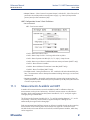
4.6 56 Data Logger and Event Logger Download Procedure ................................33
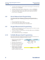
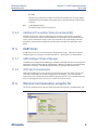
4.7 Software Upgrade .........................................................................................35
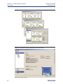
4.8 Configuration Transfer ..................................................................................35
Section 5: Programming the Analyzer - Basics
5.1 General .........................................................................................................37
5.2 Changing the Startup Settings ......................................................................37
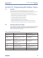
5.3 Programming Temperature .........................................................................38
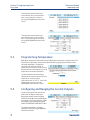
5.4 Configuring and Ranging the Current Outputs ..............................................38
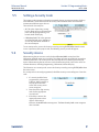
5.5 Setting a Security Code .................................................................................39
5.6 Security Access..............................................................................................39
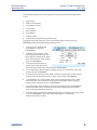
5.7 Using Hold ....................................................................................................40
5.8 Resetting Factory Defaults – Reset Analyzer ..................................................40
5.9 Programming Alarm Relays. ..........................................................................40
Reference Manual Table of Contents
00809-0100-3056 March 2020
Table of Contents i

Section 6: Programming - Measurements
6.1 Programming Measurements – Introduction ................................................43
6
.2 pH .................................................................................................................43
6.3 ORP ..............................................................................................................44
6.4 Contacting Conductivity................................................................................45
6.5 Toroidal Conductivity ....................................................................................46
6.6 Chlorine.........................................................................................................47
6.7 Dissolved Oxygen ..........................................................................................50
6.8 Dissolved Ozone ...........................................................................................51
6.9 Turbidity .......................................................................................................51
6.10 Flow ..............................................................................................................52
6.11 Current Input ................................................................................................52
Section 7: PID Control
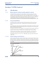
7.1 Introduction .................................................................................................55
7.2 PID Setup.......................................................................................................59
Section 8: Time Proportional Control
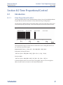
8.1 Introduction .................................................................................................63
8.2 TPC Setup......................................................................................................63
Section 9: Alarm Relay Functions
9.1 General..........................................................................................................67
9.2 High/Low Concentration Alarm .....................................................................67
9.3 Delay Timer: ..................................................................................................68
9.4 Bleed and Feed ..............................................................................................70
9.5 Totalizer Based Relay Activation ....................................................................71
9.6 Interval Timer ................................................................................................72
9.7 Date and Time Activation ..............................................................................74
Section 10: Calibration
10.1 Calibration – Introduction .............................................................................75
10.2 pH Calibration ...............................................................................................75
10.3 ORP Calibration .............................................................................................76
10.4 Contacting Conductivity Calibration .............................................................77
10.5 Toroidal Conductivity Calibration ..................................................................79
10.6 Chlorine Calibration ......................................................................................80
10.7 Oxygen Calibration .......................................................................................82
10.8 Ozone Calibration .........................................................................................84
10.9 Calibrating Temperature ...............................................................................85
10.10 Turbidity .....................................................................................................85
10.11 Pulse Flow ...................................................................................................86
ii Table of Contents
Table of Contents Reference Manual
March 2020 00809-0100-3056

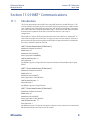
Section 11: HART
®
Communications
11.1 Introduction ..................................................................................................87
11.2 Physical Installation and Configuration ..........................................................88
11.3 Measurements Available via HART.................................................................89
11.4 Diagnostics Available via HART ......................................................................90
11.5 HART Hosts ...................................................................................................91
11.6 Wireless Communication using the 56...........................................................94
11.7 Field Device Specification (FDS).....................................................................94
Section 12: Profibus Communications
12.1 General ..........................................................................................................95
12.2 Profibus Features...........................................................................................95
12.3 Profibus Communications .............................................................................96
12.4 Data Transmission .......................................................................................100
12.5 Installation and Wiring.................................................................................111
Section 13: Maintenance
13.1 Overview .....................................................................................................113
13.2 Analyzer Maintenance .................................................................................113
13.3 USB Port ......................................................................................................113
Section 14: Return of Material
14.1 General........................................................................................................115
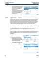
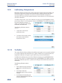
14.2 Warranty Repair ..........................................................................................115
14.3 Non-Warranty Repair ..................................................................................115
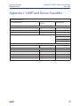
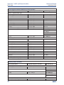
HART Appendix 1 ..................................................................................................117
HART Appendix 2 ..................................................................................................121
Table of Contents iii
Reference Manual Table of Contents
00809-0100-3056 March 2020

iv
Table of Contents Reference Manual
March 2020 00809-0100-3056

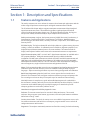
Section 1: Description and Specifications
1.1 Features and Applications
This multi-parameter unit serves industrial, commercial and municipal applications with the
widest range of liquid measurement inputs and digital communications available.
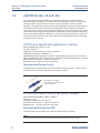
The 56 advanced dual-input analyzer supports continuous measurement of liquid analytical
inputs from one or two sensors. The modular design allows signal input boards to be field
replaced, making configuration changes easy. The high resolution full-color display gives
unsurpassed visibility and functionality for liquid analytical instrumentation.
Dual Input Instrument: single or dual measurement of pH/ORP, Resistivity/ Conductivity, %
Concentration, Total Dissolved Solids, Total Chlorine, Free Chlorine, Monochloramine,
Dissolved Oxygen, Dissolved Ozone, Turbidity, Pulse Flow, Temperature, and 4-20 mA input
from any device.
Full Color Display: The high resolution full-color display allows at-a-glance viewing of process
readings – indoors or outdoors. Six additional process variables or diagnostic parameters are
displayed for quick determination of process or sensor condition. The contrast of back-lit
display can be adjusted and the main screen can be customized to meet user requirements.
Digital Communications: HART
®
version 5 and 7 digital communications are available on the
56. An optional Profibus
®
DP digital communications board is available for Profibus
installations. 56 HART units communicate with the 475 HART hand-held communicator and
HART hosts such as AMS Intelligent Device Manager. 56 Profibus units are fully compatible
with Profibus DP networks and Class 1 or Class 2 masters. HART and Profibus DP configured
units will support any single or dual measurement configurations of the 56.
Menus: Easily-managed window screens for easy navigation to local configuration and routine
calibration. Quick Start and all menu screens are available in multiple locally displayed
languages. Alpha-numeric keypad allows easy entries during configuration and calibration.
Quick Start Programming: Popular Quick Start screens appear the first time the unit is
powered. The instrument auto-recognizes each measurement input type and prompts the
user to configure each sensor loop in a few quick steps for immediate commissioning.
User Help Screens: A complete user guide and troubleshooting manual is embedded in
the instrument’s memory and easily accessed via the INFO key on the local display. Detailed
instructions and troubleshooting tips in multiple languages are intended to provide
adequate guidance to resolve most problems on site.
Hazardous Area Approvals and Safety Approvals: None.
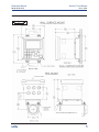
Enclosure: The instrument enclosure fits standard ½ DIN panel cutouts. The versatile
enclosure design supports panel-mount, pipe-mount, and surface/wall-mount installations.
No Enclosure ratings – None.
Security Access Codes: Two levels of security access are available. Program one access code
for routine maintenance and hold of current outputs; program another access code for all
configuration menus and functions.
Diagnostics: The analyzer continuously monitors itself and the sensor(s) for fault and warning
Description and Specifications 1
Reference Manual Section 1: Description and Specifications
00809-0100-3056 March 2020

conditions. A display banner flashes red to indicate a Fault condition and yellow for a
Warning condition to visually alert field personnel. Details and troubleshooting information
for any specific fault or warning can be readily accessed by pressing the INFO key.
Local Languages: Rosemount extends its worldwide reach by offering nine menu languages
– English, French, German, Italian, Spanish, Portuguese, Chinese, Russian and Polish. Every
unit includes user programming menus; calibration routines; faults and warnings; and user
help screens in all nine languages.
Current Outputs: Every unit includes four 4-20 mA or 0-20 mA electrically isolated current
outputs giving the ability to transmit the measurement value and the temperature for both
sensors. Users have wide latitude to assign any measurement value or live diagnostic to any
current output for reporting. Output dampening can be enabled with time constants from 0
to 999 seconds. HART digital communications transmitted via current output 1 is standard
on all units (option code HT).
1.2 Enhanced Features
Process Trending Graphs: High-resolution color graphs of measurement data can be displayed
on-screen to pinpoint process disruptions or measurement problems and to estimate probe
maintenance frequency. The analyzer gives the user the ability to zoom in to a specific
narrow timeframe of process measurements for detailed on-screen evaluation.
Data Logger and Event Logger: Extensive onboard data storage captures measurement data
from both channels every 30 seconds for 30 days for on-screen display or local upload to a
USB 2.0 memory device. 300 significant analyzer events are recorded including start-up
time, calibrations, hold outputs, configurations, alarms, power interruptions, faults, and
more. All process data and events are time/date stamped.
USB 2.0 Data Transfer Port: A USB port is built-in to allow local data transfer of process data
and events using a standard USB memory device. Cleanly formatted EXCEL data is useful for
evaluation of process data on a computer and identification of critical alarm or fault events.
PID Control: Proportional, Integral and Derivative settings allow the analog current outputs
to adjust a control device that has continuous adjustability by acting on process
measurements or temperature. PID is typically used on modulating control devices such as
automated control valves or variable volume pumps. Any current output can be
programmed for PID functions.
Alarm Relay Capabilities: Four Single Pole Double Throw alarm relays are fully assignable
and programmable to trigger alarms upon reaching measurement or diagnostics setpoints
or fault conditions. Further relay settings include TPC, synchronized interval timers and four
specialized timer functions described below. All relays are independently activated. Failsafe
operation and programming of relay default state (normally open or normally closed) is
software selectable.
Timer Functions: Basic TPC (Time Proportional Control) settings are available. Interval
timers set relays by interval time, on-time and recovery time for discrete on/off control
devices based on measurement inputs. In addition, four real-time clock relay functions are
implemented including: bleed and feed, day and time interval timers, delay timer and a flow
totalizer. These advanced timer features support a number of specialized applications that
normally require dedicated timer control devices or DCS programming.
2 Description and Specifications
Section 1: Description and Specifications Reference Manual
March 2020 00809-0100-3056

Wireless Thum Adaptor Compatible: Enable wireless transmissions of process variables and
diagnostics from hard-to-reach locations where it is impractical to run wires for current
o
utputs. When commissioned with the THUM Adaptor, 56 HART
®
u
nits can communicate on
Emerson wireless networks using HART 7 wireless protocol.
Smart-Enabled pH: Rosemount SMART pH capability can eliminate field calibration of pH
probes through automatic upload of calibration data and history – fully calibrating the pH
loop. pH probe changes are literally plug and play using SMART pH sensors with VP cables
connections.
Advanced Functions: Several specialty measurements are supported including: high reference
impedance pH sensors, Ion Selective Electrode measurements, pH loop calibration by
entering pH slope and reference offset, Isopotential point for pH, inferred pH determination
using dual contacting conductivity inputs, differential conductivity, differential flow, totalized
flow, current input from any 4-20 mA source, dual range calibration for chlorine sensors,
programmable polarizing voltage for amperometric oxygen sensors and software selectable
normally open or normally closed alarm relays – to name a few.
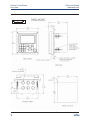
1.3 Specifications - General
Case: Polycarbonate. Type 4X, IP66.
NOTE:
To ensure a water-tight seal, tighten all four front panel screws to 6 in-lbs of torque.
Dimensions: 6.2 x 6.2 x 5.2 in. (157 x 157 x 132 mm)
Conduit openings: Accepts (6) PG13.5 or 1/2 in. conduit fittings
Display: Large 3.75 x 2.2 in. (95.3 x 55.9mm) high resolution color LCD displays large
process variables and user-definable display of diagnostic parameters. Calibration,
programming and information screens display clear, easy-to-read characters. The color
display is back-lit and backlighting intensity is user adjustable. Measurement character
height: (.5") 13mm. Main display can be customized to meet user requirements.
Ambient temperature and humidity: -10 to 60 °C, (14 to 140 °F) RH 5 to 95% (non-
condensing). For Turbidity only: 0 to 55 °C (32 to 131 °F). RH 5 to 95% (non-condensing).
NOTE:
The analyzer is operable from -5 to 55 °C (-23 to 131 °F) with some degradation in display response or
performance. Above 60 °C, the following components will progressively and automatically shut down:
display, USB communications port, current outputs, alarm relays, main circuit board.
Always remove USB memory device at ambient temp above 60 °C. Do not access USB port if
combustible atmosphere is present.
Storage temperature: -20 to 60 °C, (-4 to 140 °F)
Power: Code -02: 20 to 30 VDC. 20 W
Code –03: 85 to 264 VAC, 47.5 to 65.0 Hz, 20 W
Real time clock back-up: 24 hours.
WARNING
Description and Specifications 3
Reference Manual Section 1: Description and Specifications
00809-0100-3056 March 2020

Hazardous Location Approvals:
Options for CSA: 02, 03, 20, 21, 22, 24, 25, 26, 27, 30, 31, 32, 34, 35, 36, 37, 38, HT and DP
C
lass I, Division 2, Groups A, B, C, & D
Class Il, Division 2, Groups E, F, & G
Class Ill
T4 Tamb = 60 °C
Enclosure Type 4X, IP66
See Non-Incendive Field Wiring drawing 1400668. The ‘C’ and ‘US’ indicators adjacent to the CSA
Mark signify that the product has been evaluated to the applicable CSA and ANSI/UL Standards, for
use in Canada and the U.S. respectively. Evaluated to CSA Standards: 22.2 Numbers: 1-10. 0.4-04,
25-1996, 94-M1991, 142-M1987, 213-M1987, 60529:05. ANSI/IEC 60529:04.
ANSI/ISA:12.12.01:2007. UL No. 50:11th Ed. and No. 508:17th Ed.
Note: Single-input Turbidity configurations (models 56-02-27-38 or -HT, 56-03-27-38 or -HT) and dual-
input Turbidity only configurations (56-02-27-37 or -HT, 56-03-27-37 -HT) are CSA approved class I Div.
2 for hazardous area installation.
Options for FM: -02, 03, 20, 21, 22, 23, 24, 25, 26, 27, 30, 31, 32, 33, 34, 35, 36, 37, 38,
HT and DP.
Class I, Division 2, Groups A, B, C, & D
Class Il & lll, Division 2, Groups E, F, & G
T4 -10 °C ≤ Tamb ≤ 60 °C
IP66
S
ee Non-Incendive Field Wiring drawing 1400667.
Evaluated to FM Standards: 3600:2011, 3611:2004, 3810:2005, ANSI/IEC: 60529:2004.
Note: Single-input Turbidity configurations (models 56-02-27-38 or -HT, 56-03-27-38 or -HT) and
dual-input Turbidity only configurations (56-02-27-37 or -HT, 56-03-27-37 or -HT) are FM approved
class I Div. 2 for hazardous area installation.
Ordinary Locations (only with - UL ordering option):
Options for UL: -02, 03, 20, 21, 22, 24, 25, 26, 27, 30, 31, 32, 34, 35, 36, 37, 38,
HT and DP.
Pollution Degree 2: Normally only non-conductive pollution occurs. Occasionally, however, a
temporary conductivity caused by condensation must be expected.
Altitude: for use up to 2000 meter (6562 ft.)
EMI/RFI Effect
Meets all industrial requirements of EN 61326.
HART Analog and Digital Communication
No effect on the values being given if using 4-20 mA analog or HART digital signal with shielded,
twisted pair wiring.
Profibus DP Digital Communication
No effect on the values being given if using Profibus DP digital signal.
Note 1
During EMI disturbance, the maximum sensor deviation is ±0.004 ppm (4 ppb) for options 24, 25, 26,
34, 35, and 36.
LVD: EN-61010-1:2010
4 Description and Specifications
Section 1: Description and Specifications Reference Manual
March 2020 00809-0100-3056
U
L
US
C
LISTED

Reference Manual Section 1: Description and Specifications
00809-0100-3056 March 2020
Description and Specifications 5
Input: One or two isolated sensor inputs. Measurement choices of pH/ORP, resistivity/conductivity/ TDS, %
concentration, ratio conductivity, total and free chlorine, monochloramine, dissolved oxygen,
dissolved ozone, turbidity, pulse flow, temperature and raw 4-20 mA input. For contacting
conductivity measurements, temperature element can be a Pt100 RTD or Pt1000 RTD. For other
measurements (except ORP, flow and turbidity), use either a PT100 RTD, PT1000 RTD, or 22k NTC
(D.O. only).
Outputs: Four 4-20 mA or 0-20 mA isolated current outputs. Fully scalable. Max Load: 550
Ohms. Output 1 superimposes the HART
®
digital signal. Outputs can be programmed for
PID control. Output dampening can be enabled with time constants from 0 to 999 seconds.
HART digital communications transmitted via current output 1 is standard on all units
(option code HT).
Alarms: Four alarm relays for process measurement(s) or temperature. Any relay can be
programmed for any measurement, timer, TPC or fault alarm operation, instead of a process
alarm. When selected, a fault alarm will activate the relay when a sensor or analyzer fault
occurs. Each relay can be configured independently. Alarm logic (high or low activation or
USP*) and deadband are user-programmable.
*USP alarm can be programmed to activate when the conductivity is within a user-selectable percentage of the
limit. conductivity/resistivity measurement only)
Relays: Form C, SPDT, epoxy sealed
Inductive load: 1/8 HP motor (max.), 115/240 VAC
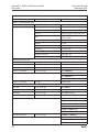
Terminal Connections Rating:
Power connector ( 02 order code, 24 VDC power supply and 03 order code, 85-264 VAC
power supply): 24-12 AWG wire size.
Signal board terminal blocks: 26-16 AWG wire size.
Current output connectors: 26-16 AWG wire size.
Alarm relay terminal blocks: 24-12 AWG wire size.
Weight/Shipping Weight: (rounded up to nearest lb or nearest 0.5 kg): 3 lbs/4 lbs
(1.5 kg/2.0 kg)
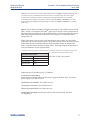
Maximum Relay Current
Power Input Resistive
28 VDC 5.0 A 5.0 A
115 VAC 5.0 A 5.0 A
230 VAC 5.0 A 5.0 A

±0.6% of reading in recommended range
+2 to -10% of reading outside high recommended range
±5% of reading outside low recommended range
±4% of reading in recommended range
1.4 Contacting Conductivity (Codes -20 and -30)
Measures conductivity in the range 0 to 600,000 µS/cm (600 mS/cm). Measurement choices
a
re conductivity, resistivity, total dissolved solids, salinity, and % concentration. Temperature
compensation can be disabled, allowing the analyzer to display raw conductivity.
NOTE:
When two contacting conductivity sensors are used, The 56 can derive an inferred pH value. Inferred
pH is calculated pH, not directly measured pH. Inferred pH is calculated from straight and cation con-
ductivity. It is applicable only if the alkalizing agent is NaOH or NH
3
and the major contaminant is
NaCl. It is strictly an application for power plants.
Performance Specifications - Analyzer
Measurement Range: see table below
Solution temperature compensation: manual slope (X% / °C), high purity water (dilute
sodium chloride), and cation conductivity (dilute hydrochloric acid).
Salinity: uses Practical Salinity Scale
Total Dissolved Solids: Calculated by multiplying conductivity at 25 °C by 0.65
Five percent concentration curves: 0-12% NaOH, 0-15% HCl, 0-20% NaCl, 0-25% or 96-99.7%
H
2
SO
4
. The conductivity concentration algorithms for these solutions are fully temperature
compensated.
Four temperature compensation options: manual slope (X% / °C), high purity water (neutral
salt), cation conductivity (dilute hydrochloric acid) and raw.
Input filter: time constant 1 - 999 sec, default 2 sec.
Response time: 3 seconds to 95% of final reading
Recommended Sensors for Contacting Conductivity:
All Rosemount ENDURANCE 400 series conductivity sensors (Pt 1000 RTD) and 410VP 4-
electrode high-range conductivity sensor.
Temperature range 0-200 °C
Temperature Accuracy,
Pt-1000, 0-50 °C
± 0.1 °C
Temperature Accuracy,
Pt-1000, Temp. > 50 °C
± 0.5 °C
Temperature Specifications:
Cell Constant Linearity
6 Description and Specifications
Section 1: Description and Specifications Reference Manual
March 2020 00809-0100-3056
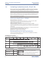
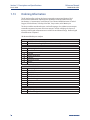
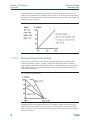
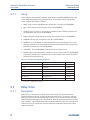
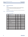
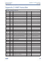
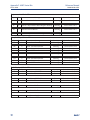
Cell 0.01 S/cm 0.1 µS/cm 1.0 µS/cm 10 µS/cm 100 µS/cm 1000 µS/cm 10mS/cm 100mS/cm 1000mS/cm
Constant
0.01
0.1
1.0
4-electrode
0.01 µS/cm to 200 µS/cm
0.1 µS/cm to 2000 µS/cm
1 µS/cm to 20mS/cm
2 µS/cm to 1400 mS/cm
200 µS/cm to 6000 µS/cm
2000 µS/cm to 60 mS/cm
20 mS/cm to 600 mS/cm
PERFORMANCE SPECIFICATIONS
Recommended Range – Contacting Conductivity

Description and Specifications 7
Reference Manual Section 1: Description and Specifications
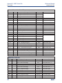
00809-0100-3056 March 2020
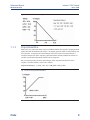
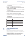
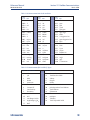
Model 1 µS/cm 10 µS/cm 100 µS/cm 1000 µS/cm 10 mS/cm 100 mS/cm 1000 mS/cm 2000 mS/cm
5 µS/cm to 500 mS/cm
15 µS/cm to 1500 mS/cm
500 mS/cm to 2000
500 µS/cm to 2000 mS/cm
100 µS/cm to 2000 mS/cm
1500 mS/cm to 2000 mS/cm
226
242
222
(1in & 2in)
225 & 228
1.5 Toroidal Conductivity (Codes -21 and -31)
Measures conductivity in the range of 1 (one) µS/cm to 2,000,000 µS/cm (2 S/cm). Measurement
c
hoices are conductivity, resistivity, total dissolved solids, salinity, and % concentration.
Temperature compensation can be disabled, allowing the analyzer to display raw conductivity.
For more information concerning the use and operation of the toroidal conductivity sensors,
refer to the product data sheets.
Performance Specifications- Analyzer
Measurement Range: see table below
Repeatability: ±0.25% ±5 µS/cm after zero cal
Salinity: uses Practical Salinity Scale
Total Dissolved Solids: Calculated by multiplying conductivity at 25 °C by 0.65
Five percent concentration curves: 0-12% NaOH, 0-15% HCl, 0-20% NaCl, 0-25% or 96-99.7%
H2SO4. The conductivity concentration algorithms for these solutions are fully temperature
compensated. For other solutions, the analyzer accepts as many as five data points and fits
either a linear (two points) or a quadratic function (three or more points) to the data.
Reference temperature and linear temperature slope may also be adjusted for optimum
results.
Three temperature compensation options: manual slope (X% / °C), neutral salt (dilute
sodium chloride) and raw.
Input filter: time constant 1 - 999 sec, default 2 sec.
Response time: 3 seconds to 95% of final reading
Recommended Sensors:
All Rosemount submersion/immersion and flow-through toroidal sensors.
Temperature range
-25 to 210 °C
(-13 to 410 °F)
Temperature Accuracy,
Pt-100, -25 to 50 °C
± 0.5 °C
Temperature Accuracy,
Pt-100,. 50 to 210 °C
± 1°C
PERFORMANCE SPECIFICATIONS Recommended Range - Toroidal Conductivity
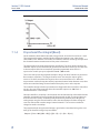
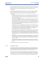
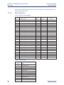
226: ±1% of reading ±5 µS/cm in recommended range
225 & 228: ±1% of reading ±10 µS/cm in
recommended range
222, 242: ±4% of reading in recommended range
225, 226 & 228: ±5% of reading outside high
recommended range
226: ±5 µS/cm outside low recommended range
225 & 228: ±15 µS/cm outside low recommended
range
Loop Performance (Following Calibration)

8 Description and Specifications
Section 1: Description and Specifications Reference Manual
March 2020 00809-0100-3056
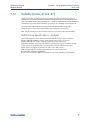
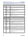
1.6 pH/ORP (Codes -22 and -32)
For use with any standard pH or ORP sensors. Measurement choices are pH, ORP, Redox,
A
mmonia, Fluoride or custom ISE. The automatic buffer recognition feature uses stored buffer
pH values and their temperature curves for the most common buffer standards available
worldwide. The analyzer will recognize the pH value of the buffer being measured and perform a
self stabilization check on the sensor before completing the calibration. Manual or automatic
temperature compensation is menu selectable. Change in process pH due to temperature can be
compensated using a programmable temperature coefficient. For more information concerning
the use and operation of the pH or ORP sensors, refer to sensor product data sheets. The 56 can
also derive an inferred pH value. Inferred pH can be derived and displayed when two contacting
conductivity sensors are used.
Performance Specifications (pH input) - Analyzer
Measurement Range [pH]: 0 to 14 pH
Accuracy: ±0.01 pH
Diagnostics: glass impedance, reference impedance
Temperature coefficient: ±0.002pH / °C
Solution temperature correction: pure water, high pH (dilute base), Ammonia and custom
Buffer recognition: NIST (including non-NIST pH 7.01 buffer), DIN 19267, Ingold, Merck, and Fisher
Input filter: Time constant 1 - 999 sec, default 4 sec.
Response time: 5 seconds to 95% of final reading
Recommended Sensors for pH:
Compatible with standard pH sensors with and without integral preamps. Supports Smart
pH sensors from Rosemount (includes Smart integral preamps).
Performance Specifications (ORP input) - Analyzer
Measurement Range [ORP]: -1500 to +1500 mV
Accuracy: ± 1 mV
Temperature coefficient: ±0.12mV / °C
Input filter: Time constant 1 - 999 sec, default 4 sec.
Response time: : 5 seconds to 95% of final reading
Recommended Sensors for ORP:
Compatible with standard ORP sensors with and without integral preamps.
NOTE:
Some older sensor preamps may not be compatible with the 56 (contact the factory for details).
General purpose and high
performance pH 396PVP, 3900VP
and 3300HT sensors

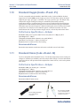
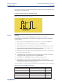
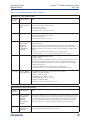
1.7 Flow (Code -23 and -33)
For use with most pulse signal flow sensors, the 56 user-selectable units of measurement
i
nclude flow rates in GPM (gallons per minute), GPH (gallons per hour), cu ft/min (cubic feet
per min), cu ft/hour (cubic feet per hour), LPM (liters per minute), LPH (liters per hour), or
m3/hr (cubic meters per hour), and velocity in ft/sec or m/sec. When configured to measure
flow, the unit also acts as a totalizer in the chosen unit (gallons, liters, or cubic meters). Dual
flow instruments can be configured as a % recovery, flow difference, flow ratio, or total
(combined) flow.
Performance Specifications - Analyzer
Frequency Range: 3 to 1000 Hz
Flow Rate: 0 - 99,999 GPM, LPM, m3/hr, GPH, LPH, cu ft/min, cu ft/hr.
Totalized Flow: 0 – 9,999,999,999,999 Gallons or m3, 0 – 999, 999,999,999 cu ft.
Accuracy: 0.5%
Input filter: Time constant 0-999 sec., default 5 sec.
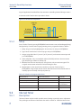
1.8 4-20 mA Current Input (Codes -23 and -33)
For use with any transmitter or external device that transmits 4-20 mA or 0-20 mA current
outputs. Typical uses are for temperature compensation of live measurements (except ORP,
turbidity and flow) and for continuous pressure input for continuous measurement of % oxygen
gas. External input of atmospheric pressure for oxygen measurement allows continuous
partial pressure compensation while the 56 enclosure is completely sealed.
Externally sourced current input is also useful for calibration of new or existing sensors that
require temperature measurement or atmospheric pressure inputs. In addition to live
continuous compensation of live measurements, the current input board can also be used
simply to display and trend the measured temperature or the calculated partial pressure from
the external device. This feature leverages the large display variables on the 56 as a convenience
for technicians. Temperature can be displayed in °C or °F. Partial pressure can be displayed in
inches Hg, mm Hg, atm (atmospheres), kPa (kiloPascals), bar or mbar. The current input
board serves as a power supply for loop-powered devices that do not actively power their 4-
20 mA output signals.
Performance Specifications
Measurement Range *[mA]: 0-20 or 4-20
Accuracy: ±0.03 mA
Input filter: Time constant 0-999 sec., default 5 sec.
*Current input not to exceed 22 mA
Description and Specifications 9
Reference Manual Section 1: Description and Specifications
00809-0100-3056 March 2020

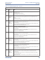
1.9 Chlorine (Code -24 and -34)
Free and Total Chlorine
T
he 56 is compatible with the 499ACL-01 free chlorine sensor and the 499ACL-02 total
chlorine sensor. The 499ACL-02 sensor must be used with the TCL total chlorine sample
conditioning system. The 56 fully compensates free and total chlorine readings for changes
in membrane permeability caused by temperature changes.
For free chlorine measurements, both automatic and manual pH corrections are available.
For automatic pH correction, select code P and an appropriate pH sensor. For more
information concerning the use and operation of the amperometric chlorine sensors and the TCL
measurement system, refer to the product data sheets.
Performance Specifications - Analyzer
Resolution: 0.001 ppm or 0.01 ppm – selectable
Input Range: 0nA – 100 µA
Automatic pH correction (requires Code P): 6.0 to 10.0 pH
Temperature compensation: Automatic or manual (0-50 °C).
Input filter: Time constant 1 - 999 sec, default 5 sec.
Response time: 6 seconds to 95% of final reading
Recommended Sensors
Chlorine: 499ACL-01 Free Chlorine or 499ACL-02 Total Chlorine
pH: The following pH sensor is recommended for automatic pH correction of free chlorine
readings: 3900
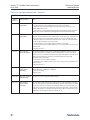
Monochloramine
The 56 is compatible with the 499A CL-03 Monochloramine sensor. The 56 fully
compensates readings for changes in membrane permeability caused by temperature
changes. Because monochloramine measurement is not affected by pH of the process, no
pH sensor or correction is required. For more information concerning the use and operation
of the amperometric chlorine sensors, refer to the product data sheets.
Performance Specifications - Analyzer
Resolution: 0.001 ppm or 0.01 ppm – selectable
Input Range: 0 nA – 100 µA
Temperature compensation: Automatic or manual (0-50 °C).
Input filter: Time constant 1 - 999 sec, default 5 sec.
Response time: 6 seconds to 95% of final reading
Recommended Sensors
Rosemount 499ACL-03 Monochloramine sensor
10 Description and Specifications
Section 1: Description and Specifications Reference Manual
March 2020 00809-0100-3056
Page is loading ...
Page is loading ...
Page is loading ...
Page is loading ...
Page is loading ...
Page is loading ...
Page is loading ...
Page is loading ...
Page is loading ...
Page is loading ...
Page is loading ...
Page is loading ...
Page is loading ...
Page is loading ...
Page is loading ...
Page is loading ...
Page is loading ...
Page is loading ...
Page is loading ...
Page is loading ...
Page is loading ...
Page is loading ...
Page is loading ...
Page is loading ...
Page is loading ...
Page is loading ...
Page is loading ...
Page is loading ...
Page is loading ...
Page is loading ...
Page is loading ...
Page is loading ...
Page is loading ...
Page is loading ...
Page is loading ...
Page is loading ...
Page is loading ...
Page is loading ...
Page is loading ...
Page is loading ...
Page is loading ...
Page is loading ...
Page is loading ...
Page is loading ...
Page is loading ...
Page is loading ...
Page is loading ...
Page is loading ...
Page is loading ...
Page is loading ...
Page is loading ...
Page is loading ...
Page is loading ...
Page is loading ...
Page is loading ...
Page is loading ...
Page is loading ...
Page is loading ...
Page is loading ...
Page is loading ...
Page is loading ...
Page is loading ...
Page is loading ...
Page is loading ...
Page is loading ...
Page is loading ...
Page is loading ...
Page is loading ...
Page is loading ...
Page is loading ...
Page is loading ...
Page is loading ...
Page is loading ...
Page is loading ...
Page is loading ...
Page is loading ...
Page is loading ...
Page is loading ...
Page is loading ...
Page is loading ...
Page is loading ...
Page is loading ...
Page is loading ...
Page is loading ...
Page is loading ...
Page is loading ...
Page is loading ...
Page is loading ...
Page is loading ...
Page is loading ...
Page is loading ...
Page is loading ...
Page is loading ...
Page is loading ...
Page is loading ...
Page is loading ...
Page is loading ...
Page is loading ...
Page is loading ...
Page is loading ...
Page is loading ...
Page is loading ...
Page is loading ...
Page is loading ...
Page is loading ...
Page is loading ...
Page is loading ...
Page is loading ...
Page is loading ...
Page is loading ...
Page is loading ...
Page is loading ...
Page is loading ...
Page is loading ...
-
 1
1
-
 2
2
-
 3
3
-
 4
4
-
 5
5
-
 6
6
-
 7
7
-
 8
8
-
 9
9
-
 10
10
-
 11
11
-
 12
12
-
 13
13
-
 14
14
-
 15
15
-
 16
16
-
 17
17
-
 18
18
-
 19
19
-
 20
20
-
 21
21
-
 22
22
-
 23
23
-
 24
24
-
 25
25
-
 26
26
-
 27
27
-
 28
28
-
 29
29
-
 30
30
-
 31
31
-
 32
32
-
 33
33
-
 34
34
-
 35
35
-
 36
36
-
 37
37
-
 38
38
-
 39
39
-
 40
40
-
 41
41
-
 42
42
-
 43
43
-
 44
44
-
 45
45
-
 46
46
-
 47
47
-
 48
48
-
 49
49
-
 50
50
-
 51
51
-
 52
52
-
 53
53
-
 54
54
-
 55
55
-
 56
56
-
 57
57
-
 58
58
-
 59
59
-
 60
60
-
 61
61
-
 62
62
-
 63
63
-
 64
64
-
 65
65
-
 66
66
-
 67
67
-
 68
68
-
 69
69
-
 70
70
-
 71
71
-
 72
72
-
 73
73
-
 74
74
-
 75
75
-
 76
76
-
 77
77
-
 78
78
-
 79
79
-
 80
80
-
 81
81
-
 82
82
-
 83
83
-
 84
84
-
 85
85
-
 86
86
-
 87
87
-
 88
88
-
 89
89
-
 90
90
-
 91
91
-
 92
92
-
 93
93
-
 94
94
-
 95
95
-
 96
96
-
 97
97
-
 98
98
-
 99
99
-
 100
100
-
 101
101
-
 102
102
-
 103
103
-
 104
104
-
 105
105
-
 106
106
-
 107
107
-
 108
108
-
 109
109
-
 110
110
-
 111
111
-
 112
112
-
 113
113
-
 114
114
-
 115
115
-
 116
116
-
 117
117
-
 118
118
-
 119
119
-
 120
120
-
 121
121
-
 122
122
-
 123
123
-
 124
124
-
 125
125
-
 126
126
-
 127
127
-
 128
128
-
 129
129
-
 130
130
-
 131
131
-
 132
132
-
 133
133
-
 134
134


Rosemount 56 Advanced Dual-Input Analyzer Owner's manual
- Category
- Measuring, testing & control
- Type
- Owner's manual
Ask a question and I''ll find the answer in the document
Finding information in a document is now easier with AI
Related papers
-
Rosemount 1066 Smart-Enabled, 2-WireTransmitter Owner's manual
-
-
-
-
-
-
-
-
-
Other documents
-
Lovibond Single Method SD 70 - Conductivity User manual
-
 Hach ORBISPHERE K1200 Basic User Manual
-
 Hach ORBISPHERE 410 Basic User Manual
-
 Hach Polymentron 9500 Basic User Manual
-
 Hach ORBISPHERE K-M1100 Basic User Manual
-
-
Hach SC200 Basic User Manual
-
 Hach Polymetron 9523sc pH Basic User Manual
-
 Hach 9586sc Basic User Manual
-
Mettler Toledo 2000 Two-Channel Instrument for pH, ORP, Conductivity, Resistivity, Dissolved Oxygen, Dissolved OzoneThornton Instruments User manual


