Page is loading ...

AW05
Control
Operating instructions
\\MAINMENU\STATUS
Circuit B Total Capacity
CAPB_T 0 %
DEM_LIM 100 %
SP 4.2 °C
CTRL_PNT -28.9 °C
EMSTOP dsable
ENTE R
STAR T/ ST OP

2
Operating instructions - VMGFH102
The cover graphics are solely for illustration and forms no part of any offer for sale or any sale contract. The
manufacturer reserves the right to change the design at any time without notice.
Contents
1 SAFETY CONSIDERATIONS ................................................................................................................................................. 3
1.1 - General ..............................................................................................................................................................................................................................3
1.2 - Avoid electrocution.......................................................................................................................................................................................................3
2 GENERAL DESCRIPTION ......................................................................................................................................................3
2.1 - General ..............................................................................................................................................................................................................................3
2.2 - Abbreviations used .......................................................................................................................................................................................................3
3 HARDWARE DESCRIPTION ..................................................................................................................................................3
3.1 - General ..............................................................................................................................................................................................................................3
3.2 - Electrical supply to boards .........................................................................................................................................................................................4
3.3 - Light emitting diodes on boards..............................................................................................................................................................................4
3.4 - The sensors .......................................................................................................................................................................................................................4
3.5 - The controls .....................................................................................................................................................................................................................4
3.6 - Connections at the user terminal block ................................................................................................................................................................4
4. SETTING UP CONTROL SYSTEM ..........................................................................................................................................6
4.1 - General features .............................................................................................................................................................................................................6
4.2 - Default screen characteristics ...................................................................................................................................................................................6
4.3 - Password screens ...........................................................................................................................................................................................................6
4.4 - Menu screen characteristics ......................................................................................................................................................................................6
4.5 - Data screen or configurable parameter characteristics ...................................................................................................................................6
4.6 - Parameter modification ...............................................................................................................................................................................................7
4.7 - Operating mode screen ...............................................................................................................................................................................................7
4.8 - Menu tree structure ......................................................................................................................................................................................................8
4.9 - Detailed menu description ........................................................................................................................................................................................9
5 CONTROL OPERATION .......................................................................................................................................................15
5.1 - Start/stop control....................................................................................................................................................................................................... .15
5.2 - Heat exchanger water pump control ................................................................................................................................................................. .15
5.3 - Control interlock contact ........................................................................................................................................................................................ .15
5.4 - Heat exchanger frost protection .......................................................................................................................................................................... .15
5.5 - Control point ............................................................................................................................................................................................................... .15
5.6 - Capacity limitation .................................................................................................................................................................................................... .16
5.7 - Capacity control ......................................................................................................................................................................................................... .16
5.8 - Defrost function ......................................................................................................................................................................................................... .16
5.9 - Additional electric heater stage control ............................................................................................................................................................ .17
5.10 - Control of a boiler ....................................................................................................................................................................................................17
5.11 - Eco function .............................................................................................................................................................................................................. .17
5.12 - Master/slave assembly .......................................................................................................................................................................................... .17
6 DIAGNOSTICS TROUBLESHOOTING ..............................................................................................................................18
6.1 - General .......................................................................................................................................................................................................................... .18
6.2 - Displaying alarms ...................................................................................................................................................................................................... .18
6.3 - Resetting alarms ......................................................................................................................................................................................................... .18
6.4 - Alarm codes ................................................................................................................................................................................................................. .19

3
Operating instructions - VMGFH102
1 SAFETY CONSIDERATIONS
1.1 - General
Installation, start-up and servicing of equipment can be
hazardous if certain factors particular to the installation are not
considered: operating pressures, presence of electrical
components and voltages and the installation site (elevated
plinths and built-up up structures). Only properly qualified
installation engineers and highly qualified installers and
technicians, fully trained for the product, are authorised to
install and start-up the equipment safely. During all servic-
ing operations all instructions and recommendations which
appear in the installation and service instructions for the
product, as well as on tags and labels fixed to the equipment
and components and accompanying parts supplied sepa-
rately, must be read, understood and followed.
• Apply all standard safety codes and practices.
• Wear safety glasses and gloves.
• Use the proper tools to move heavy objects. Move units
carefully and set them down gently.
1.2 - Avoid electrocution
Only personnel qualified in accordance with IEC (Inter-
national Electrotechnical Commission) recommendations
may be permitted access to electrical components. It is
particularly recommended that all sources of electricity to
the unit be shut off before any work is begun. Shut off the
main power supply at the main circuit breaker or isolator.
IMPORTANT: This equipment conforms to all applicable
codes regarding electromagnetic compatibility.
2 GENERAL DESCRIPTION
2.1 - General
An electronic control system is used to regulate the AW05
units.
These units have only one refrigerant circuit.
The control system regulates the following:
• compressor start-up to control the water loop
• the fans to optimise operation of each refrigerant circuit
• the defrost cycles to ensure the operation of the
refrigerant circuit.
As standard the control system offers three on/off
commands:
• Local - on/o command using the keyboard
• Remote - wired on/o command using volt-free
contacts
• Network - Comfort Network (CCN) on/o command.
The command type is selected in advance by keyboard.
2.2 - Abbreviations used
In this manual, the compressors are labelled A1 and A2.
The following abbreviations are used frequently:
CCN Comfort Network
LED Light Emitting Diode
LEN Internal communication bus linking the main
board to the slave boards
SCT Saturated condensing temperature
SST Saturated suction temperature
EXV Electronic expansion valve
PD-AUX Auxiliary input/output board
3 HARDWARE DESCRIPTION
3.1 - General
The control system consists of an NRCP2-BASE board (that
can control up to two compressors), a PD-AUX board (that
allows control of the different electric heater stages), an EXV
board (that ensures the control of the EXV function) and a
user interface. Certain options may require a number of
additional PD-AUX boards.
All boards communicate via an internal LEN bus. The NRCP2-
BASE board contains the complete control program for the
machine, and continuously manages the recovery of the
values of the various temperature and pressure sensors.
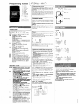
The user interface includes an alphanumeric eight-line
display, two LEDs with five navigation keys as well as a
contrast control wheel.

4
Operating instructions - VMGFH102
Figure 1 - Control board
3.2 - Electrical supply to boards
All boards are supplied from a common 24 V a.c. supply
referred to earth.
In the event of a power supply interrupt, the unit restarts
automatically without the need for an external command.
However, any faults active when the supply is interrupted are
saved and may in certain cases prevent a circuit or unit from
restarting.
CAUTION: Maintain the correct polarity of the power supply
connection of the boards, to ensure that they are not
damaged.
3.3 - Light emitting diodes on boards
All boards continuously check and indicate the proper
operation of their electronic circuits. A light emitting diode
(LED) lights on each board when it is operating properly.
• The red LED that ashes for a two-second period - one
second on, one second off - indicates correct operation. A
different rate indicates a board or a software failure.
• The green LED ashes continuously on all boards to
show that the board is communicating correctly over its
internal bus. If the LED is not ashing, this indicates a
LEN bus wiring problem.
• The orange LED of the master board ashes during any
communication via the CCN bus.
3.4 - The sensors
Pressure sensors
Two types of electronic sensors are used:
• low pressure: suction pressure and pump entering
pressure (optional),
• high pressure: discharge pressure and economiser
pressure.
Thermistors
The heat exchanger water sensors are installed in the entering
and leaving side. The outdoor temperature sensor is
mounted under a metal plate. An additional sensor placed on
an air heat exchanger pipe ensures defrost operation.
3.5 - The controls
Water circulation pump
The controller regulates the heat exchanger water pumps.
Heaters
They protect the heat exchanger (and the piping for units
without pump) against frost, if the unit has stopped and is
energised.
Boiler
This output authorises start/stop of a boiler.
3.6 - Connections at the user terminal block
3.6.1 - General description
The contacts below are available at the user terminal block
on the NRCP2-BASE boards. Some contacts can only be used
if the unit operates in remote operating type (Remote).
\\MAINMENU\STATUS
Circuit B Total Capacity
CAPB_T 0 %
DEM_LIM 100 %
SP 4.2 °C
CTRL_PNT -28.9 °C
EMSTOP dsable
ENTER
START/ S TOP
Contrast control
wheel
Back to the previous
screen
On/off key
- Unit stopped
- List of available operating
modes (only in local mode)
Green LED
Unit has stopped
Unit starts up
Unit in operation
Red LED
No alarm
Warning
Circuit or complete unit error
Up/Down key
- Navigation
- Modification
Enter key
- Validation
- Selection access

5
Operating instructions - VMGFH102
NRCP2-BASE control board Optional PD-AUX board
NRCP2-BASE board connections
Connector/channel Type Terminal Description
CH 08/J4 DI 32-33 Remote on/off switch
CH 09/J4 DI Customer safety loop input (0 = fault, 1 = OK)
CH 10/J4 DI 73-74 Capacity limitation selection
CH 12/J5 DI Setpoint selection
CH 13/J5 DI Power detection input (micro-cut protection)
CH 20/J2B DO Reversible four-way valves
CH 21/J2B DO Water heater command
XXXX/J12 Series RJ-45 series connection
- Pin 1: signal +
- Pin 2: ground
- Pin 3: signal -
J2A
J2B
J3
J4
J12
J3
J11
J10
J9B
J9A
J5
J6
J7A J7B J8
J1
J2
J6
J5
J4
J9
J8
J7
3.6.2 - Volt-free on/off contact
If the unit works in the remote operating mode (Remote) the
operation of the on/off contact is as follows:
Without multiplexing
Off On heating
On/off contact Open Closed
With multiplexing
Off On heating On auto
On/off contact Open Closed Open
3.6.3 - Volt-free setpoint selection contact
Heating
hsp 1 hsp 2
Set point selection contact Open Closed
3.6.4 - Volt-free capacity limitation selection contact
100% Limit
Capacity limitation Open Closed

6
Operating instructions - VMGFH102
4. SETTING UP CONTROL SYTEM
4.1 - General features
The interface includes different screens that are listed below:
• Default screens with direct display of the main
parameters,
• Menu screens for navigation,
• Data/conguration screens listing the parameters by
type,
• Operating mode selection screen,
• Password entry screen,
• Parameter modication screen.
NOTE: If the interface is not used for a long period, it will go
black. The control is always active, the operating mode
remains unchanged. The interface screen is re-animated,
when the user presses a key. Pressing the key once illumi-
nates the screen, pressing the key a second time leads to a
screen that is related to the context and the key symbol.
4.2 - Default screen characteristics
There are four default screens. Each screen shows:
• The unit status, its screen number,
• Three displayed parameters.
LOCAL OFF 1 On the left the unit status, on the right
the screen number
Entering water temp Description of the first parameter
EWT 40°C Abbreviation and value with unit of
measurement of the first parameter
Leaving water temp Description of the second parameter
LWT 46°C Abbreviation and value with unit of
measurement of the second parameter
Outside air temperature Description of the third parameter
OAT 4°C Abbreviation and value with unit of
measurement of the third parameter
Pressing the Up or Down key changes one default screen to
another default screen. The screen number is updated.
4.3 - Password screens
Enter password Description of the password entry
screen
0_** Password value
(0 = basic access) Description
The password is entered digit by digit. The cursor is shown at
the current digit that ashes. The arrow keys modify the digit
value. The digit modification is validated with the Enter key
and the cursor is moved to the next digit.
Enter password
1_** The first digit is 1, the cursor is
positioned on the second digit
(0 = basic access)
Enter password
11_**
(0 = basic access)
Pressing the Enter key at a digit without value validates the
overall selection of the password. The screen is refreshed by
the menu list, and the items displayed depend on the level of
the activated password.
The entry of an incorrect password keeps the password entry
screen.
Password selection 0 (zero) can simply be made by pressing
the Enter key twice in succession.
4.4 - Menu screen characteristics
\\MAINMENU Current path in the menu structure
GENUNIT HYDROKIT Selection cursor to the left of the first
column
TEMP RUNTIME
PRESSURE MODES Menu list
SETPOINT LOGOUT
INPUTS
OUTPUTS
General Parameters Menu Description of the menu framed by the
selection cursor
Each menu item defines the access to categorised data. The
Up and Down arrows position the cursor at the current item. The
Enter key activates the display of the selected sub-menu.
The item LOGOUT permits exiting from the menu screen and
protects access by a user password. The “Previous” key
permits exiting from the current screen without deactivating
the password-protected access.
4.5 - Data screen or configurable parameter
characteristics
The data screens display information parameters such as
temperatures or pressures. The configuration screens display
unit control parameters such as the water temperature
setpoints.

7
Operating instructions - VMGFH102
\\MAINMENU\TEMP Current path in the menu structure
EWT 40°C List of items
LWT 46°C Cursor position
OAT 4°C
CHWSTEMP 46°C
SCT_A 49°C
Leaving Water Temperature Description of the item framed by the
selection cursor
The Up and Down arrow keys position the cursor on the
current menu item. The Enter key activates the parameter
modification (if possible). Any non-pertinent modification
attempt is blocked by a refusal screen.
4.6 - Parameter modification
A configuration parameter can be modified by positioning
the cursor and then pressing the Enter key.
\\MAINMENU\SETPOINT Current path in the menu structure
hps1 45°C List of items
hps2 45°C Cursor position
hramp_sp 0.6°C
lim_sp1 100%
hramp_sp 27.4°C
Heating Setpoint 2 Description of the item framed by the
selection cursor
The following screen allows modification of a parameter.
Modify value Screen description
hsp 1
45 °C Current value
_ °C Cursor position
Heating Setpoint 2 Item description
The Up and Down arrow keys permit the selection of the rst
digit. Pressing the Up key successively scrolls up to the
following symbols:
0, 1, 2, 3, 4, 5, 6, 7, 8, 9, ., -.
The Down key follows the reverse order of the Up key in
scrolling down the digit list above. Each digit is validated
with the Enter key.
The - sign is only accessible for the first selected character.
Modify value Description of the screen
hsp 2
45 °C Current value
46 °C New value before validation
Heating Setpoint 2 Item description
The value is validated with the Enter key. At any time the
return key cancels the current modification.
ATTENTION: If the user exits from the current data screen, the
value is saved. A saving confirmation is displayed. The
Enter key validates the parameter modification(s). The
Return to the Previous Screen key cancels the current
modification(s).
\\MAINMENUSETPOINT Current path in the menu structure
Save changes? Confirmation that the modification is
saved
4.7 - Operating mode screen
The unit is in Local Off mode, pressing the on/off (0/1) key
once activates the display of the operating mode screen.
Select Machine Mode Description of the screen
Local On List of the machine operating modes
Local Schedule Cursor
CCN
Remote
The Up and Down keys position the cursor on the selected
operating mode. Four modes are immediately displayed on
the screen. To access operating modes that are not visible,
please use the Up and Down keys.
When the operating mode has been selected, the new
operating mode can be validated with the Enter key.
Command accepted Operating mode validation screen
When the unit is in an operating mode and the On/o key is
pressed, the unit will stop. A confirmation screen protects the
unit against inadvertent shutdowns.
PRESS ENTER Machine shutdown confirmation
screen
TO CONFIRM STOP

8
Operating instructions - VMGFH102
4.8 - Menu tree structure
HOLIDAY
Jours féri és
BRODCAST
.
GENUNIT
TEMP
PRESSURE
SETPOINT
INPUTS
OUTPUTS
RUNTIME
MODES
ALARMS
CONFIG
LOGOUT
LANGUAGES
QCK_TEST
MAINTAIN
ALARMRST
CUR_ALRM
ALMHIST1
GENCONF
PUMPCONF
HCCONFIG
RESETCFG
USERCONF
SCHEDULE
HOLIDAY
BRODCAST
DATETIME
CTRL_ID
DISPLAY
FACTORY
SERVICE
MST_SLV
CP_UNABL
HOLIDY01S
HOLIDY16S
HOLIDY02S
…
OCC1P01S
OCC1P02S
LOADFACT
M_MSTSLV
DEFROSTM
LAST_POR
PR_LIMIT
SERMAINT
OCCDEFCM
NAVIGATION
Password = "0"
ACCESS
ALL
USER
General parameters
Temperatures
Pressures
Setpoint
Inputs
Outputs
Unit status
Operating time
Language selection
Alarm menu
Configuration menu
Disconnection
Reset of the alarms
Current alarms
Alarm history
Time schedule
Holidays
General configuration
Pump configuration
Heating mode configuration
Setpoint reset
User conguration
Interface configuration
Date and time
Identification control
SHUTDOWN
CONFIRMATION
SCREEN
LIST OF OPERATING
MODES
(only in local)
Schedule 1
Schedule 2
Holidays 1
Holidays 2
Holidays16
SERVICE
FACTORY
DEFAULT
SCREENS
PASSWORD
Already connected
Quick test
Maintenance menu
Factory configuration
Service configuration
Master/slave configuration
Compressors out of service

9
Operating instructions - VMGFH102
4.9 - Detailed menu description
ATTENTION: Depending on the unit characteristics, certain menu items are not used.
4.9.1 - GENUNIT menu
NAME FORMAT UNIT NOTE DESCRIPTION
CTRL_TYP 0/1/2 - 1 Control mode type
STATUS 0-9 - 2 Operating status
min_left 0-15 min Start-up delay
LSP_SEL 0/1/2 - 11 Setpoint selection via the interface
SP_SEL 0/1/2 - 10 Setpoint selection via the CCN network
SP_OCC Yes/No - Occupancy setpoint
CHIL_S_S Enable/Disable - 3 Unit start/stop via the CCN network
CHIL_OCC Yes/No - 4 Unit time schedule via the CCN network
CAP_T nnn % Total unit capacity
DEM_LIM nnn % 7 Demand limit value
SP ±nnn.n °C Current setpoint
CTRL_PNT ±nnn.n °C 8 Control point
EMSTOP Enable/Disable - 9 CCN emergency stop
NOTE DESCRIPTION
1 0 = Local, 1 = CCN, 2 = Remote
2 The STATUS point can have the following values:
O > STATUS = 0 Ready > STATUS = 5
Running > STATUS = 1 Override > STATUS = 6
Stopping > STATUS = 2 Defrost > STATUS = 7
Delay > STATUS = 3 Run Test > STATUS = 8
Tripout > STATUS = 4 Test > STATUS = 9
3 Permits starting/stopping the machine, in CCN mode only. The override value is displayed, but only used, if the unit is in CCN mode.
4 Indicates if the unit is in occupied mode or not. In CCN mode the value can be forced and used instead of actual occupancy status,.
7 Demand limit active. This point can be forced in CCN mode and this override value will have priority over the other limit values (external or limit control).
8 Control point. This point can be forced in CCN mode and this override value will have priority over the value calculated by the control.
9 Always active if the unit is not in CCN mode.
10 Setpoint selection. This point can be forced in CCN mode and this override value will have priority over the setpoint selection in Remote mode.
11 0 = Auto, 1 = Spt1, 2 = Spt2
4.9.2 - TEMP menu
NAME FORMAT UNIT DESCRIPTION
EWT ±nnn.n °C Heat exchanger entering water temperature
LWT ±nnn.n °C Heat exchanger leaving water temperature
OAT ±nnn.n °C Outside air temperature
CHWSTEMP ±nnn.n °C Common master/slave temperature
SCT_A ±nnn.n °C Saturated condensing temperature
SST_A ±nnn.n °C Saturated suction temperature
SUCT_T ±nnn.n °C Suction gas temperature
ECO_SST ±nnn.n °C Saturated suction temperature at the EXV Eco
ECO_SUCT ±nnn.n °C Suction gas temperature at the EXV Eco
DEFRT_A ±nnn.n °C Defrost temperature
DEFRT_2 ±nnn.n °C Defrost temperature of the second heat exchanger
4.9.3 - PRESSURE menu
NAME FORMAT UNIT DESCRIPTION
DP_A ±nnn.n kPa Discharge pressure
SP_A ±nnn.n kPa Main suction pressure
ECO_SP_A ±nnn.n kPa Suction pressure EXV Eco
W_P_IN ±nnn.n kPa Entering water pressure
4.9.4 - SETPOINT menu
NAME FORMAT VALUE UNIT DESCRIPTION
hsp1 26.7 to 66 38.0 °C Heating setpoint 1
hsp2 26.7 to 66 38.0 °C Heating setpoint 2
hramp_sp 0.2 to 2.0 0.60 ^C Ramp loading
lim_sp1 0 to 100 100 % Limit setpoint

10
Operating instructions - VMGFH102
4.9.5 - INPUTS menu
NAME FORMAT UNIT DESCRIPTION
ONOFF_SW Open/Close - Remote start/stop contact
SETP_SW Open/Close - Remote setpoint contact
LIM_SW1 Open/Close - Remote capacity limitation contact
FLOW_SW Open/Close - Water ow rate/customer safety loop contact
leak_v nn.n Volt Leak detector value
Lock_sw2 Open/Close - Customer safety loop contact
4.9.6 - OUTPUTS menu
NAME FORMAT UNIT DESCRIPTION
CP_A1 On/Off - Compressor output A1
CP_A2 On/Off - Compressor output A2
FAN_A1 0 to 2 - Fan speed A1
FAN_A2 0 to 2 - Fan speed A2
EXV_A nnn % Main EXV position
EXV_ECO nnn % EXV Eco position
EV_VALV1 On/Off - Shut-off valve compressor A1/EXV Eco
EV_VALV2 On/Off - Shut-off valve compressor A2/EXV Eco
RV_A On/Off - Four-way valves
EXC_HEAT On/Off - Heat exchanger heater
BOILER On/Off - Boiler command
EHS_STEP n - Electric heater stage
PUMP_1 On/Off - Output pump 1
ALARM On/Off - Alarm relay
RUNNING On/Off - Unit on relay
4.9.7 - RUNTIME menu
NAME FORMAT UNIT DESCRIPTION
HR_MACH nnnnn hours Number of unit operating hours
st_mach nnnnn - Number of unit start-ups
HR_CP_A1 nnnnn hours Number of operating hours compressor A1
st_cp_a1 nnnnn - Number of start-ups compressor A1
HR_CP_A2 nnnnn hours Number of operating hours compressor A2
st_cp_a2 nnnnn - Number of start-ups compressor A2
hr_fana1l nnnnn hours Number of low-speed operating hours fan A1
hr_fana1h nnnnn hours Number of high-speed operating hours fan A1
hr_fana2l nnnnn hours Number of low-speed operating hours fan A2
hr_fana2h nnnnn hours Number of high-speed operating hours fan A2
hr_pump nnnnn hours Number of pump operating hours
4.9.8 - MODES menu
NAME FORMAT UNIT DESCRIPTION
m_limit Yes/No - Capacity limitation active
m_ramp Yes/No - Ramp loading active
m_cooler Yes/No - Heat exchanger heater active
m_SM Yes/No - Aquasmart active
m_leadla Yes/No - Master/slave active
m_night Yes/No - Low-noise level night mode active
m_heater Yes/No - Electric heater stages active
m_boiler Yes/No - Boiler active
m_defr_a Yes/No - Defrost active
m_sst_a Yes/No - Low suction temperature
m_dgt_a Yes/No - High discharge gas temperature
m_hp_a Yes/No - High pressure
m_sh_a Yes/No - High pressure
4.9.9 - ALARMS menu
NAME DESCRIPTION
ALARMRST Alarm reset
CUR_ALRM Current alarms
ALMHIST1 Alarm history
4.9.10 - CONFIG menu
NAME DESCRIPTION
GEN_CONF General configuration menu
PUMPCONF Pump configuration menu
HC_CONFIG Heating mode configuration menu
RESETCFG Reset configuration menu
USERCONFIG User conguration menu
SCHEDULE Time schedule
HOLIDAY Holiday calendar
BRODCAST Summer time/winter time control
DATETIME Time adjustment
DISPLAY Parameter display

11
Operating instructions - VMGFH102
4.9.12 - CUR_ALRM menu
This menu lists up to ten a active alarms. For each alarm the
display shows the time and date the alarm was generated as
well as the alarm description. Each screen shows one alarm.
…\ALARMS\CUR_ALM
HH:MM DD-MM-YY: alarm text
Alarm #1
4.9.13 - ALMHIST1 menu
This menu lists up to twenty alarms that have occurred at the
unit. For each alarm the display shows the time and date the
alarm was generated as well as the alarm description. Each
screen shows one alarm.
…\ALARMS\ALMHIST1
HH:MM DD-MM-YY: alarm text
Alarm #1
4.9.11 - ALARMRST menu
NAME FORMAT UNIT DESCRIPTION
RST_ALM Yes/No - Alarm reset
ALM Normal - Alarm status
alarm_1c nnnnn - Current alarm 1
alarm_2c nnnnn - Current alarm 2
alarm_3c nnnnn - Current alarm 3
alarm_4c nnnnn - Current alarm 4
alarm_5c nnnnn - Current alarm 5
alarm_1 nnnnn - Current JBus alarm 1
alarm_2 nnnnn - Current JBus alarm 2
alarm_3 nnnnn - Current JBus alarm 3
alarm_4 nnnnn - Current JBus alarm 4
alarm_5 nnnnn - Current JBus alarm 5
4.9.14 - SCHEDULE menu
NAME DESCRIPTION
OCC1P01S Unit on/o time schedule
OCC1P02S Unit setpoint selection time schedule
4.9.15 - HOLIDAY menu
NAME DESCRIPTION
HOLDY_01 Holiday period 1
HOLDY_02 Holiday period 2
HOLDY_03 Holiday period 3
HOLDY_04 Holiday period 4
HOLDY_05 Holiday period 5
HOLDY_06 Holiday period 6
HOLDY_07 Holiday period 7
HOLDY_08 Holiday period 8
HOLDY_09 Holiday period 9
HOLDY_10 Holiday period 10
HOLDY_11 Holiday period 11
HOLDY_12 Holiday period 12
HOLDY_13 Holiday period 13
HOLDY_14 Holiday period 14
HOLDY_15 Holiday period 15
HOLDY_16 Holiday period 16
4.9.16 - BRODCAST menu
NAME FORMAT DEFAULT UNIT DESCRIPTION
ccnbroad 0/1/2 2 - Activates the broadcast
0 = deactivated, 1= broadast during holidays at the network, 2 =
broadcast during holidays, machine only
oatbusnm 0 to 239 0 - Broadcast of the outside temperature
Bus number of the machine with the outside temperature
oatlocad 0 to 239 0 - Element number of the machine with the outside temperature
dayl_sel Disable/Enable Disable - Activation summer time, winter time
Summer time
startmon 1 to 12 3 - Month
startdow 1 to 7 7 - Day of the week (1 = Monday)
startwom 1 to 5 5 - Week of the month
Winter time
stopmon 1 to 12 10 - Month
stoptdow 1 to 7 7 - Day of the week (1 = Monday)
stopwom 1 to 5 5 - Week of the month

12
Operating instructions - VMGFH102
4.9.17 - GENCONF menu
NAME FORMAT DEFAULT UNIT DESCRIPTION
ramp_sel Yes/No No - Ramp loading sequence
off_on_d 1 to 15 1 min Start-up delay
nh_start 00:00 to 24:00 00:00 - Night mode start hour
nh_end 00:00 to 24:00 00:00 - Night mode stop hour
bas_menu 0 to 3 0 - Basic menu conguration
0 = total access
1 = access to the alarm menu by password
2 = access to the setpoint menu by password
3 = combination of 1 and 2
synoptic Yes/No No - Synoptic diagram display
4.9.18 - PUMPCONF menu
NAME FORMAT DEFAULT UNIT DESCRIPTION
pump_seq Yes/No No - Heat exchanger pump availability
pump_per Yes/No No - Pump seizure protection
pump_sby Yes/No No - Pump shutdown when the unit is in standby
pump_loc Yes/No Yes - Flow rate verification when the pump has shut down
4.9.19 - HCCONFIG menu
NAME FORMAT DEFAULT UNIT DESCRIPTION
hr_sel 0 to 3 0 - Heating reset selection
1 = outside temp., 0 = none, 2 = delta T
heat_th -20 to 0 -15 °C Outside temperature threshold heating mode
boil_th -15 to 15 -10 °C Outside temperature threshold for the boiler
ehs_th -5 to 21 5 °C Outside temperature threshold for electric heater stages
ehs_back Yes/No No - One backup electric heater stage
ehs_pull 0 to 60 0 minutes Delay before start-up of the first electric heater stage
ehs_defr Yes/No No - Quick electric heat stages for defrost
4.9.20 - RESETCFG menu
NAME FORMAT DEFAULT UNIT DESCRIPTION
oathr_non -10 to 51.7 -10 °C Outside temperature for no reset
oathr_fu -10 to 51.7 -10 °C Outside temperature for maximum reset
dt_hr_non -17.8 to -3.9 -17.8 ^C Delta T for no reset
dt_hr_fu -17.8 to -3.9 -17.8 ^C Delta T for maximum reset
v_hr_non -17.8 to -6.7 -17.8 ^C Current value for no reset
v_hr_fu -17.8 to -6.7 -17.8 ^C Current value for maximum reset
hr_deg -34.4 to 1.1 -17.8 ^C Heating mode reset value
4.9.21 - USERCONF menu
NAME FORMAT DEFAULT UNIT DESCRIPTION
language 0 to 5 0 - Language selection
English = 0, Spanish = 1, French = 2, German = 3, Italian = 4, Translation =
5
use_pass 1 to 9999 11 - User password
4.9.22 - DATETIME menu
NAME FORMAT DEFAULT UNIT DESCRIPTION
hour 0 to 24 hours Hour
minutes 0 to 59 minutes Minutes
dow 1 to 7 - Day of the week
tom_hol No/Yes No - Holiday tomorrow?
tod_hol No/Yes No - Holiday today?
dlig_off No/Yes - Winter time change-over active?
dlig_on No/Yes - Summer time change-over active?
d_of_m 1 to 31 - Day of the month
month 1 to 12 - Month
year 0 to 99 - Year
4.9.23 - CTRL_ID menu
NAME FORMAT DEFAULT UNIT DESCRIPTION
elemt_nb 1 to 239 1 - Element number
bus_nb 0 to 239 0 - Bus number
baudrate 9600 to 38400 9600 - Communication speed
AW05 Description
CSA-SR-20H430NN
-
Software version
Serial number

13
Operating instructions - VMGFH102
4.9.24 - OCC1PSX menu
The control provides two timer programs:
The rst timer program (No. 1) provides a means to auto-
matically switch the unit from an occupied mode to an
unoccupied mode: the unit is started during occupied periods.
The second timer program (No. 2) provides a means to
automatically switch the active setpoint from an occupied
setpoint to an unoccupied setpoint, if the Auto mode has
been selected.
Setpoint 1 is used during occupied periods, setpoint 2 during
unoccupied periods.
Each schedule consists of eight time periods set by the
operator. These time periods can be agged to be in eect or
not in effect on each day of the week plus a holiday period.
The day begins at 00.00 hours and ends at 23.59 hours.
Program is in unoccupied mode unless a schedule time period is
in effect. If two periods overlap and are both active on the
same day, the occupied mode takes priority over the
unoccupied period.
Each of the eight periods can be displayed and changed with
the aid of a sub-sub-menu. The following table shows how to
access the period configuration. Method is the same for the
time schedule 1 or the time schedule 2.
Time schedule type:
23
22
21
P6P3
2
0
P3
19
P3
1
8
P3P2P2
17
P4P4P3P2P2
1
6
P4P4P3P2P2
1
5
P4P4P3P2P2
14
P4P4P3P2P2
1
3
P4P4P3P2P2
12
P5P4P4P3P2P2
11
P5P4P4P3P2P2
10
P5P4P4P3P2P2
9
P5P4P4P3P2P2
8
P5P4P4P3P2P2
7
6
5
4
3
P1
2
P1
1
P1
0
HOLSUNSATFRITHUWESTUEMON
Time
MON: Monday
TUE: Tuesday
WED: Wednesday
THU: Thursday
FRI: Friday
SAT: Saturday
SUN: Sunday
HOL: Holiday
Occupied
Unoccupied
Starts at Stops at Active on
P1: period 1, 0h00, 3h00, Monday
P2: period 2, 7h00, 18h00, Monday + Tuesday
P3: period 3, 7h00, 21h00, Wednesday
P4: period 4, 7h00, 17h00, Thursday + Friday
P5: period 5, 7h00, 12h00, Saturday
P6: period 6, 20h00, 21h00, Holidays
P7: period 7, Not used in this example
P8: period 8, Not used in this example

14
Operating instructions - VMGFH102
Configuration menu for occupied and unoccupied periods
NAME FORMAT DEFAULT UNIT DESCRIPTION
OVR_EXT 0-4 0 hours Occupied schedule override
DOW1 0/1 11111111 - Period 1 day of the week MTWTFSSH
Monday Tuesday Wednesday Thursday Friday Saturday Sunday Holiday
OCCTOD1 0:00-24:00 00:00 - Occupied from
UNOCTOD1 0:00-24:00 24:00:00 - Occupied until
DOW2 0/1 0 - Period 2 days of the week MTWTFSSH
Monday Tuesday Wednesday Thursday Friday Saturday Sunday Holiday
OCCTOD2 0:00-24:00 00:00 - Occupied from
UNOCTOD2 0:00-24:00 00:00 - Occupied until
DOW3 0/1 0 - Period 3 days of the week MTWTFSSH
Monday Tuesday Wednesday Thursday Friday Saturday Sunday Holiday
OCCTOD3 0:00-24:00 00:00 - Occupied from
UNOCTOD3 0:00-24:00 00:00 - Occupied until
DOW4 0/1 0 - Period 4 days of the week MTWTFSSH
Monday Tuesday Wednesday Thursday Friday Saturday Sunday Holiday
OCCTOD4 0:00-24:00 00:00 - Occupied from
UNOCTOD4 0:00-24:00 00:00 - Occupied until
DOW5 0/1 0 - Period 5 days of the week MTWTFSSH
Monday Tuesday Wednesday Thursday Friday Saturday Sunday Holiday
OCCTOD5 0:00-24:00 00:00 - Occupied from
UNOCTOD5 0:00-24:00 00:00 - Occupied until
DOW6 0/1 0 - Period 6 days of the week MTWTFSSH
Monday Tuesday Wednesday Thursday Friday Saturday Sunday Holiday
OCCTOD6 0:00-24:00 00:00 - Occupied from
UNOCTOD6 0:00-24:00 00:00 - Occupied until
DOW7 0/1 0 - Period 7 days of the week MTWTFSSH
Monday Tuesday Wednesday Thursday Friday Saturday Sunday Holiday
OCCTOD7 0:00-24:00 00:00 - Occupied from
UNOCTOD7 0:00-24:00 00:00 - Occupied until
DOW8 0/1 0 - Period 8 days of the week MTWTFSSH
Monday Tuesday Wednesday Thursday Friday Saturday Sunday Holiday
OCCTOD8 0:00-24:00 00:00 - Occupied from
UNOCTOD8 0:00-24:00 00:00 - Occupied until
4.9.25 - HOLIDY0XS menu
This function is used to define 16 public holiday periods.
Each period is defined with the aid of three parameters: the
month, starting day and duration of the public holiday
period. During these public holidays the controller will be in
occupied or unoccupied mode, depending on the
programmed periods validated for public holidays.
Each of these public holiday periods can be displayed and
changed with the aid of a sub-menu.
ATTENTION: The broadcast function must be activated to
utilise the holiday schedule, even if the unit is running in
stand-alone mode (not connected to CCN).
NAME FORMAT DEFAULT UNIT DESCRIPTION
HOL_MON 0-12 0 - Holiday month
HOL_DAY 0-31 0 - Holiday day
HOL_LEN 0-99 0 - Holiday duration
Modify value Screen description
OCCT0D1 Item name
00:00 Value before modification
12.2_ Value during modification
12h2_
Occupied from

15
Operating instructions - VMGFH102
5 CONTROL OPERATION
5.1 - Start/stop control
The table below summarises the unit control type and stop
or go status with regard to the following parameters.
• Operating type: this is selected using the start/stop
button on the front of the user interface.
LOFF: local off, L-C: local on, L-SC: local schedule, REM:
remote, CCN: network, MAST: Master
• Remote start/stop contacts: these contacts are used
when the unit is in remote operating type (Remote). See
sections 3.6.2 and 3.6.3.
• CHIL_S_S: this network command relates to the unit
start/stop when the unit is in network mode (CCN).
• Command set to Stop: the unit is halted.
• Command set to Start: the unit runs in accordance with
schedule 1.
• Start/Stop schedule: occupied or unoccupied status of
the unit as determined by the unit start/stop program
(Schedule 1).
• Master control type. This parameter is used when the
unit is the master unit in a two chiller lead/lag arrange-
ment. The master control type determines whether the
unit is to be controlled locally, remotely or through CCN
(this parameter is a Service configuration).
• CCN emergency shutdown: if this CCN command is
activated, it shuts the unit down whatever the active
operating type.
• General alarm: the unit is totally stopped due to failure.
ACTIVE OPERATING TYPE STATUS OF PARAMETERS CONTROL
TYPE
UNIT
MODE
LOFF L-C L-SC REM CCN MAST CHIL_S_S Remote start/
stop contact
Master
control type
Start-Stop time
schedule
CCN emergency
shutdown
General
alarm
- - - - - - - - - - Active - - Off
- - - - - - - - - - - oui - Off
- - - - Active - Off - - - - - CCN Off
- - - - Active - - - - Unoccupied - - CCN Off
- - - - - Active Off - CCN - - - CCN Off
- - - - - Active - - CCN Unoccupied - - CCN Off
- - - - Active - On - - Occupied Disabled No CCN On
- - - - - Active On - CCN Occupied Disabled No CCN On
Active - - - - - - - - - - - Local Off
- - Active - - - - - - Unoccupied - - Local Off
- - - - - Active - - Local Unoccupied - - Local Off
- Active - - - - - - - - Disabled No Local On
- - Active - - - - - - Occupied Disabled No Local On
- - - - - Active - - Local Occupied Disabled No Local On
- - - Active - - - Open - - - - Remote Off
- - - Active - - - - - Unoccupied - - Remote Off
- - - - - Active - Open Remote - - - Remote Off
- - - - - Active - - Remote Unoccupied - - Remote Off
- - - Active - - - Closed - Occupied Disabled No Remote On
- - - - - Active - Closed Remote Occupied Disabled No Remote On
5.2 - Heat exchanger water pump control
Master/slave control is not active, or it is active and unit is
the master unit:
In the On, Stopping or Delay modes and if the unit is stopped
the pump is started up and continues to operate for 20
seconds after the compressor has stopped. It is stopped if the
boiler is active, but could be started up due to the capacity
limitation function.
Master/slave function is active and unit is the slave unit:
The pump is started up, when the unit is started up and if the
demand limit is above 1%. Otherwise the pump will be
stopped 30 seconds after the last compressor has stopped,
except if the configuration parameter "lag_pump" has been
configured to turn the pump even if it has been set to stop. In
this case the pump will run continuously.
A periodical quick pump start-up has been configured:
The water pump is started up each day at 14.00 hours for two
seconds.
5.3 - Control interlock contact
This contact checks the status of a loop (water ow switch
and customer safety loop, see chapter 3.6). It prevents the
unit from starting if it is open when the delay at start-up has
expired. This open contact leads to an alarm shut-down, if
the unit is running.
5.4 - Heat exchanger frost protection
The heater for the heat exchanger and the water pump (for
units with a pump) can be energised to protect the heat
exchanger, if it may be damaged by frost, when the unit is
shut down for a long time at low outdoor temperature.
NOTE: Heat exchanger heater control parameters can be
modified, using the Service configuration.
5.5 - Control point
The control point represents the water temperature that the
unit must produce. The heat exchanger entering water
temperature is controlled by default, but the heat exchanger
leaving water temperature can also be controlled (requires a
Service configuration modification).
Control point = active setpoint + reset

16
Operating instructions - VMGFH102
5.5.1 - Active setpoint
Two setpoints can be selected for the heating mode. Usually,
the second setpoint is used for unoccupied periods.
Depending on the current operating type, the active setpoint
can be selected:
• by choosing the item in the GENUNIT menu,
• via the user’s volt-free contacts,
• via network commands
• via the setpoint timer program (schedule 2).
The following tables summarise the possible selections
depending on the control types (local, remote or network)
and the following parameters:
• Setpoint select in local control: item LSP_SEL in the
GENUNIT menu permits selection of the active set-point,
if the unit is in local operating type.
• Operating mode.
• Setpoint selection contacts: setpoint selection contact
status.
• Schedule 2 status: schedule for setpoint selection.
5.6 - Capacity limitation
Capacity limitation is used to restrict the unit power
consumption. The control system allows limitation of the unit
capacity, using user-controlled volt-free contacts.
Capacity limitation can result in a demand limit, a capacity
loss or a limit demand in the night mode.
The unit capacity can never exceed the limitation setpoint
activated by these contacts. The limitation setpoints can be
modied in the SETPOINT menu.
5.7 - Capacity control
This function adjusts the number of active compressors to
keep the heat exchanger water temperature at its setpoint.
The precision with which this is achieved depends on the
capacity of the water loop, the ow rate, the load, and the
number of stages available on the unit. The control system
continuously takes account of the temperature error with
respect to the setpoint, as well as the rate of change in this
error and the difference between entering and leaving water
temperatures, in order to determine the optimum moment at
which to add or withdraw a capacity stage.
If the same compressor undergoes too many starts (per hour)
or runs below one minute each time it is started this
automatically brings about reduction of compressor starts,
which makes leaving water temperature control less precise.
In addition, the high pressure, low pressure or defrost
unloading functions can also affect the temperature control
accuracy. Compressors are started and stopped in a sequence
designed to equalise the number of start-ups (value weighted
by their operating time).
5.8 - Defrost function
Defrost is activated to reduce frost build-up on the air heat
exchanger. During the defrost cycle the fans of that circuit are
stopped, and the four-way refrigerant valve is reversed,
forcing the circuit to cooling mode. The fan can temporarily be
restarted during the defrost cycle. The defrost cycle is fully
automatic and does not require any setting.
LOCAL OPERATING MODE
PARAMETER STATUS
Operating mode Local setpoint
selection
Time schedule 2
status
Active setpoint
Heating sp1 - Heating setpoint 1
Heating sp 2 - Heating setpoint 2
Heating auto occupied Heating setpoint 1
Heating auto unoccupied Heating setpoint 2
REMOTE OPERATING MODE
PARAMETER STATUS
Operating mode Setpoint selection
contact
Active setpoint
Heating sp 1 (open) Heating setpoint 1
Heating sp 2 (closed) Heating setpoint 2
5.5.2 - Reset
Reset means that the active setpoint is modified so that less
machine capacity is required. The setpoint is decreased.
This modification is in general a reaction to a drop in the load.
For the control system, the source of the reset can be
congured in the HCCONFIG table.
This reset can be based on:
• either the outside temperature:
- this gives a measure of the load trends for the
building
- if the outside temperature decreases, the setpoint
will again increase.
• or the return water temperature:
- this is the heat exchanger delta T and gives an
average building load
- if the temperature difference is reduced, the
setpoint will decrease.
In both cases the reset parameters, i.e. slope, source and
maximum value, are configurable in the RESETCFG menu.
Reset is a linear function based on three parameters.
• A reference at which reset is zero (outdoor temperature or
delta T - no reset value).
• A reference at which reset is maximum (outdoor
temperature or delta T - full reset value).
• The maximum reset value.

17
Operating instructions - VMGFH102
5.9 - Additional electric heater stage control
As an option, the heat pump units can control up to four
additional electric heating stages.
The electric heating stages are activated to complement the
heating capacity when the following conditions are satisfied:
• The unit uses 100% of the available heating capacity, or
the unit is limited in its operation by a protection mode
(low suction temperature, hot gas or defrost sequence in
progress protection), and in all cases cannot satisfy the
heating load.
• The outdoor temperature is below a congured
threshold (see HCCONFIG conguration).
• Unit capacity limitation is not active.
The user may configure the last available electric heating
stages as a safety stage. In this case, the safety stage is only
activated in addition to the other stages if there is a machine
fault, preventing the use of the heating capacity. The other
electric heating stages will continue to operate as described
above.
5.10 - Control of a boiler
The unit can control the start-up of a boiler. When the boiler is
operating, the unit water pump is stopped. A heat pump unit
and a boiler cannot operate together.
In this case the boiler output is activated in the following
conditions:
• A fault prevents the use of the heat pump capacity.
• The unit works at a very low outside temperature,
making the heat pump capacity insufficient. The outside
air temperature threshold for use of the boiler is fixed at
-10°C, but this value can be adjusted in the HCCONFIG
menu.
NOTE: The control of the electric heating stages or of a
boiler is not authorised for slave units.
5.11 - Eco function
The AW05 units include an Eco function. This function is
based on the circulating refrigerant ow and allows
maintaining the superheat setpoint. The function is not
available during defrost and during the first minute of
operation.
The objective of this function is to obtain higher performan-
ces and improved efficiency.
5.12 - Master/slave assembly
Two control units can be linked to produce a master/slave
assembly. The two machines are interconnected over the CCN
bus. All parameters required for the master/slave function
must be configured through the Service configura-tion
menu.
Master/slave operation requires the connection of a tempe-
rature probe at the common manifold on each machine, if the
heat exchanger leaving water temperature is controlled. It is
not required, if the entering water temperature is controlled.
The master/slave assembly can operate with constant or
variable ow. In the case of variable ow each machine must
control its own water pump and automatically shut down the
pump, if the cooling capacity is zero.
For constant ow operation the pumps for each unit are
continuously operating, if the system is operating. The master
unit can control a common pump that will be activated,
when the system is started. In this case the slave unit pump is
not used.
All control commands to the master/slave assembly (start/
stop, setpoint, heating mode operation, load shedding, etc.)
are handled by the unit which is configured as the master,
and must therefore only be applied to the master unit. They
will be transmitted automatically to the slave unit.
The master unit can be controlled locally, remotely or by CCN
commands. Therefore to start up the assembly, simply
validate the Master operating type (Master) on the master
unit. If the Master has been configured for remote control
then use the remote volt-free contacts for unit start/stop.
The slave unit must stay in CCN operating type continuously. To
stop the master/slave assembly, select Local Off on the
master unit or use the remote volt-free contacts if the unit
has been configured for remote control.
One of the functions of the master unit (depending on its
configuration) may be the designation, whether the master
or slave is to be the lead machine or the follower. The roles of
lead machine and follower will be reversed when the
difference in running hours between the two units exceeds a
configurable value, ensuring that the running times of the
two units are automatically equalised.
The changeover between lead machine and follower may
take place when the assembly is started up, or even whilst
running. The running time balancing function is not active if
it has not been configured: in this case the lead machine is
always the master unit.

18
Operating instructions - VMGFH102
The lead machine will always be started rst. When the lead
machine is at its full available capacity, start-up delay
(congurable) is initialised on the follower. When this delay has
expired, and if the error on the control point is greater than
1.7°C, the follower unit is authorised to start and the pump is
activated. The follower will automatically use the master unit
active setpoint. The lead machine will be held at its full
available capacity for as long as the active capacity on the
follower is not zero. When the follower unit receives a
command to stop, its evaporator water pump is turned off
with 20 seconds delay.
In the event of a communication fault between the two units,
each shall return to an autonomous operating mode until the
fault is cleared. If the master unit is halted due to an alarm,
the slave unit is authorised to start without prior conditions.
ATTENTION: For heat pumps operating in master/slave
mode and using an NRCP2 board or equipped with electric
heater stages control must be on the entering water
temperature.
6 DIAGNOSTICS TROUBLESHOOTING
6.1 - General
The control system has many fault tracing aid functions. The
local interface and its various menus give access to all unit
operating conditions. If an operating fault is detected, an
alarm is activated and an alarm code is stored in the Alarms
menu, sub-menus CUR_ALRM and ALARMRST.
6.2 - Displaying alarms
The alarm LED on the interface (see chapter 4.1) allows the
quick display of the unit status.
• A ashing LED shows that the circuit is operating but
there is an alert.
• A steady LED shows that the circuit has been shut down
due to a fault.
The ALARMRST menu on the main interface displays up to
five fault codes that are active on the unit.
6.3 - Resetting alarms
When the cause of the alarm has been corrected the alarm
can be reset, depending on the type, either automatically on
return to normal, or manually when action has been taken on
the unit. Alarms can be reset even if the unit is running.
This means that an alarm can be reset without stopping the
machine. In the event of a power supply interrupt, the unit
restarts automatically without the need for an external
command. However, any faults active when the supply is
interrupted are saved and may in certain cases prevent a
circuit or a unit from restarting.
A manual reset must be run from the main interface via the
ALARMRST menu, item RST_ALM. Depending on the
conguration in the GENCONF menu, access to the item may
be protected by a password.

19
Operating instructions - VMGFH102
6.4 - Alarm codes
Alarm
No.
Alarm
code
Alarm description Reset type Probable cause Action taken by the control
Thermistor faults
1 th-01 Sensor fault, uid entering water heat
exchanger
Automatic when the temperature measured
by the sensor returns to normal
Defective thermistor Unit is shut down
2 th-02 Sensor fault, uid leaving water heat
exchanger
Automatic when the temperature measured
by the sensor returns to normal
Defective thermistor Unit is shut down
3 th-03 Defrost sensor fault Automatic when the temperature measured
by the sensor returns to normal
Defective thermistor Unit is shut down
4 th-04 Defrost sensor fault, second coil Automatic when the temperature measured
by the sensor returns to normal
Defective thermistor Unit is shut down
5 th-10 Outside temperature sensor fault Automatic when the temperature measured
by the sensor returns to normal
Defective thermistor Unit is shut down
6 th-11 CHWS uid sensor fault (master/slave) Automatic when the temperature measured
by the sensor returns to normal
Defective thermistor The master/slave mode is
stopped
7 th-12 Suction sensor fault Automatic when the temperature measured
by the sensor returns to normal
Defective thermistor Unit is shut down
8 th-24 Economiser sensor fault Automatic when the temperature measured
by the sensor returns to normal
Defective thermistor The economiser function is
stopped
Pressure transducer faults
9 Pr-01 Discharge pressure transducer fault Automatic when the voltage transmitted by
the sensor returns to normal
Defective transducer or installation
fault
Unit is shut down
10 Pr-04 Suction pressure transducer fault Automatic when the voltage transmitted by
the sensor returns to normal
Defective transducer or installation
fault
Unit is shut down
11 Pr-13 Economiser pressure transducer fault Automatic when the voltage transmitted by
the sensor returns to normal
Defective transducer or installation
fault
None
12 Pr-24 Water pump pressure transducer fault Automatic when the voltage transmitted by
the sensor returns to normal
Defective transducer or installation
fault
Unit is shut down
Communication fault
13 Co-E1 Communication loss with the EXV board Automatic when communication is
re-established
Installation bus fault or defective slave
board
Unit is shut down
14 Co-O1 Communication loss with PD-AUX board
No.1
Automatic when communication is
re-established
Installation bus fault or defective slave
board
Unit with optional water pressure
sensors, unit is shut down.
15 Co-O2 Communication loss with PD-AUX board
No. 2
Automatic when communication is
re-established
Installation bus fault or defective slave
board
None
16 A1-01 CP A1 fault: Kriwan electrical protection
open
Manual Compressor overheating Compressor is shut down
17 A2-01 CP A2 fault: Kriwan electrical protection
open
Manual Compressor overheating Compressor is shut down
Process faults
18 P-01 Water heat exchanger frost protection. Automatic if the same alarm has not tripped
during the last 24 hours, otherwise manual.
Water ow rate too low or defective
thermistor
Unit is shut down
19 P-05 Low suction temperature. Automatic when the temperature returns to
normal, and if this alarm has not appeared
during the last 24 hours, otherwise manual.
Pressure sensor defective, EXV
blocked or low refrigerant charge
Unit is shut down
20 P-08 High superheat Automatic when the temperature returns to
normal, and if this alarm has not appeared
during the last 24 hours, otherwise manual.
Pressure sensor defective, EXV
blocked or low refrigerant charge
Unit is shut down
21 P-11 Low superheat Automatic when the temperature returns to
normal, and if this alarm has not appeared
during the last 24 hours, otherwise manual.
Pressure sensor defective, EXV
blocked or low refrigerant charge
Unit is shut down
22 P-14 Water ow control and customer
interlock fault
Automatic if the unit is in manual
shut-down status, otherwise manual.
Heat exchanger pump defect or water
ow switch fault
Unit is shut down
23 P-16 Compressor A1 not started or no
pressure increase registered
Manual Connection problem Compressor is shut down
24 P-17 Compressor A2 not started or no
pressure increase registered
Manual Connection problem Compressor is shut down
25 P-29 Communication loss with the System
Manager
Automatic when communication is
re-established
CCN installation bus defective Unit goes into autonomous
mode
26 P-30 Communicaiton loss between master
and slave
Automatic when communication is
re-established
CCN installation bus defective Unit goes into autonomous
mode
27 P-31 CCN emergency stop Manual Network command Unit is shut down
28 P-32 Fault water pump 1 Manual Pump overheating or poor pump
connection
Unit is completely stopped if
there is no emergency pump
29 P-37 Repeated high pressure unloading Automatic Transducer defective or fan circuit fault None
30 P-40 Repeated low suction temperature
unloading
Manual Pressure sensor defective or
refrigerant charge too low
Unit is shut down
31 P-43 Heat exchanger temperature too low,
less than 8°C, prevents unit start-up
Automatic when the temperature detected
returns to normal
Operating compressor protection out
of range or pressure sensor fault
The unit cannot start
32 P-50 Refrigerant leak Automatic when the concentration returns
to a lower value than the normal threshold
Refrigerant leak or volatile
components present in the machine
atmosphere
None
33 P-63 High pressure fault Manual Fan fault Unit is shut down
34 P-97 Reversed entering/leaving water sensors Manual Sensor defective, sensors reversed Unit is shut down
35 MC-nn Master chiller configuration error Automatic when the master configuration
returns to normal or when the unit is no
longer in master/slave mode
Master/slave configuration error Master/slave mode is stopped
36 FC-nO No factory conguration Automatic if the configuration is entered Unit size has not been congured Unit is shut down

20
Operating instructions - VMGFH102
6.4 - Alarm codes (continued)
Alarm No. Alarm
code
Alarm description Reset type Probable cause Action taken by the control
Process faults (continued)
37 FC-nn
Illegal factory configuration
number
Manual The unit size has been configured
with the wrong value
Unit is shut down
38 Sr-nn Maintenance alert Manual Maintenance has been carried out
on one of the critical components
None
39 P-28 Customer safety lock Automatic The customer safety input has been
activated
Unit is shut down
/