
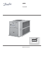
AR05
Control
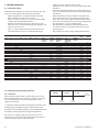
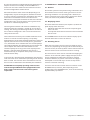
Operation instructions
\\MAINMENU\STATUS
Circuit B Total Capacity
CAPB_T 0 %
DEM_LIM 100 %
SP 4.2 °C
CTRL_PNT -28.9 °C
EMSTOP dsable
ENTER
START/STOP

2
Reglermanual - VMGFF102
The cover graphics are solely for illustration and forms no part of any off er for sale or any sale contract. The
manufacturer reserves the right to change the design at any time without notice.
Contents
1 SAFETY CONSIDERATIONS .................................................................................................................................................3
1.1 - General ..............................................................................................................................................................................................................................3
1.2 - Avoid electrocution.......................................................................................................................................................................................................3
2 GENERAL DESCRIPTION ......................................................................................................................................................3
2.1 - General ..............................................................................................................................................................................................................................3
2.2 - Abbreviations used .......................................................................................................................................................................................................3
3 HARDWARE DESCRIPTION ..................................................................................................................................................3
3.1 - General ..............................................................................................................................................................................................................................3
3.2 - Electrical supply to boards .........................................................................................................................................................................................4
3.3 - Light emitting diodes on boards..............................................................................................................................................................................4
3.4 - The sensors .......................................................................................................................................................................................................................4
3.5 - The controls .....................................................................................................................................................................................................................4
3.6 - Connections at the user terminal block ................................................................................................................................................................4
4. SETTING UP CONTROL SYSTEM ..........................................................................................................................................6
4.1 - General features .............................................................................................................................................................................................................6
4.2 - Default screen characteristics ...................................................................................................................................................................................6
4.3 - Password screens ...........................................................................................................................................................................................................6
4.4 - Menu screen characteristics ......................................................................................................................................................................................7
4.5 - Data screen or confi gurable parameter characteristics ...................................................................................................................................7
4.6 - Parameter modifi cation ...............................................................................................................................................................................................7
4.7 - Operating mode screen ...............................................................................................................................................................................................8
4.8 - Menu tree structure ......................................................................................................................................................................................................9
4.9 - Detailed menu description .................................................................................................................................................................................... .10
5 CONTROL OPERATION .......................................................................................................................................................18
5.1 - Start/stop control....................................................................................................................................................................................................... .18
5.2 - Heating/cooling/standby operation ................................................................................................................................................................... .18
5.3 - Heat exchanger water pump control ..................................................................................................................................................................19
5.4 - Control interlock contact ........................................................................................................................................................................................ .19
5.5 - Heat exchanger frost protection .......................................................................................................................................................................... .19
5.6 - Control point ............................................................................................................................................................................................................... .20
5.7 - Demand limit ............................................................................................................................................................................................................... .20
5.8 - Night mode .................................................................................................................................................................................................................. .20
5.9 - Capacity control ......................................................................................................................................................................................................... .21
5.10 - Head pressure control ........................................................................................................................................................................................... .21
5.11 - Defrost function ....................................................................................................................................................................................................... .21
5.12 - Desuperheater option ........................................................................................................................................................................................... .21
5.13 - Additional electric heater stage control ......................................................................................................................................................... .21
5.14 - Control of a boiler ................................................................................................................................................................................................... .21
5.15 - Master/slave assembly .......................................................................................................................................................................................... .21
6 DIAGNOSTICS TROUBLESHOOTING ..............................................................................................................................22
6.1 - General .......................................................................................................................................................................................................................... .22
6.2 - Displaying alarms ...................................................................................................................................................................................................... .22
6.3 - Resetting alarms ......................................................................................................................................................................................................... .22
6.4 - Alarm codes ................................................................................................................................................................................................................. .23

3
Reglermanual - VMGFF102
1 SAFETY CONSIDERATIONS
1.1 - General
Installation, start-up and servicing of equipment can be
hazardous if certain factors particular to the installation are not
considered: operating pressures, presence of electrical
components and voltages and the installation site (elevated
plinths and built-up up structures). Only properly qualifi ed
installation engineers and highly qualifi ed installers and
technicians, fully trained for the product, are authorised to
install and start-up the equipment safely. During all servic-
ing operations all instructions and recommendations which
appear in the installation and service instructions for the
product, as well as on tags and labels fi xed to the equipment
and components and accompanying parts supplied sepa-
rately, must be read, understood and followed.
• Apply all standard safety codes and practices.
• Wear safety glasses and gloves.
• Use the proper tools to move heavy objects. Move units
carefully and set them down gently.
1.2 - Avoid electrocution
Only personnel qualifi ed in accordance with IEC (Inter-
national Electrotechnical Commission) recommendations
may be permitted access to electrical components. It is
particularly recommended that all sources of electricity to
the unit be shut off before any work is begun. Shut off the
main power supply at the main circuit breaker or isolator.
IMPORTANT: This equipment conforms to all applicable
codes regarding electromagnetic compatibility.
2 GENERAL DESCRIPTION
2.1 - General
An electronic control system is used to regulate the AR05
units.
These units have one or two refrigerant circuits.
Controls:
• compressor start-up to control the water loop
• the fans to optimise operation of each refrigerant circuit
• the defrost cycles to ensure the operation of the
refrigerant circuits.
As standard the control system off ers three on/off
commands:
• Local - on/off command using the keyboard
• Remote - wired on/off command using volt-free
contacts
• Network - Comfort Network (CCN) on/off command.
The command type is selected in advance by keyboard.
2.2 - Abbreviations used
In this manual, the refrigerant circuits are called circuit A and
circuit B. The compressors in circuit A are labelled A1, A2 and
A3. Those in circuit B are B1 and B2.
The following abbreviations are used frequently:
CCN Comfort Network
LED Light Emitting Diode
LEN Internal communication bus linking the main
board to the slave boards
SCT Saturated condensing temperature
SST Saturated suction temperature
EXV Electronic expansion valve
PD-AUX Auxiliary input/output board
3 HARDWARE DESCRIPTION
3.1 - General
The control system consists of an NRCP2-BASE board for
single-circuit units (up to two compressors) and two NRCP2-
BASE boards (one master and one slave board) for units with
three or four compressors. The heat pump units that are
equipped with the additional electric heater stage option
uses an additional PD-AUX board.
All boards communicate via an internal LEN bus. The NRCP2-
BASE boards continuously manage the information received
from the various pressure and temperature probes. The
NRCP2-BASE master board contains the program that
controls the unit.
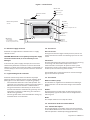
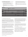
The user interface includes an alphanumeric eight-line
display, two LEDs with fi ve navigation keys as well as a
contrast control wheel.

4
Reglermanual - VMGFF102
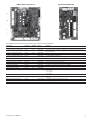
Figure 1 - Control board
3.2 - Electrical supply to boards
All boards are supplied from a common 24 V a.c. supply
referred to earth.
CAUTION: Maintain the correct polarity of the power supply
connection of the boards, to ensure that they are not
damaged.
In the event of a power supply interrupt, the unit restarts
automatically without the need for an external command.
However, any faults active when the supply is interrupted are
saved and may in certain cases prevent a circuit or unit from
restarting.
3.3 - Light emitting diodes on boards
All boards continuously check and indicate the proper
operation of their electronic circuits. A light emitting diode
(LED) lights on each board when it is operating properly.
• The red LED that fl ashes for a two-second period - one
second on, one second off - indicates correct operation. A
diff erent rate indicates a board or a software failure.
• The green LED fl ashes continuously on all boards to
show that the board is communicating correctly over its
internal bus. If the LED is not fl ashing, this indicates a
LEN bus wiring problem.
• The orange LED of the master board fl ashes during any
communication via the CCN bus.
3.4 - The sensors
Pressure sensors
Two types of electronic (high and low-pressure) sensors are
used to measure the suction and discharge pressure in each
circuit.
Thermistors
The heat exchanger water sensors are installed in the enter-ing
and leaving side. The outdoor temperature sensor is
mounted under a metal plate. An optional water system
temperature sensor can be used for master/slave assembly
control (in the case of leaving water control).
In heat pump units a sensor placed on an air heat exchanger
pipe ensures defrost operation.
3.5 - The controls
Water circulation pump
The controller can regulate one or two water heat exchanger
pumps and takes care of automatic change-over between
pumps.
Heaters
They protect the heat exchanger (and the piping for units
without pump) against frost, if the unit has stopped and is
left energised.
Boiler
This output authorises start/stop of a boiler.
3.6 - Connections at the user terminal block
3.6.1 - General description
The contacts below are available at the user terminal block
on the NRCP2-BASE boards. Some contacts can only be used
if the unit operates in remote operating type (Remote).
\\MAINMENU\STATUS
Circuit B Total Capacity
CAPB_T 0 %
DEM_LIM 100 %
SP 4.2 °C
CTRL_PNT -28.9 °C
EMSTOP dsable
ENTER
START/STOP
Contrast control
wheel
Back to the previous
screen
On/off key
- Unit stopped
- List of available operating
modes (only in local mode)
Green LED
Unit has stopped
Unit starts up
Unit in operation
Red LED
No alarm
Warning
Circuit or complete unit error
Up/Down key
- Navigation
- Modifi cation
Enter key
- Validation
- Selection access

5
Reglermanual - VMGFF102
Description Connector/
channel
Terminal Board Remarks
Contact 1: Start/stop J4/CH 8 32-33 NRCP2-BASE Used with the remote operating mode (Remote).
Contact 2: Heating/cooling selection J4/CH 9 63-64 NRCP2-BASE Used with the remote operating mode (Remote) in accordance with the boiler or heat
pump confi guration
Contact 3: Demand limit selection 1 J4/CH 10 73-74 NRCP2-BASE
Customer safety loop input J4/CH 11A 34-35 NRCP2-BASE
Contact 3 bis: Demand limit selection
2
J5/CH 12 NRCP2-BASE Unit without NRCP2-SLAVE board.
Setpoint selection J5/CH 13 NRCP2-BASE Used with the remote operating mode (Remote), unit without NRCP2-SLAVE board.
Desuperheater contact J5/CH14 NRCP2-BASE Used on units with desuperheater
Heat exchanger heater command J2B/CH 21 NRCP2-BASE Frost protection, when the unit is stopped.
Command, water pump 1 J2B/CH 22 NRCP2-BASE
Command, water pump 2 J2B/CH 23 NRCP2-BASE The change-over between the two pumps is confi gurable
Alarm relay output J3/CH 24 30A-31A NRCP2-BASE
Unit operation relay output J3/CH 25 37-38 NRCP2-BASE
CCN network connection J12 NRCP2-BASE RS-485 series connection
- Pin 1: signal +
- Pin 2: ground
- Pin 3: signal -
Setpoint selection J4/CH 8 65-66 NRCP2-SLAVE Used with the remote operating mode (Remote), unit with NRCP2-SLAVE board.
Contact 3 bis: Demand limit selection
2
J4/CH 10 75-76 NRCP2-SLAVE Used with the remote operating mode (Remote), use of NRCP2-SLAVE board, depending
on the size
Relay output for boiler command J3/CH 25 NRCP2-SLAVE Use of NRCP2-SLAVE board, depending on the size
Triac output for boiler command J2B/CH 20 NRCP2-BASE Cooling only unit without NRCP2-SLAVE board
Triac output for boiler command J3/CH 5 PD-AUX Heat pump unit without NRCP2-SLAVE board
The following table summarises the connections at the user terminal block.
NRCP2-BASE control board Optional PD-AUX board
J2A
J2B
J3
J4
J12
J3

6
Reglermanual - VMGFF102
3.6.2 - Volt-free contact on/off /cooling/heating
If the unit works in the remote operating mode (Remote) and
the automatic heating/cooling changeover function is not
selected and if the user confi guration allows this (heat pump
and interface selection) the operation of the on/off contacts
and the heating/cooling contacts is as follows:
Without multiplexing
Off On cooling On heating
On/off contact Open Closed Closed
Heaing/cooling contact - Open Closed
With multiplexing
Off On cooling On heating On auto
On/off contact Open Closed Closed Open
Heaing/cooling contact Open Open Closed Closed
NOTE: The automatic changeover function (on auto)
selects the cooling or heating mode based on the outdoor
temperature (see chapter 5.2).
3.6.3 - Volt-free setpoint selection contact
Cooling Heating
csp 1 csp 2 hsp 1 hsp 2
Set point selection contact Open Closed Open Closed
3.6.4 - Volt-free demand limit selection contact
100% Limit 1 Limit 2 Limit 3
Demand limit 1 Open Closed Open Closed
Demand limit 2 Open Open Closed Closed
4. SETTING UP CONTROL INTERFACE
4.1 - General features
The interface includes diff erent screens that are listed below:
• Default screens with direct display of the main
parameters,
• Menu screens for navigation,
• Data/confi guration screens listing the parameters by
type,
• Operating mode selection screen,
• Password entry screen,
• Parameter modifi cation screen.
NOTE: If the interface is not used for a long period, it will go
black. The control is always active, the operating mode
remains unchanged. The interface screen is re-animated,
when the user presses a key. Pressing the key once illumi-
nates the screen, pressing the key a second time leads to a
screen that is related to the context and the key symbol.
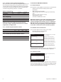
4.2 - Default screen characteristics
There are four default screens. Each screen shows:
• The unit status, its screen number,
• Three displayed parameters.
LOCAL OFF 1 On the left the unit status, on the right
the screen number
Entering water temp Description of the fi rst parameter
EWT 17.2 °C Abbreviation and value with unit of
measurement of the fi rst parameter
Leaving water temp Description of the second parameter
LWT 17.2 °C Abbreviation and value with unit of
measurement of the second parameter
Outside air temperature Description of the third parameter
OAT 21.7 °C Abbreviation and value with unit of
measurement of the third parameter
Pressing the Up or Down key changes one default screen to
another default screen. The screen number is updated.
4.3 - Password screens
Enter password Description of the password entry
screen
0_** Password value
(0 = basic access) Description
The password is entered digit by digit. The cursor is shown at
the current digit that fl ashes. The arrow keys modify the digit
value. The digit modifi cation is validated with the Enter key
and the cursor is moved to the next digit.

7
Reglermanual - VMGFF102
Enter password
1_** The fi rst digit is 1, the cursor is
positioned on the second digit
(0 = basic access)
Enter password
11_**
(
0 = basic access)
Pressing the Enter key at a digit without value validates the
overall selection of the password. The screen is refreshed by
the menu list, and the items displayed depend on the level of
the activated password.
The entry of an incorrect password keeps the password entry
screen.
Password selection 0 (zero) can simply be made by pressing
the Enter key twice in succession.
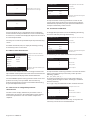
4.4 - Menu screen characteristics
\\MAINMENU Current path in the menu structure
GENUNIT PUMPSTAT Selection cursor to the left of the fi rst
column
TEMP RUNTIME
PRESSURE MODES Menu list
SETPOINT LOGOUT
INPUTS
OUTPUTS
General Parameters Menu Description of the menu framed by the
selection cursor
Each menu item defi nes the access to categorised data. The
Up and Down arrows position the cursor at the current item. The
Enter key activates the display of the selected sub-menu.
The item LOGOUT permits exiting from the menu screen and
protects access by a user password. The “Previous” key
permits exiting from the current screen without deactivating
the password-protected access.
4.5 - Data screen or confi gurable parameter
characteristics
The data screens display information parameters such as
temperatures or pressures. The confi guration screens display
unit control parameters such as the water temperature
setpoints.
\\MAINMENU\TEMP Current path in the menu structure
EWT 12.0°C List of items
LWT 7.0°C Cursor position
OAT 35.0°C
CHWSTEMP -17.8°C
SCT_A 57.0°C
Leaving Water Temperature Description of the item framed by the
selection cursor
The Up and Down arrow keys position the cursor on the
current menu item. The Enter key activates the parameter
modifi cation (if possible). Any non-pertinent modifi cation
attempt is blocked by a refusal screen.
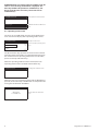
4.6 - Parameter modifi cation
A confi guration parameter can be modifi ed by positioning
the cursor and then pressing the Enter key.
\\MAINMENU\SETPOINT Current path in the menu structure
cps1 4.0°C List of items
cps2 7.0°C Cursor position
hps1 38.0°C
hps2 38.0°C
hramp_sp 27.4°C
Cooling Setpoint 2 Description of the item framed by the
selection cursor
The following screen allows modifi cation of a parameter.
Modify value Screen description
csp 2
7.0 °C Current value
_ °C Cursor position
Cooling Setpoint 2 Item description
The Up and Down arrow keys permit the selection of the fi rst
digit. Pressing the Up key successively scrolls up to the
following symbols:
0, 1, 2, 3, 4, 5, 6, 7, 8, 9, ., -.
The Down key follows the reverse order of the Up key in
scrolling down the digit list above. Each digit is validated
with the Enter key.
The - sign is only accessible for the fi rst selected character.
Modify value Description of the screen
csp 2
7.0 °C Current value
6.5_ °C New value before validation
Cooling Setpoint 2 Item description
The value is validated with the Enter key. At any time the
return key cancels the current modifi cation.

8
Reglermanual - VMGFF102
ATTENTION: If the user exits from the current data screen, the
value is saved. A saving confi rmation is displayed. The
Enter key validates the parameter modifi cation(s). The
Return to the Previous Screen key cancels the current
modifi cation(s).
\\MAINMENUSETPOINT Current path in the menu structure
Save changes? Confi rmation that the modifi cation is
saved
4.7 - Operating mode screen
The unit is in Local Off mode, pressing the on/off (0/1) key
once activates the display of the operating mode screen.
Select Machine Mode Description of the screen
Local On List of the machine operating modes
Local Schedule Cursor
CCN
Remote
The Up and Down keys position the cursor on the selected
operating mode. Four modes are immediately displayed on
the screen. To access operating modes that are not visible,
please use the Up and Down keys.
When the operating mode has been selected, the new
operating mode can be validated with the Enter key.
Command accepted Operating mode validation screen
When the unit is in an operating mode and the On/off key is
pressed, the unit will stop. A confi rmation screen protects the
unit against inadvertent shutdowns.
PRESS ENTER Machine shutdown confi rmation
screen
TO CONFIRM STOP

9
Reglermanual - VMGFF102
4.8 - Menu tree structure
GENUNIT
TEMP
PRESSURE
SETPOINT
INPUTS
OUTPUTS
PUMPSTAT
RUNTIME
MODES
ALARMS
CONFIG
LOGOUT
ALARMRST
CUR_ALRM
ALMHIST1
GENCONF
PUMPCONF
HCCONFIG
RESETCFG
USERCONF
SCHEDULE
HOLIDAY
BRODCAST
DATETIME
DISPLAY
HOLIDY01S
HOLIDY16S
HOLIDY02S
…
OCC1P01S
OCC1P02S
GENUNIT
TEMP
PRESSURE
SETPOINT*
INPUTS
OUTPUTS
PUMPSTAT
RUNTIME
MODES
ALARMS*
CONFIG
LOGOUT
ALARMRST
CUR_ALRM
ALMHIST1
GENCONF
PUMPCONF
HCCONFIG
RESETCFG
USERCONF
SCHEDULE
HOLIDAY
BRODCAST
DATETIME
CTRL_ID
HOLIDY01S
HOLIDY16S
HOLIDY02S
…
OCC1P01S
OCC1P02S
NAVIGATION
Password = "0"
ACCESS
ALL
USER
DEFAULT
SCREENS
PASSWORD
General parameters
Temperatures
Pressures
Setpoint
Inputs
Outputs
Pump status
Operating time
Unit status
Alarms menu
Confi guration menu
Disconnection
Reset of the alarms
Current alarm
Alarm history
Time schedule
Holidays
General confi guration
Pump confi guration
Heating/cooling
confi guration
Setpoint reset
User confi guration
Broadcast
Date and time
Identifi cation control
SHUTDOWN
CONFIRMATION
SCREEN
LIST OF OPERATING
MODES
(for main
interface only)
Schedule 1
Schedule 2
Holidays 1
Holidays 2
Holidays 16
* Confi gurable from the GENCONF menu

10
Reglermanual - VMGFF102
4.9 - Detailed menu description
ATTENTION: Depending on the unit characteristics, certain menu items are not used.
4.9.1 - GENUNIT menu
NAME FORMAT UNIT DESCRIPTION
ctrl_typ 0/1/2 - Local = 0. CCN = 1. Remote = 2
STATUS Running/Off /Stopping/
Delay
- Operating status
ALM Normal/Partial/Shutdown - Alarm status
min_left 0-15 min Start-up delay
HEATCOOL Heat/Cool/Standby/Both - Heating/cooling status
LOCAL_HC 0/1/2 - Heating/cooling selection via the main interface
HC_SEL 0/1/2 - Heating/cooling selection via the CCN network
0 = cooling, 1 = heating, 2 = auto
LSP_SEL 0/1/2 - Setpoint selection via the main interface
SP_SEL 0/1/2 - Setpoint selection via the CCN network
0 = Auto 1 = Spt1 2 = Spt2
SP_OCC Yes/No - Occupied setpoint active
CHIL_S_S Enable/Disable - Unit start/stop via the CCN network
CHIL_OCC Yes/No - Unit time schedule via the CCN network
CAP_T nnn % Total unit capacity
CAPA_T nnn % Capacity circuit A
CAPB_T nnn % Capacity circuit B
DEM_LIM nnn % Demand limit value
SP ±nnn.n °C Current setpoint
CTRL_PNT ±nnn.n °C Control point
EMSTOP Enable/Emstop - CCN emergency stop
4.9.2 - TEMP menu
NAME FORMAT UNIT DESCRIPTION
EWT ±nnn.n °C Heat exchanger entering water temperature
LWT ±nnn.n °C Heat exchanger leaving water temperature
OAT ±nnn.n °C Outside air temperature
CHWSTEMP ±nnn.n °C Common master/slave temperature
SCT_A ±nnn.n °C Saturated condensing temperature A
SST_A ±nnn.n °C Saturated suction temperature A
SCT_B ±nnn.n °C Saturated condensing temperature B
SST_B ±nnn.n °C Saturated suction temperature B
DEFRT_A ±nnn.n °C Defrost temperature A
DEFRT_2 ±nnn.n °C Defrost temperature B or second coil
sgtc1 ±nnn.n °C Suction gas temperature, coil 1, unit with three compressors
sgtc2 ±nnn.n °C Suction gas temperature, coil 2, unit with three compressors
4.9.3 - PRESSURE menu
NAME FORMAT UNIT DESCRIPTION
DP_A ±nnn.n kPa Discharge pressure A
SP_A ±nnn.n kPa Suction pressure A
DP_B ±nnn.n kPa Discharge pressure B
SP_B ±nnn.n kPa Suction pressure B
4.9.4 - SETPOINT menu
NAME FORMAT VALUE UNIT DESCRIPTION
csp1 - 29.7 to 20 7.0 °C Cooling setpoint 1
csp2 - 29.7 to 20 7.0 °C Cooling setpoint 2
hsp1 20 to 55 38.0 °C Heating setpoint 1
hsp2 20 to 55 38.0 °C Heating setpoint 2
hramp_sp 0.1 to 1.1 0.60 ^C Ramp loading
cauto_sp 3.9 to 50 24.0 °C Cooling change-over setpoint
hauto_sp 0 to 46.1 18.0 °C Heating change-over setpoint
lim_sp1 0 to 100 100 % Limit setpoint 1
lim_sp2 0 to 100 100 % Limit setpoint 2
lim_sp3 0 to 100 100 % Limit setpoint 3
min_sct 26.7 to 55* 40 °C Condensing setpoint for desuperheater option
* 50, if the unit includes a variable-speed fan

11
Reglermanual - VMGFF102
4.9.5 - INPUTS menu
NAME FORMAT UNIT DESCRIPTION
ONOFF_SW Open/Close - Remote start/stop contact
HC_SW Open/Close - Remote heating/cooling contact
on_ctrl Off , On Cool, On Heat, On
Auto
- Current control
SETP_SW Open/Close - Remote setpoint contact
LIM_SW1 Open/Close - Remote demand limit contact 1
LIM_SW2 Open/Close - Remote demand limit contact 2
FLOW_SW Open/Close - Water fl ow rate/customer safety loop contact
leak_1_v nn.n Volt Leak detector value 1
leak_2_v nn.n Volt Leak detector value 2
DSHTR_SW Open/Close - Desuperheater user contact
4.9.6 - OUTPUTS menu
NAME FORMAT UNIT DESCRIPTION
CP_A1 On/Off - Compressor output A1
CP_A2 On/Off - Compressor output A2
CP_A3 On/Off - Compressor output A3
fan_a1 0-2 - Fan output A1
fan_a2 0-2 - Fan output A2
exv_a 0-100 % EXV position circuit A
HD_POS_A 0-100 % Position variable fan speed controller A
RV_A On/Off - Four-way refrigerant valve
CP_B1 On/Off - Compressor output B1
CP_B2 On/Off - Compressor output B2
fan_b1 0-2 - Fan output B1
exv_a 0-100 % EXV position circuit B
HD_POS_B 0-100 % Position variable fan speed controller B
RV_B On/Off - Four-way refrigerant valve
C_HEATER On/Off - Heat exchanger and lower coil heater
BOILER On/Off - Boiler output
EHS_STEP 0-4 - Electric heater stages
ALARM On/Off - Alarm relay
RUNNING On/Off - Unit on relay
4.9.7 - PUMPSTAT menu
NAME FORMAT UNIT DESCRIPTION
CPUMP_1 On/Off - Command pump 1
CPUMP_2 On/Off - Command pump 2
ROT_PUMP Yes/No - Pump rotation
WATPRES1 ±nnn.n kPa Water pressure sensor 1
WATPRES2 ±nnn.n kPa Water pressure sensor 2
WP_CALIB Yes/No - Water pressure sensor calibration?
Following a water pressure sensor error, WP_OFFST is deconfi gured (-99 kPa) to inform of
the need to calibrate the water loop. This calibration must be made while there is no water
fl ow in the machine
WP_OFFST ±nnn.n kPa Water pressure sensor calibration value
DP_FILTR nnn.n kPa Filter pressure drop
WP_MIN nnn.n kPa Minimum water pressure
WAT_FLOW ±nnn.n g/s Water fl ow rate
CAPPOWER ±nnn.n kW Unit capacity
w_dt_spt nn.n ^C Setpoint delta T
w_dp_spt nn.n kPa Setpoint delta P
drvp_pwr +nnn.n kW Pump capacity
drvp_i +nnn.n A Pump current
drvp_ver xxxxxxxx - Variable pump speed controller version

12
Reglermanual - VMGFF102
4.9.8 - RUNTIME menu
NAME FORMAT UNIT DESCRIPTION
HR_MACH nnnnn hours Unit operating hours
st_mach nnnnn - Number of start-ups, unit
HR_CP_A1 nnnnn hours Operating hours compressor A1
st_cp_a1 nnnnn - Number of start-ups compressor A1
HR_CP_A2 nnnnn hours Operating hours compressor A2
st_cp_a2 nnnnn - Number of start-ups compressor A2
HR_CP_A3 nnnnn hours Operating hours compressor A3
st_cp_a3 nnnnn - Number of start-ups compressor A3
HR_CP_B1 nnnnn hours Operating hours compressor B1
st_cp_b1 nnnnn - Number of start-ups compressor B1
HR_CP_B2 nnnnn hours Operating hours compressor B2
st_cp_b2 nnnnn - Number of start-ups compressor B2
hr_fana1 nnnnn hours Operating hours fan A1
hr_fana2 nnnnn hours Operating hours fan A2
hr_fanb1 nnnnn hours Operating hours fan B1
st_fa_a1 nnnnn - Number of start-ups fan A1
st_fa_a2 nnnnn - Number of start-ups fan A2
st_fa_b1 nnnnn - Number of start-ups fan B1
hr_cpum1 nnnnn hours Operating hours pump 1
hr_cpum2 nnnnn hours Operating hours pump 2
nb_def_a nnnnn - Number of defrost cycles circuit B
nb_def_b nnnnn - Number of defrost cycles circuit A
4.9.9 - MODES menu
NAME FORMAT UNIT DESCRIPTION
m_limit Yes/No - Demand limit active
m_ramp Yes/No - Ramp loading active
m_cooler Yes/No - Heat exchanger heater active
m_night Yes/No - Low-noise level night mode
m_SM Yes/No - Aquasmart active
m_leadla Yes/No - Master/slave active
m_auto Yes/No - Change-over active
m_heater Yes/No - Electric heater stages active
m_lo_ewt Yes/No - Lock heating mode and entering water too cold
m_boiler Yes/No - Boiler active
m_defr_a Yes/No - Defrost circuit A active
m_defr_b Yes/No - Defrost circuit B active
m_sst_a Yes/No - Low suction temperature circuit A
m_sst_b Yes/No - Low suction temperature circuit B
m_dgt_a Yes/No - High discharge gas temperature circuit A
m_dgt_b Yes/No - High discharge gas temperature circuit B
m_hp_a Yes/No - High pressure circuit A
m_hp_b Yes/No - High pressure circuit B
m_sh_a Yes/No - Low superheat circuit A
m_sh_b Yes/No - Low superheat circuit B

13
Reglermanual - VMGFF102
4.9.10 - ALARMS menu
NAME DESCRIPTION
ALARMRST Alarm reset
CUR_ALRM Current alarms
ALMHIST1 Alarm history
4.9.11 - CONFIG menu
NAME DESCRIPTION
GEN_CONF General confi guration menu
PUMPCONF Water pump confi guration menu
HC_CONFIG Heating/cooling confi guration menu
RESETCFG Reset confi guration menu
USERCONFIG User confi guration menu
SCHEDULE Time schedule
HOLIDAY Holiday calendar
BRODCAST Broadcast menu
DATETIME Date and time menu
DISPLAY Display confi guration menu
CTRL_ID Identifi cation control
4.9.12 - ALARMRST menu
NAME FORMAT UNIT DESCRIPTION
RESET_AL Normal - Alarm reset
ALM Normal - Alarm status
alarm_1c nnnnn - Current alarm 1
alarm_2c nnnnn - Current alarm 2
alarm_3c nnnnn - Current alarm 3
alarm_4c nnnnn - Current alarm 4
alarm_5c nnnnn - Current alarm 5
alarm_1 nnnnn - Current JBus alarm 1
alarm_2 nnnnn - Current JBus alarm 2
alarm_3 nnnnn - Current JBus alarm 3
alarm_4 nnnnn - Current JBus alarm 4
alarm_5 nnnnn - Current JBus alarm 5
4.9.13 - CUR_ALRM menu
This menu lists up to ten a active alarms. For each alarm the
display shows the time and date the alarm was generated as
well as the alarm description. Each screen shows one alarm.
…\ALARMS\CUR_ALM
HH:MM DD-MM-YY: alarm text
Alarm #1
4.9.14 - ALMHIST1 menu
This menu lists up to twenty alarms that have occurred at the
unit. For each alarm the display shows the time and date the
alarm was generated as well as the alarm description. Each
screen shows one alarm.
…\ALARMS\ALMHIST1
HH:MM DD-MM-YY: alarm text
Alarm #1

14
Reglermanual - VMGFF102
4.9.15 - SCHEDULE menu
NAME DESCRIPTION
OCC1P01S Unit on/off time schedule
OCC1P02S Unit setpoint selection time schedule
4.9.16 - HOLIDAY menu
NAME DESCRIPTION
HOLDY_01 Holiday period 1
HOLDY_02 Holiday period 2
HOLDY_03 Holiday period 3
HOLDY_04 Holiday period 4
HOLDY_05 Holiday period 5
HOLDY_06 Holiday period 6
HOLDY_07 Holiday period 7
HOLDY_08 Holiday period 8
HOLDY_09 Holiday period 9
HOLDY_10 Holiday period 10
HOLDY_11 Holiday period 11
HOLDY_12 Holiday period 12
HOLDY_13 Holiday period 13
HOLDY_14 Holiday period 14
HOLDY_15 Holiday period 15
HOLDY_16 Holiday period 16
4.9.17 - BRODCAST menu
NAME FORMAT DEFAULT UNIT DESCRIPTION
CCNbroad 0/1/2 2 - Activates the broadcast
0 = deactivated, 1= broadast during holidays at the network, 2 =
broadcast during holidays, machine only
oatbusnm 0 to 239 0 - Broadcast of the outside temperature
Bus number of the machine with the outside temperature
oatlocad 0 to 239 0 - Element number of the machine with the outside temperature
dayl_sel Disable/Enable Disable - Activation summer time, winter time
Summer time
startmon 1 to 12 3 - Month
startdow 1 to 7 7 - Day of the week (1 = Monday)
startwom 1 to 5 5 - Week of the month
Winter time
stopmon 1 to 12 10 - Month
stoptdow 1 to 7 7 - Day of the week (1 = Monday)
stopwom 1 to 5 5 - Week of the month
4.9.18 - GENCONF menu
NAME FORMAT DEFAULT UNIT DESCRIPTION
lead_cir 0/1/2 0 - Circuit loading sequence
0 = auto, 1 = A fi rst, 2 = B fi rst
seq_typ No/Yes No - Loading sequence by circuit
ramp_sel No/Yes No - Ramp loading sequence
off _on_d 1 to 15 1 min Start-up delay
nh_limit 0 to 100 100 % Capacity limitation in night mode
nh_start 00:00 to 24:00 00:00 - Night mode start hour
nh_end 00:00 to 24:00 00:00 - Night mode stop hour
bas_menu 0 to 3 0 - Basic menu confi guration
0 = total access
1 = access to the alarm menu by password
2 = access to the setpoint menu by password
3 = combination of 1 and 2
synoptic No/Yes No - Synoptic diagram displayed
4.9.19 - PUMPCONF menu
NAME FORMAT DEFAULT UNIT DESCRIPTION
pump_seq 0/1/2/3/4 0 - Heat exchanger pump sequence
0 = no pump
1 = one pump
2 = two pumps auto
3 = pump 1 manual
4 = pump 2 manual
pump_del 24 to 3000 48 hours Rotation time between pumps
pump_per No/Yes No - Pump seizure protection
pump_sby No/Yes No - Pump shutdown when the unit is in standby
pump_loc No/Yes Yes - Flow rate verifi cation when the pump has shut down

15
Reglermanual - VMGFF102
4.9.20 - HCCONFIG menu
NOM FORMAT DEFAULT UNIT DESCRIPTION
auto_sel No/Yes No - Automatic change-over selection
cr_sel 0 to 2 0 - Cooling reset selection
hr_sel 0 to 2 0 - Heating reset selection
1 = outside temp., 0 = none, 2 = delta T
heat_th -20 to 0 -15 °C Outside temperature threshold cooling mode
boil_th -15 to 15 -10 °C Outside temperature threshold for the boiler
ehs_th -5 to 21.2 5 °C Outside temperature threshold for electric heater stages
both_sel No/Yes No - Heating or cooling command selection for HSM
ehs_back No/Yes No - 1 backup electric heater stage
ehs_pull 0 to 60 0 minutes Delay before start-up of the fi rst electric heater stage
ehs_defr No/Yes No - Quick electric heat stages for defrost
4.9.21 - RESETCFG menu
NAME FORMAT DEFAULT UNIT DESCRIPTION
COOLING RESET
oatcr_no -10 to 51.7 -10 °C Outside temperature for no reset
oatcr_fu -10 to 51.7 -10 °C Outside temperature for maximum reset
dt_cr_no 0 to 13.9 0 ^C Delta T for no reset
dt_cr_fu 0 to 13.9 0 ^C Delta T for maximum reset
cr_deg -16.7 to 16.7 0 ^C Cooling reset value
HEATING RESET
oathr_no -10 to 51.7 -10 °C Outside temperature for no reset
oathr_fu -10 to 51.7 -10 °C Outside temperature for maximum reset
dt_hr_no 0 to 13.9 0 ^C Delta T for no reset
dt_hr_fu 0 to 13.9 0 ^C Delta T for maximum reset
hr_deg -16.7 to 16.7 0 ^C Heating reset value
4.9.22 - USERCONF menu
NAME FORMAT DEFAULT UNIT DESCRIPTION
language 0 to 4 0 - Language selection
English = 0, Spanish = 1, French = 2, Portuguese = 3, Italian = 4,
Translation = 5
use_pass 1 to 9999 11 - User password
4.9.23 - DATETIME menu
NAME FORMAT DEFAULT UNIT DESCRIPTION
hour 0 to 24 hours Hour
minutes 0 to 59 minutes Minutes
dow 1 to 7 Day of the week
tom_hol No/Yes No - Holiday tomorrow?
tod_hol No/Yes No - Holiday today
dlig_off No/Yes - Winter time change-over active?
dlig_on No/Yes - Summer time change-over active?
d_of_m 1 to 31 Day of the month
month 1 to 12 Month
year 0 to 99 Year
4.9.24 - Menu CTRL_ID
NAME FORMAT DEFAULT UNIT DESCRIPTION
elemt_nb 1 to 239 1 - Element number
bus_nb 0 to 239 0 - Bus number
baudrate 9600 to 38400 9600 - Communication speed
AR05 Description
CSA-SR-20H430NN
-
Software version
Serial number

16
Reglermanual - VMGFF102
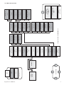
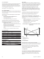
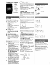
4.9.25 - OCC1PSX menu
The control provides two timer programs: schedule 1 and
schedule 2 that can be activated.
The fi rst timer program (schedule 1) provides a means to
automatically switch the unit from an occupied mode to an
unoccupied mode: the unit is started during occupied periods.
The second timer program (schedule 2) provides a means to
automatically switch the active setpoint from an occupied
setpoint to an unoccupied setpoint: cooling setpoint 1 is
used during occupied periods, cooling or heating setpoint 2
during unoccupied periods.
Each schedule consists of eight time periods set by the
operator. These time periods can be fl agged to be in eff ect or
not in eff ect on each day of the week plus a holiday period.
The day begins at 00.00 hours and ends at 23.59 hours.
Program is in unoccupied mode unless a schedule time period is
in eff ect. If two periods overlap and are both active on the
same day, the occupied mode takes priority over the
unoccupied period.
Each of the eight periods can be displayed and changed with
the aid of a sub-sub-menu. The table on page 17 shows how to
access the period confi guration. Method is the same for the
time schedule 1 or the time schedule 2.
Time schedule type:
23
22
21
P6P3
2
0
P3
19
P3
1
8
P3P2P2
17
P4P4P3P2P2
1
6
P4P4P3P2P2
1
5
P4P4P3P2P2
14
P4P4P3P2P2
1
3
P4P4P3P2P2
12
P5P4P4P3P2P2
11
P5P4P4P3P2P2
10
P5P4P4P3P2P2
9
P5P4P4P3P2P2
8
P5P4P4P3P2P2
7
6
5
4
3
P1
2
P1
1
P1
0
HOLSUNSATFRITHUWESTUEMON
Time
MON: Monday
TUE: Tuesday
WED: Wednesday
THU: Thursday
FRI: Friday
SAT: Saturday
SUN: Sunday
HOL: Holiday
Occupied
Unoccupied
Starts at Stops at Active on
P1: period 1, 0h00, 3h00, Monday
P2: period 2, 7h00, 18h00, Monday + Tuesday
P3: period 3, 7h00, 21h00, Wednesday
P4: period 4, 7h00, 17h00, Thursday + Friday
P5: period 5, 7h00, 12h00, Saturday
P6: period 6, 20h00, 21h00, Holidays
P7: period 7, Not used in this example
P8: period 8, Not used in this example
NAME FORMAT DEFAULT UNIT DESCRIPTION
OVR_EXT 0-4 0 hours Occupied schedule override
DOW1 0/1 11111111 - Period 1 day of the week MTWTFSSH
Monday Tuesday Wednesday Thursday Friday Saturday Sunday Holiday
OCCTOD1 0:00-24:00 00:00 - Occupied from
UNOCTOD1 0:00-24:00 24:00:00 - Occupied until
DOW2 0/1 0 - Period 2 days of the week MTWTFSSH
Monday Tuesday Wednesday Thursday Friday Saturday Sunday Holiday
OCCTOD2 0:00-24:00 00:00 - Occupied from
UNOCTOD2 0:00-24:00 00:00 - Occupied until
DOW3 0/1 0 - Period 3 days of the week MTWTFSSH
Monday Tuesday Wednesday Thursday Friday Saturday Sunday Holiday
OCCTOD3 0:00-24:00 00:00 - Occupied from
UNOCTOD3 0:00-24:00 00:00 - Occupied until
DOW4 0/1 0 - Period 4 days of the week MTWTFSSH
Monday Tuesday Wednesday Thursday Friday Saturday Sunday Holiday
OCCTOD4 0:00-24:00 00:00 - Occupied from
UNOCTOD4 0:00-24:00 00:00 - Occupied until
DOW5 0/1 0 - Period 5 days of the week MTWTFSSH
Monday Tuesday Wednesday Thursday Friday Saturday Sunday Holiday
OCCTOD5 0:00-24:00 00:00 - Occupied from
UNOCTOD5 0:00-24:00 00:00 - Occupied until
DOW6 0/1 0 - Period 6 days of the week MTWTFSSH
Monday Tuesday Wednesday Thursday Friday Saturday Sunday Holiday
OCCTOD6 0:00-24:00 00:00 - Occupied from
UNOCTOD6 0:00-24:00 00:00 - Occupied until
DOW7 0/1 0 - Period 7 days of the week MTWTFSSH
Monday Tuesday Wednesday Thursday Friday Saturday Sunday Holiday
OCCTOD7 0:00-24:00 00:00 - Occupied from
UNOCTOD7 0:00-24:00 00:00 - Occupied until
DOW8 0/1 0 - Period 8 days of the week MTWTFSSH
Monday Tuesday Wednesday Thursday Friday Saturday Sunday Holiday
OCCTOD8 0:00-24:00 00:00 - Occupied from
UNOCTOD8 0:00-24:00 00:00 - Occupied until

17
Reglermanual - VMGFF102
4.9.26 - HOLIDY0XS menu
This function is used to defi ne 16 public holiday periods.
Each period is defi ned with the aid of three parameters: the
month, starting day and duration of the public holiday
period. During these public holidays the controller will be in
occupied or unoccupied mode, depending on the
programmed periods validated for public holidays.
Each of these public holiday periods can be displayed and
changed with the aid of a sub-menu.
ATTENTION: The broadcast function must be activated to
utilise the holiday schedule, even if the unit is running in
stand-alone mode (not connected to CCN).
NAME FORMAT DEFAULT UNIT DESCRIPTION
HOL_MON 0-12 0 - Holiday month
HOL_DAY 0-31 0 - Holiday day
HOL_LEN 0-99 0 - Holiday duration

18
Reglermanual - VMGFF102
5 CONTROL OPERATION
5.1 - Start/stop control
The table below summarises the unit control type and stop
or go status with regard to the following parameters.
• Operating type: this is selected using the start/stop
button on the front of the user interface.
LOFF: local off , L-C: local on, L-SC: local schedule, REM:
remote, CCN: network, MAST: Master
• Remote start/stop contacts: these contacts are used
when the unit is in remote operating type (Remote). See
sections 3.6.2 and 3.6.3.
• CHIL_S_S: this network command relates to the unit
start/stop when the unit is in network mode (CCN).
• Command set to Stop: the unit is halted.
• Command set to Start: the unit runs in accordance with
schedule 1.
• Start/Stop schedule: occupied or unoccupied status of
the unit as determined by the chiller start/stop program
(Schedule 1).
• Master control type. This parameter is used when the
unit is the master unit in a two chiller lead/lag arrange-
ment. The master control type determines whether the
unit is to be controlled locally, remotely or through CCN
(this parameter is a Service confi guration).
• CCN emergency shutdown: if this CCN command is
activated, it shuts the unit down whatever the active
operating type.
• General alarm: the unit is totally stopped due to failure.
5.2 - Heating/cooling/standby operation
5.2.1 - General
The heating/cooling/standby selection applies to all units.
But only liquid chiller units, controlling a boiler can change
over to heating mode. Heating/cooling control can be
automatic or manual.
In automatic mode the outdoor temperature determines the
heating/cooling/standby changeover based on the two
threshold values confi gured by the user (see RESETCFG menu
for cooling and heating mode changeover thresholds).
If the unit is in standby it does not cool or heat, and no
compressor can be activated. The diagram below summarises
the operating principle in automatic mode.
HEATING STANDBY COOLING
Outdoor
temperature
Heating
threshold*
Cooling
threshold
* This threshold does not apply to cooling only units that do not control a boiler.
ACTIVE OPERATING TYPE STATUS OF PARAMETERS CONTROL
TYPE
UNIT
MODE
LOFF L-ON L-SC rEM CCN MASt CHIL_S_S REMOTE
START/STOP
CONTACT
MASTER
CONTROL
TYPE
START/STOP
SCHEDULE
MODE
CCN
EMERGENCY
SHUTDOWN
GENERAL
ALARM
- - - - - - - - - - Enable - - Off
------- - - - - Yes - Off
Active - - - - - - - - - - - Local Off
- - Active - - - - - - Unoccupied - - Local Off
---Active--- Off - - - - Remote Off
- - - Active - - - - - Unoccupied - - Remote Off
- - - - Active - Disable - - - - - CCN Off
- - - - Active - - - - Unoccupied - - CCN Off
- - - - - Active - - Local Unoccupied - - Local Off
-----Active- Off Remote - - - Remote Off
- - - - - Active - - Remote Unoccupied - - Remote Off
- - - - - Active Disable - CCN - - - CCN Off
- - - - - Active - - CCN Unoccupied - - CCN Off
- Active - - - - - - - - Disable No Local On
- - Active - - - - - - Occupied Disable No Local On
- - - Active - - - On cooling - Occupied Disable No Remote On
- - - Active - - - On heating - Occupied Disable No Remote On
- - - Active - - - On auto - Occupied Disable No Remote On
- - - - Active - Enable - - Occupied Disable No CCN On
- - - - - Active - - Local Occupied Disable No Local On
- - - - - Active - On cooling Remote Occupied Disable No Remote On
- - - - - Active - On heating Remote Occupied Disable No Remote On
- - - - - Active - On auto Remote Occupied Disable No Remote On
- - - - - Active Enable - CCN Occupied Disable No CCN On

19
Reglermanual - VMGFF102
5.3 - Heat exchanger water pump control
The unit can control one or two heat exchanger water pumps.
The pump is turned on when this option is confi gured (see
PUMPCONFIG) and when the unit is in one of the on modes
described above or in delay mode. Since the minimum value for
the delay at start-up is 1 minute (confi gurable between 1 and
15 minutes), the pump will run for at least one minute before
the fi rst compressor starts.
The pump is kept running for 20 seconds after the unit goes to
stop mode. The pump keeps working when the unit switches
from heating to cooling mode or vice-versa. It is turned off if
the unit is shut down due to an alarm unless the fault is a frost
protection error. The pump can be started in particular
operating conditions when the heat exchanger heater is
active (see chapter 5.5). See chapter 5.14 for the particular
heat exchanger pump control for the follower unit (master/
slave assembly).
If two pumps are controlled and the reversing function has
been selected (see PUMPCONF confi guration), the control tries
to limit the pump run time delta to the confi gured pump
change-over delay. If this delay has elapsed, the pump
reversing function is activated, when the unit is running.
During the reversing function both pumps run together for
two seconds. If the pumps are of the variable fl ow rate type
pump reversal will take place at the next machine start-up.
If a pump has failed and a secondary pump is available, the
unit is stopped and started again with this pump.
The control provides a means to automatically start the
pump each day at 14.00 hours for 2 seconds when the unit is
off . If the unit is fi tted with two pumps, the fi rst pump is
started on odd days and the second pump is started on even
days. Starting the pump periodically for few seconds
increases the life-time of the pump bearings and the
tightness of the pump seal.
5.4 - Control interlock contact
This contact checks the status of a loop (water fl ow switch
and customer safety loop, see chapter 3.6). It prevents the
unit from starting if it is open when the delay at start-up has
expired. This open contact leads to an alarm shut-down, if
the unit is running.
5.5 - Heat exchanger frost protection
The heater for the heat exchanger and the water pump (for
units with a pump) can be energised to protect the heat
exchanger, if it may be damaged by frost, when the unit is
shut down for a long time at low outdoor temperature.
NOTE: Heat exchanger heater control parameters can be
modifi ed, using the Service confi guration.
5.2.2 - Heating/cooling/auto selection
The table below summarises the unit heating/cooling opera-
tion, based on the following parameters:
• Control type: indicates whether the unit operates in
local, remote or CCN mode. See section 5.1.
• Unit on/off status: indicates whether the unit is shut
down (not authorised to start) or in operation (or
authorised to start).
• Heating/cooling/auto selection in local mode: operating
mode selected via the user interface. See GENUNIT
menu.
• Remote heating/cooling contacts: these contacts are
only active if the unit is under remote control.
• HC_SEL: this network command permits heating/
cooling/auto control, if the unit is in CCN operating
mode.
• Outside temperature: determines the operation, if the
unit is in automatic heating/cooling/standby changeover
mode.
PARAMETER STATUS
ON/OFF STATUS CONTROL TYPE HEATING/COOLING
SELECTION IN LOCAL
MODE
REMOTE HEATING/
COOLING CONTACTS
HC_SEL OUTDOOR TEMPERATURE OPERATING MODE
Off - - - - - Cooling
On Local Cooling - - - Cooling
On Local Heating - - - Heating
On Local Auto - - > Cooling threshold Cooling
On Local Auto - - < Heating threshold Heating*
On Local Auto - - Between cooling and heating thresholds Standby
On Remote - Cooling mode - - Cooling
On Remote - Heating mode - - Heating
On Remote - Auto mode - > Cooling threshold Cooling
On Remote - Auto mode - < Heating threshold Heating*
On Remote - Auto mode - Between cooling and heating thresholds Standby
On CCN - - Cooling - Cooling
On CCN - - Heating - Heating
On CCN - - Auto > Cooling threshold Cooling
On CCN - - Auto < Heating threshold Heating*
On CCN - - Auto Between cooling and heating thresholds Standby
* Does not apply to cooling only units that do not control a boiler.

20
Reglermanual - VMGFF102
5.6 - Control point
The control point represents the water temperature that the
unit must produce. The heat exchanger entering water
temperature is controlled by default, but the heat exchanger
leaving water temperature can also be controlled (requires a
Service confi guration modifi cation).
Control point = active setpoint + reset
5.6.1 - Active setpoint
Two setpoints can be selected as active in cooling mode and
two in heating mode. Usually, the second setpoint is used for
unoccupied periods.
Depending on the current operating type, the active setpoint
can be selected:
• by choosing the item in the GENUNIT menu,
• via the user’s volt-free contacts,
• via network commands
• via the setpoint timer program (schedule 2).
The following tables summarise the possible selections
depending on the control types (local, remote or network)
and the following parameters:
• Setpoint select in local control: item LSP_SEL in the
GENUNIT menu permits selection of the active set-point,
if the unit is in local operating type.
• Heating/cooling operating mode.
• Setpoint selection contacts: setpoint selection contact
status.
• Schedule 2 status: schedule for setpoint selection.
LOCAL OPERATING MODE
PARAMETER STATUS
Heating/cooling
operating mode
Local setpoint
selection
Time schedule 2
status
Active setpoint
Cooling sp 1 - Cooling setpoint 1
Cooling sp 2 - Cooling setpoint 2
Cooling auto occupied Cooling setpoint 1
Cooling auto unoccupied Cooling setpoint 2
Heating sp1 - Heating setpoint 1
Heating sp 2 - Heating setpoint 2
Heating auto occupied Heating setpoint 1
Heating auto unoccupied Heating setpoint 2
REMOTE OPERATING MODE
PARAMETER STATUS
Heating/cooling
operating mode
Setpoint selection
contact
Active setpoint
Cooling sp 1 (open) Cooling setpoint 1
Cooling sp 2 (closed) Cooling setpoint 2
Heating sp 1 (open) Heating setpoint 1
Heating sp 2 (closed) Heating setpoint 2
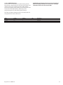
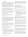
5.6.2 - Reset
Reset means that the active setpoint is modifi ed so that less
machine capacity is required (in cooling mode, the setpoint is
increased, in heating mode it is decreased). This modifi ca-tion
is in general a reaction to a drop in the load. For the Pro-
Dialog control system, the source of the reset can be
confi gured in the HCCONFIG confi guration: it can be
provided either by the outdoor temperature (that gives a
measure of the load trends for the building) or by the return
water temperature (heat exchanger delta T, gives an average
building load).
In response to a drop in the outdoor temperature or to a
drop in delta T, the cooling setpoint is normally reset
upwards in order to optimise unit performance:
In both cases the reset parameters, i.e. slope, source and
maximum value, are confi gurable in the RESETCFG menu (see
section 4.3.8). Reset is a linear function based on three
parameters.
• A reference at which reset is zero (outdoor temperature or
delta T - no reset value).
• A reference at which reset is maximum (outdoor
temperature or delta T - full reset value).
• The maximum reset value.
Reset example in cooling mode based on the outside
temperature
Legend
A Maximum reset value
B OAT or delta T for no reset
C OAT or delta T for full reset
D Building Load
5.7 - Demand limit
The demand limit is used to restrict the unit power
consumption. The Pro-Dialog control system allows limitation
of the unit capacity, using user-controlled volt-free contacts.
The unit capacity can never exceed the limit setpoint
activated by these contacts. The limit setpoints can be
modifi ed in the SETPOINT menu.
5.8 - Night mode
The night period is defi ned (see GENUNIT confi guration) by a
start time and an end time that are the same for each day of
the week. During the night period, the number of fans
operating can be reduced, and the unit capacity may be
limited.
Reset value
Outdoor temperature (OAT)
Heat exchanger delta T
% Building load
Page is loading ...
Page is loading ...
Page is loading ...
Page is loading ...
Page is loading ...
-
 1
1
-
 2
2
-
 3
3
-
 4
4
-
 5
5
-
 6
6
-
 7
7
-
 8
8
-
 9
9
-
 10
10
-
 11
11
-
 12
12
-
 13
13
-
 14
14
-
 15
15
-
 16
16
-
 17
17
-
 18
18
-
 19
19
-
 20
20
-
 21
21
-
 22
22
-
 23
23
-
 24
24
-
 25
25


Ask a question and I''ll find the answer in the document
Finding information in a document is now easier with AI
Related papers
Other documents
-
 Adax NEO S5.1 User manual
-
 Master-Bilt Master Controller-Legacy 1.0 Systems User manual
-
klima SF300 User manual
-
Grasslin MIL 72 A-E 1 digi 42 Owner's manual
-
Conceptronic 1300053 Datasheet
-
Carrier Refrigerator 30XW150-400 User manual
-
 Paladin 1794X0 - SC88 Owner's manual
-
Carrier AQUASNAP 30RY/RYH Operation & Maintenance Instructions Manual
-
-
 Master-Bilt Master Controller User manual


