Page is loading ...

Manufacturer reserves the right to discontinue, or change at any time, specifications or designs without notice and without incurring obligations.
Catalog No. 04-53300067-01 Printed in U.S.A. Form 30RAP-2T Pg 1 12-10 Replaces: 30RAP-1T
Controls, Start-Up, Operation,
Service, and Troubleshooting
CONTENTS
Page
SAFETY CONSIDERATIONS . . . . . . . . . . . . . . . . . . . . . . . . .2
GENERAL . . . . . . . . . . . . . . . . . . . . . . . . . . . . . . . . . . . . . . . . 3-18
Conventions Used in this Manual. . . . . . . . . . . . . . . . . . . .3
Basic Controls Usage . . . . . . . . . . . . . . . . . . . . . . . . . . . . . . .3
CONTROLS. . . . . . . . . . . . . . . . . . . . . . . . . . . . . . . . . . . . . . 19-44
General. . . . . . . . . . . . . . . . . . . . . . . . . . . . . . . . . . . . . . . . . . . . .19
Main Base Board (MBB) . . . . . . . . . . . . . . . . . . . . . . . . . . . .19
Energy Management Module (EMM) . . . . . . . . . . . . . . . .19
Current Sensor Board (CSB) . . . . . . . . . . . . . . . . . . . . . . .19
AUX Board (AUX) . . . . . . . . . . . . . . . . . . . . . . . . . . . . . . . . . . .19
Expansion Valve Board (EXV) . . . . . . . . . . . . . . . . . . . . . .19
Enable/Off/Remote Contact Switch . . . . . . . . . . . . . . . . .19
Emergency On/Off Switch . . . . . . . . . . . . . . . . . . . . . . . . . .19
Board Addresses . . . . . . . . . . . . . . . . . . . . . . . . . . . . . . . . . . .19
Control Module Communication . . . . . . . . . . . . . . . . . . . .19
Carrier Comfort Network
®
(CCN) Interface . . . . . . . . . .19
Sensors . . . . . . . . . . . . . . . . . . . . . . . . . . . . . . . . . . . . . . . . . . . .20
• COOLER LEAVING FLUID SENSOR
• COOLER ENTERING FLUID SENSOR
• COMPRESSOR RETURN GAS
TEMPERATURE SENSOR
• OUTDOOR-AIR TEMPERATURE SENSOR (OAT)
• DISCHARGE TEMPERATURE THERMISTOR (DTT)
• REMOTE SPACE TEMPERATURE SENSOR OR DUAL
LEAVING WATER TEMPERATURE SENSOR
Energy Management Module . . . . . . . . . . . . . . . . . . . . . . .29
Loss-of-Cooler Flow Protection. . . . . . . . . . . . . . . . . . . . .29
Electronic Expansion Valves (EXV) . . . . . . . . . . . . . . . . .29
Capacity Control . . . . . . . . . . . . . . . . . . . . . . . . . . . . . . . . . . .29
• MINUTES LEFT FOR START
• MINUTES OFF TIME
• LEAD/LAG DETERMINATION
• CAPACITY CONTROL OVERRIDES
Head Pressure Control . . . . . . . . . . . . . . . . . . . . . . . . . . . . .32
Operation of Machine Based on Control Method
and Cooling Set Point Selection Settings. . . . . . . . .32
Cooling Set Point Select. . . . . . . . . . . . . . . . . . . . . . . . . . . .33
Low Sound Mode Operation . . . . . . . . . . . . . . . . . . . . . . . .34
Heating Operation . . . . . . . . . . . . . . . . . . . . . . . . . . . . . . . . . .34
Service Test . . . . . . . . . . . . . . . . . . . . . . . . . . . . . . . . . . . . . . . .34
Optional Factory-Installed Hydronic Package. . . . . . .34
Cooler Pump Control . . . . . . . . . . . . . . . . . . . . . . . . . . . . . . .34
Cooler Pump Sequence of Operation . . . . . . . . . . . . . . .35
Configuring and Operating Dual Chiller Control . . . .36
Temperature Reset . . . . . . . . . . . . . . . . . . . . . . . . . . . . . . . . .38
Demand Limit . . . . . . . . . . . . . . . . . . . . . . . . . . . . . . . . . . . . . .42
• DEMAND LIMIT (2-Stage Switch Controlled)
• EXTERNALLY POWERED DEMAND LIMIT
(4 to 20 mA Controlled)
• DEMAND LIMIT (CCN Loadshed Controlled)
Cooling Set Point (4 to 20 mA). . . . . . . . . . . . . . . . . . . . . .43
Digital Scroll Option . . . . . . . . . . . . . . . . . . . . . . . . . . . . . . . .44
• DIGITAL SCROLL OPERATION
• DIGITAL COMPRESSOR CONFIGURATION
PRE-START-UP . . . . . . . . . . . . . . . . . . . . . . . . . . . . . . . . . . 44,45
Page
System Check. . . . . . . . . . . . . . . . . . . . . . . . . . . . . . . . . . . . . . 44
START-UP AND OPERATION . . . . . . . . . . . . . . . . . . . . 45,46
Actual Start-Up. . . . . . . . . . . . . . . . . . . . . . . . . . . . . . . . . . . . . 45
Check Refrigerant Charge . . . . . . . . . . . . . . . . . . . . . . . . . 45
Operating Limitations . . . . . . . . . . . . . . . . . . . . . . . . . . . . . . 46
• TEMPERATURES
• LOW AMBIENT OPERATION
• VOLTAGE — ALL UNITS
OPERATION SEQUENCE . . . . . . . . . . . . . . . . . . . . . .46,47
SERVICE . . . . . . . . . . . . . . . . . . . . . . . . . . . . . . . . . . . . . 47-63
Electronic Components . . . . . . . . . . . . . . . . . . . . . . . . . . . . 47
• CONTROL COMPONENTS
Electronic Expansion Valve (EXV) . . . . . . . . . . . . . . . 47
EXV Troubleshooting Procedure . . . . . . . . . . . . . . . . . . . 47
• FIELD SERVICING INSTRUCTIONS
• VALVE REPLACEMENT
• VALVE REASSEMBLY
Compressor Replacement. . . . . . . . . . . . . . . . . . . . . . . . . . 49
Cooler. . . . . . . . . . . . . . . . . . . . . . . . . . . . . . . . . . . . . . . . . . . . . . 49
• BRAZED-PLATE COOLER HEAT EXCHANGER
REPLACEMENT
• BRAZED-PLATE COOLER HEAT EXCHANGER
CLEANING
Oil Charge. . . . . . . . . . . . . . . . . . . . . . . . . . . . . . . . . . . . . . . . . . 50
Microchannel Heat Exchanger (MCHX)
Condenser Coil Maintenance and Cleaning
Recommendations . . . . . . . . . . . . . . . . . . . . . . . . . . . . . . 50
Check Refrigerant Feed Components . . . . . . . . . . . . . . 50
•FILTER DRIER
• MOISTURE-LIQUID INDICATOR
• MINIMUM LOAD VALVE
• PRESSURE RELIEF DEVICES
Check Unit Safeties . . . . . . . . . . . . . . . . . . . . . . . . . . . . . . . . 52
• HIGH-PRESSURE SWITCH
• PRESSURE TRANSDUCERS
• COOLER FREEZE-UP PROTECTION
• HEATER CABLE
• WINTER SHUTDOWN
Thermistors . . . . . . . . . . . . . . . . . . . . . . . . . . . . . . . . . . . . . . . . 52
Pressure Transducers . . . . . . . . . . . . . . . . . . . . . . . . . . . . . . 53
Chilled Water Flow Switch. . . . . . . . . . . . . . . . . . . . . . . . . . 53
Strainer . . . . . . . . . . . . . . . . . . . . . . . . . . . . . . . . . . . . . . . . . . . . 53
Condenser Fans. . . . . . . . . . . . . . . . . . . . . . . . . . . . . . . . . . . . 53
Motormaster
®
V Controller . . . . . . . . . . . . . . . . . . . . . . . . . 58
• GENERAL OPERATION
• CONFIGURATION
• DRIVE PROGRAMMING
•EPM CHIP
• LOSS OF CCN COMMUNICATIONS
• REPLACING DEFECTIVE MODULES
Hydronic Package . . . . . . . . . . . . . . . . . . . . . . . . . . . . . . . . . . 63
MAINTENANCE. . . . . . . . . . . . . . . . . . . . . . . . . . . . . . . . . . 63,64
Recommended Maintenance Schedule . . . . . . . . . . . . . 63
Microchannel Heat Exchanger (MCHX)
Condenser Coil Maintenance and Cleaning
Recommendations . . . . . . . . . . . . . . . . . . . . . . . . . . . . . . 64
TROUBLESHOOTING. . . . . . . . . . . . . . . . . . . . . . . . . . . . 64-73
30RAP010-060
AQUASNAP
®
Air-Cooled Chillers
with COMFORTLINK™ Controls

2
CONTENTS (cont)
Page
Complete Unit Stoppage and Restart . . . . . . . . . . . . . . 64
• GENERAL POWER FAILURE
• UNIT ENABLE-OFF-REMOTE CONTACT SWITCH IS
OFF
• CHILLED FLUID PROOF-OF-FLOW SWITCH OPEN
• OPEN 24-V CONTROL CIRCUIT BREAKERS
• COOLING LOAD SATISFIED
• THERMISTOR FAILURE
• LOW SATURATED SUCTION
• COMPRESSOR SAFETIES
Alarms and Alerts. . . . . . . . . . . . . . . . . . . . . . . . . . . . . . . . . . 65
APPENDIX A — DISPLAY TABLES . . . . . . . . . . . . . . 74-89
APPENDIX B — CCN TABLES . . . . . . . . . . . . . . . . . . 90-100
APPENDIX C — FACTORY SETTINGS FOR
PUMP AND MANUAL STARTERS. . . . . . . . . . . . . . . . 101
APPENDIX D — OPTIONAL BACNET
COMMUNICATONS WIRING . . . . . . . . . . . . . . . . . 102-109
APPENDIX E — MAINTENANCE SUMMARY
AND LOG SHEETS . . . . . . . . . . . . . . . . . . . . . . . . . . 110-113
START-UP CHECKLIST FOR 30RAP LIQUID
CHILLER
. . . . . . . . . . . . . . . . . . . . . . . . . . . . . CL-1 to CL-10
SAFETY CONSIDERATIONS
Installing, starting up, and servicing this equipment can be
hazardous due to system pressures, electrical components, and
equipment location (roof, elevated structures, mechanical
rooms, etc.). Only trained, qualified installers and service
mechanics should install, start up, and service this equipment.
When working on this equipment, observe precautions in
the literature, and on tags, stickers, and labels attached to the
equipment, and any other safety precautions that apply. Follow
all safety codes. Wear safety glasses and work gloves. Use
care in handling, rigging, and setting this equipment, and in
handling all electrical components.
WARNING
Electrical shock can cause personal injury and death. Shut
off all power to this equipment during installation. There
may be more than one disconnect switch. Tag all discon-
nect locations to alert others not to restore power until work
is completed.
WARNING
DO NOT VENT refrigerant relief valves within a building.
Outlet from relief valves must be vented outdoors in
accordance with the latest edition of ANSI/ASHRAE
(American National Standards Institute/American Society
of Heating, Refrigeration and Air Conditioning Engineers)
15 (Safety Code for Mechanical Refrigeration). The
accumulation of refrigerant in an enclosed space can
displace oxygen and cause asphyxiation. Provide adequate
ventilation in enclosed or low overhead areas. Inhalation of
high concentrations of vapor is harmful and may cause
heart irregularities, unconsciousness or death. Misuse can
be fatal. Vapor is heavier than air and reduces the amount
of oxygen available for breathing. Product causes eye and
skin irritation. Decomposition products are hazardous.
WARNING
DO NOT attempt to unbraze factory joints when servicing
this equipment. Compressor oil is flammable and there is
no way to detect how much oil may be in any of the
refrigerant lines. Cut lines with a tubing cutter as required
when performing service. Use a pan to catch any oil that
may come out of the lines and as a gage for how much oil
to add to system. DO NOT re-use compressor oil.
CAUTION
This unit uses a microprocessor-based electronic control
system. Do not use jumpers or other tools to short out
components, or to bypass or otherwise depart from recom-
mended procedures. Any short-to-ground of the control
board or accompanying wiring may destroy the electronic
modules or electrical components.
CAUTION
To prevent potential damage to heat exchanger, always run
fluid through heat exchanger when adding or removing
refrigerant charge. Use appropriate brine solutions in cooler
fluid loop to prevent the freezing of brazed plate heat
exchanger, optional hydronic section and/or interconnecting
piping when the equipment is exposed to temperatures
below 32 F (0 °C). Proof of flow switch and strainer are
factory installed on all models. Do NOT remove power
from this chiller during winter shutdown periods without
taking precaution to remove all water from heat exchanger
and optional hydronic system. Failure to properly protect
the system from freezing may constitute abuse and may
void warranty.
CAUTION
Compressors and optional hydronic system pumps require
specific rotation. Test condenser fan(s) first to ensure
proper phasing. Swap any two incoming power leads to
correct condenser fan rotation before starting any other
motors.
CAUTION
Refrigerant charge must be removed slowly to prevent loss
of compressor oil that could result in compressor failure.
CAUTION
Puron
®
refrigerant (R-410A) systems operate at higher
pressures than standard R-22 systems. Do not use R-22 ser-
vice equipment or components on Puron refrigerant equip-
ment. If service equipment is not rated for Puron
refrigerant, equipment damage or personal injury may
result.

3
GENERAL
This publication contains Controls, Start-Up, Operation,
Service, and Troubleshooting information for the 30RAP
AquaSnap
®
air-cooled chillers. See Table 1. These chillers are
equipped with ComfortLink™ controls and electronic expan-
sion valves (EXVs).
Table 1 — Unit Sizes
Conventions Used in This Manual — The follow-
ing conventions for discussing configuration points for the
local display (scrolling marquee or Navigator™ accessory)
will be used in this manual.
Point names will be written with the mode name first, then
any sub-modes, then the point name, each separated by an
arrow symbol (. Names will also be shown in bold
and italics. As an example, the Lead/Lag Circuit Select Point,
which is located in the Configuration mode, Option sub-mode,
would be written as Configuration OPTNLLCS.
This path name will show the user how to navigate through
the local display to reach the desired configuration. The user
would scroll through the modes and sub-modes using the
and keys. The arrow symbol in the path name repre-
sents pressing to move into the next level of the
menu structure.
When a value is included as part of the path name, it will be
shown at the end of the path name after an equals sign. If the
value represents a configuration setting, an explanation will
be shown in parenthesis after the value. As an example,
ConfigurationOPTNLLCS = 1 (Circuit A leads).
Pressing the and keys simultaneously
will scroll an expanded text description of the point name or
value across the display. The expanded description is shown in
the local display tables but will not be shown with the path
names in text.
The CCN (Carrier Comfort Network
®
) point names are also
referenced in the local display tables for users configuring the
unit with CCN software instead of the local display. The CCN
tables are located in Appendix B of the manual.
Basic Controls Usage
SCROLLING MARQUEE DISPLAY — The scrolling mar-
quee display is the standard interface display to the ComfortLink
Control System for 30RAP units. The display has up and down
arrow keys, an key, and an key. These
keys are used to navigate through the different levels of the
display structure. Press the key until the highest
operating level is displayed to move through the top 11 mode
levels indicated by LEDs on the left side of the display. See
Fig. 1 and Tables 2-14.
Once within a mode or sub-mode, pressing the
and keys simultaneously will put the scrolling
marquee display into expanded text mode where the full mean-
ing of all sub-modes, items and their values can be displayed
for the current selection. Press the and
keys to return the scrolling marquee display to its default menu
of rotating display items (those items in Run Status
VIEW).
In addition, the password will be disabled, requiring that it be
entered again before changes can be made to password protect-
ed items. Press the key to exit out of the expanded
text mode.
NOTE: When the Language Selection (Configuration
DISP
LANG), variable is changed, all appropriate display
expansions will immediately change to the new language. No
power-off or control reset is required when reconfiguring
languages.
When a specific item is located, the item name alternates
with the value. Press the key at a changeable item
and the value will be displayed. Press again and the
value will begin to flash indicating that the value can be
changed. Use the up and down arrow keys to change the value,
and confirm the value by pressing the key.
Changing item values or testing outputs is accomplished in
the same manner. Locate and display the desired item. Press
so that the item value flashes. Use the arrow keys to
change the value or state and press the key to accept
it. Press the key to return to the next higher level of
structure. Repeat the process as required for other items.
Items in the Configuration and Service Test modes are pass-
word protected. The words ‘PASS’ and ‘WORD’ will alternate
on the display when required. The default password is 0111.
Press and the 1111 password will be displayed. Press
again and the first digit will begin to flash. Use the
arrow keys to change the number and press to accept
the digit. Continue with the remaining digits of the password.
The password can only be changed through CCN operator in-
terface software such as ComfortWORKS
®
, ComfortVIEW™
and Service Tool.
See Tables 2-14 and Appendix A for further details.
WARNING
This unit uses a microprocessor-based electronic control
system. Do not use jumpers or other tools to short out or
bypass components or otherwise depart from recom-
mended procedures. Any short-to-ground of the control
board or accompanying wiring may destroy the board or
electrical component.
UNIT NOMINAL CAPACITY (TONS)
30RAP010 10
30RAP015 14
30RAP018 16
30RAP020 19
30RAP025 24
30RAP030 28
30RAP035 34
30RAP040 39
30RAP045 43
30RAP050 48
30RAP055 53
30RAP060 56
ENTER
ESCAPE
ENTER
ENTER
ESCAPE
ESCAPE
ENTER
ESCAPE
ENTER
ESCAPE
ESCAPE
ENTER
ENTER
ENTER
Run Status
Service Test
Temperature
Pressures
Setpoints
Inputs
Outputs
Configuration
Time Clock
Operating Modes
Alarms
Alarm Status
ENTER
MODE
ESCAPE
Fig. 1 — Scrolling Marquee Display
ENTER
ENTER
ESCAPE
ENTER
ENTER
ENTER

4
ACCESSORY NAVIGATOR™ DISPLAY MODULE —
The Navigator module provides a mobile user interface to the
ComfortLink™ control system, which is only available as a
field-installed accessory. The display has up and down arrow
keys, an key, and an key. These keys are
used to navigate through the different levels of the display
structure. Press the key until ‘Select a Menu Item’
is displayed to move through the top 11 mode levels indicated
by LEDs on the left side of the display. See Fig. 2.
Once within a Mode or sub-mode, a “>” indicates the cur-
rently selected item on the display screen. Pressing the
and keys simultaneously will put the Nav-
igator module into expanded text mode where the full meaning
of all sub-modes, items and their values can be displayed. Press-
ing the and keys when the display says
‘Select Menu Item’ (Mode LED level) will return the Navigator
module to its default menu of rotating display items (those items
in Run Status
VIEW). In addition, the password will be dis-
abled, requiring that it be entered again before changes can be
made to password protected items. Press the key to
exit out of the expanded text mode.
NOTE: When the Language Selection (Configuration
DISP
LANG), variable is changed, all appropriate display
expansions will immediately change to the new language. No
power-off or control reset is required when reconfiguring
languages.
When a specific item is located, the item name appears on the
left of the display, the value will appear near the middle of the
display and the units (if any) will appear on the far right of the
display. Press the key at a changeable item and the val-
ue will begin to flash. Use the up and down arrow keys to change
the value, and confirm the value by pressing the key.
Changing item values or testing outputs is accomplished in
the same manner. Locate and display the desired item. Press
so that the item value flashes. Use the arrow keys to
change the value or state and press the key to accept
it. Press the key to return to the next higher level of
structure. Repeat the process as required for other items.
Items in the Configuration and Service Test modes are pass-
word protected. The words Enter Password will be displayed
when required, with 1111 also being displayed. The default
password is 1111. Use the arrow keys to change the number
and press to enter the digit. Continue with the re-
maining digits of the password. The password can only be
changed through CCN operator interface software such as
ComfortWORKS, ComfortVIEW and Service Tool.
Adjusting the Contrast
— The contrast of the display can be
adjusted to suit ambient conditions. To adjust the contrast of
the Navigator module, press the key until the dis-
play reads, “Select a menu item.” Using the arrow keys move
to the Configuration mode. Press to obtain access to
this mode. The display will read:
> TEST OFF
METR OFF
LANG ENGLISH
Pressing will cause the “OFF” to flash. Use the up
or down arrow to change “OFF” to “ON”. Pressing
will illuminate all LEDs and display all pixels in the view
screen. Pressing and simultaneously
allows the user to adjust the display contrast. Use the up or
down arrows to adjust the contrast. The screen’s contrast will
change with the adjustment. Press to accept the
change. The Navigator module will keep this setting as long as
it is plugged in to the LEN bus.
Adjusting the Backlight Brightness
— The backlight of the
display can be adjusted to suit ambient conditions. The factory
default is set to the highest level. To adjust the backlight of the
Navigator module, press the key until the display
reads, “Select a menu item.” Using the arrow keys move to the
Configuration mode. Press to obtain access to this
mode. The display will read:
> TEST OFF
METR OFF
LANG ENGLISH
Pressing will cause the “OFF” to flash. Use the up
or down arrow keys to change “OFF” to “ON”. Pressing
will illuminate all LEDs and display all pixels in the
view screen. Pressing the up and down arrow keys simultane-
ously allows the user to adjust the display brightness. Use the
up or down arrow keys to adjust screen brightness. Press
to accept the change. The Navigator module will
keep this setting as long as it is plugged in to the LEN bus.
ENTER
ESCAPE
ESCAPE
ENTER
ESCAPE
ENTER
ESCAPE
ESCAPE
ENTER
ENTER
ENTER
ENTER
ESCAPE
ENTER
ESCAPE
ENTER
ENTER
ENTER
ENTER
ESCAPE
ENTER
ESCAPE
ENTER
ENTER
ENTER
ENTER
Run Status
Service Tes t
Tem peratures
Pressure
s
Setpoints
Inputs
Outputs
Configuration
Time Clock
Operating Modes
Alarms
ENTER
ESC
MODE
Alarm Status
ComfortLink
Fig. 2 — Accessory Navigator™ Display Module

5
Table 2 — Scrolling Marquee Display Menu Structure*
LEGEND
Ckt — Circuit
*Throughout this text, the location of items in the menu structure will be
described in the following format:
Item Expansion (Mode Name
Sub-mode Name
ITEM)
For example, using the language selection item:
Language Selection (Configuration
DISP
LANG)
MODE
RUN
STATUS
SERVICE
TEST
TEMPERATURES PRESSURES
SET
POINTS
INPUTS OUTPUTS CONFIGURATION
TIME
CLOCK
OPERATING
MODES
ALARMS
SUB-MODE
Auto
View of
Run Status
(VIEW)
Service
Te st M o de
(TEST)
Ent and Leave Unit
Te mp s
(UNIT)
Pressures
Ckt A
(PRC.A)
Cooling
Setpoints
(COOL)
General
Inputs
(GEN.I)
General
Outputs
(GEN.O)
Display
Configuration
(DISP)
Time of
Day
(TIME)
Modes
(MODE)
Current
(CRNT)
Unit Run
Hour and
Start
(RUN)
Outputs
and Pumps
(OUTS)
Temperatures
Ckt A
(CIR.A)
Pressures
Ckt B
(PRC.B)
Head
Pressure
Setpoint
(HEAD)
Circuit
Inputs
(CRCT)
Outputs
Circuit A
EXV
(A.EXV)
Unit
Configuration
(UNIT)
Month,
Date, Day,
and Year
(DATE)
Reset
Alarms
(RCRN)
Compressor
Run Hours
(HOUR)
Ciruit A Comp
Te st
(CMPA)
Temperatures
Ckt B
(CIR.B)
Brine
Freeze
Setpoint
(FRZ)
4-20mA
Inputs
(4-20)
Outputs
Circuit B
EXV
(B.EXV)
Unit Options 1
Hardware
(OPT1)
Daylight
Savings
Time
(DST)
Alarm
History
(HIST)
Local
Holiday
Schedules
(HOL.L)
Compressor
Starts
(STRT)
Ciruit B Comp
Test
(CMPB)
Outputs
Circuit A
(CIR.A)
Unit Options 2
Controls
(OPT2)
Preventive
Maintenance
(PM)
Outputs
Circuit B
(CIR.B)
CCN Network
Configuration
(CCN)
Local
Occu-
pancy
Schedule
(SCH.L)
Software
Version
(VERS)
Head Pressure
Comp. Delta
(HP.A)
Schedule
Override
(OVR)
Head Pressure
Comp. Delta
(HP.B)
Cir. A EXV
Configuration
(EXV.A)
Cir. B EXV
Configuration
(EXV.B)
Motormaster
Configuration
(MM)
Reset Cool Temp
(RSET)
Set Point and
Ramp Load
(SLCT)
Service
Configuration
(SERV)
Broadcast
Configuration
(BCST)

6
Table 3 — Run Status Mode and Sub-Mode Directory
NOTE: If the unit has a single circuit, the Circuit B items will not appear in the display, except the ability to configure circuit B will be displayed.
SUB-MODE
KEYPAD
ENTRY
ITEM DISPLAY SUB-ITEM DISPLAY SUB-ITEM DISPLAY
ITEM
EXPANSION
COMMENT
VIEW EWT XXX.X F ENTERING FLUID TEMP
LWT XXX.X F LEAVING FLUID TEMP
SETP XXX.X F ACTIVE SETPOINT
CTPT XXX.X F CONTROL POINT
LOD.F XXX LOAD/UNLOAD FACTOR
STAT X CONTROL MODE 0 = Service Test
1 = Off Local
2 = Off CCN
3 = Off Time
4 = Off Emrgcy
5 = On Local
6 = On CCN
7 = On Time
8 = Ht Enabled
9 = Pump Delay
LD.PM LEAD PUMP
OCC YES/NO OCCUPIED
LS.AC YES/NO LOW SOUND ACTIVE
MODE YES/NO OVERRIDE MODES IN EFFECT
CAP XXX % PERCENT TOTAL CAPACITY
STGE X REQUESTED STAGE
ALRM XXX CURRENT ALARMS & ALERTS
TIME XX.XX TIME OF DAY 00.00-23.59
MNTH XX MONTH OF YEAR 1 = January, 2 = February, etc.
DATE XX DAY OF MONTH 01-31
YEAR XX YEAR OF CENTURY
RUN HRS.U XXXX HRS MACHINE OPERATING HOURS
STR.U XXXX MACHINE STARTS
HR.P1 XXXX.X PUMP 1 RUN HOURS
HR.P2 XXXX.X PUMP 2 RUN HOURS
HOUR HRS.A XXXX HRS CIRCUIT A RUN HOURS
HRS.B XXXX HRS CIRCUIT B RUN HOURS See Note
HR.A1 XXXX HRS COMPRESSOR A1 RUN HOURS
HR.A2 XXXX HRS COMPRESSOR A2 RUN HOURS
HR.B1 XXXX HRS COMPRESSOR B1 RUN HOURS See Note
HR.B2 XXXX HRS COMPRESSOR B2 RUN HOURS See Note
STRT ST.A1 XXXX COMPRESSOR A1 STARTS
ST.A2 XXXX COMPRESSOR A2 STARTS
ST.B1 XXXX COMPRESSOR B1 STARTS See Note
ST.B2 XXXX COMPRESSOR B2 STARTS See Note
PM PUMP PUMP MAINTENANCE
SI.PM XXXX HRS PUMP SERVICE INTERVAL Default: 8760
P.1.DN XXXX HRS PUMP 1 SERVICE COUNTDOWN
P.2.DN XXXX HRS PUMP 2 SERVICE COUNTDOWN
P.1.MN YES/NO PUMP 1 MAINTENANCE DONE User Entry
P.2.MN YES/NO PUMP 2 MAINTENANCE DONE User Entry
ENTER
ENTER
ENTER
ENTER
ENTER
ENTER

7
Table 3 — Run Status Mode and Sub-Mode Directory (cont)
*Press and simultaneously to obtain version number.
SUB-MODE
KEYPAD
ENTRY
ITEM DISPLAY SUB-ITEM DISPLAY SUB-ITEM DISPLAY
ITEM
EXPANSION
COMMENT
PM (cont) PMDT PUMP MAINTENANCE DATES
P.1.M0 MM/DD/YY HH:MM
P.1.M1 MM/DD/YY HH:MM
P.1.M2 MM/DD/YY HH:MM
P.1.M3 MM/DD/YY HH:MM
P.1.M4 MM/DD/YY HH:MM
P.2.M0 MM/DD/YY HH:MM
P.2.M1 MM/DD/YY HH:MM
P.2.M2 MM/DD/YY HH:MM
P.2.M3 MM/DD/YY HH:MM
P.2.M4 MM/DD/YY HH:MM
STRN STRAINER MAINTENANCE
SI.ST XXXX HRS STRAINER SRVC INTERVAL Default: 8760
S.T.DN XXXX HRS STRAINER SRVC COUNTDOWN
S.T.MN YES/NO STRAINER MAINT. DONE User Entry
ST.DT STRAINER MAINT. DATES
S.T.M0 MM/DD/YY HH:MM
S.T.M1 MM/DD/YY HH:MM
S.T.M2 MM/DD/YY HH:MM
S.T.M3 MM/DD/YY HH:MM
S.T.M4 MM/DD/YY HH:MM
COIL COIL MAINTENANCE
SI.CL XXXX HRS COIL SRVC INTER Default: 8760
C.L.DN XXXX HRS COIL SERVICE COUNTDOWN
C.L.MN YES/NO COIL MAINT. DONE User Entry
CL.DT COIL MAINTENANCE DATES
C.L.M0 MM/DD/YY HH:MM
C.L.M1 MM/DD/YY HH:MM
C.L.M2 MM/DD/YY HH:MM
C.L.M3 MM/DD/YY HH:MM
C.L.M4 MM/DD/YY HH:MM
VERS MBB CESR131460-xx-xx xx-xx is Version number*
EXV CESR131172-xx-xx xx-xx is Version number*
AUX1 CESR131333-xx-xx xx-xx is Version number*
EMM CESR131174-xx-xx xx-xx is Version number*
MARQ CESR131171-xx-xx xx-xx is Version number*
NAVI CESR130227-xx-xx xx-xx is Version number*
ENTER
ENTER
ENTER
ENTER
ENTER
ENTER
ENTER
ENTER
ENTER
ESCAPE

8
Table 4 — Service Test Mode and Sub-Mode Directory
NOTE: If the unit has a single circuit, the Circuit B items will not appear in the display, except the ability to configure circuit B will be displayed.
SUB-MODE
KEYPAD
ENTRY
ITEM DISPLAY
ITEM
EXPANSION
COMMENT
TEST ON/OFF SERVICE TEST MODE To Enable Service Test Mode,
move Enable/Off/Remote
Contact switch to OFF. Change
TEST to ON. Move switch to
ENABLE.
OUTS OUTPUTS AND PUMPS
EXV.A 0 to 100% EXV A % OPEN
EXV.B 0 to 100% EXV B % OPEN
FAN1 ON/OFF FAN 1 RELAY
FAN2 ON/OFF FAN 2 RELAY
FAN3 ON/OFF FAN 3 RELAY
FAN4 ON/OFF FAN 4 RELAY
FAN5 ON/OFF FAN 5 RELAY
FAN6 ON/OFF FAN 6 RELAY
V.HPA 0 to 100% VAR HEAD PRESS %
V.HPB 0 to 100% VAR HEAD PRESS %
CLP.1 ON/OFF COOLER PUMP 1 RELAY
CLP.2 ON/OFF COOLER PUMP 2 RELAY
UL.TM 0 to 15 COMP A1 UNLOAD TIME
CL.HT ON/OFF COOLER/PUMP HEATER
RMT.A ON/OFF REMOTE ALARM RELAY
CMPA CIRCUIT A COMPRESSOR TEST
CC.A1 ON/OFF COMPRESSOR A1 RELAY
UL.TM 0 to 15 COMP A1 UNLOAD TIME
CC.A2 ON/OFF COMPRESSOR A2 RELAY
CC.A3 ON/OFF COMPRESSOR A3 RELAY
CC.A4 ON/OFF COMPRESSOR A4 RELAY
MLV ON/OFF MINIMUM LOAD VALVE RELAY
CMPB CIRCUIT B COMPRESSOR TEST See Note
CC.B1 ON/OFF COMPRESSOR B1 RELAY
CC.B2 ON/OFF COMPRESSOR B2 RELAY
CC.B3 ON/OFF COMPRESSOR B3 RELAY
CC.B4 ON/OFF COMPRESSOR B4 RELAY
ENTER
ENTER
ENTER
ENTER

9
Table 5 — Temperature Mode and Sub-Mode Directory
NOTE: If the unit has a single circuit, the Circuit B items will not appear in the display, except the ability to configure circuit B will be displayed.
Table 6 — Pressure Mode and Sub-Mode Directory
NOTE: If the unit has a single circuit, the Circuit B items will not appear in the display, except the ability to configure circuit B will be displayed.
Table 7 — Set Points Mode and Sub-Mode Directory
SUB-MODE
KEYPAD
ENTRY
ITEM DISPLAY
ITEM
EXPANSION
COMMENT
UNIT ENT AND LEAVE UNIT TEMPS
CEWT XXX.X F COOLER ENTERING FLUID
CLWT XXX.X F COOLER LEAVING FLUID
OAT XXX.X F OUTSIDE AIR TEMPERATURE
SPT XXX.X F SPACE TEMPERATURE
DLWT XXX.X F LEAD/LAG LEAVING FLUID
CIR.A TEMPERATURES CIRCUIT A
SCT.A XXX.X F SATURATED CONDENSING TMP
SST.A XXX.X F SATURATED SUCTION TEMP
RGT.A XXX.X F COMPR RETURN GAS TEMP
D.GAS XXX.X F DISCHARGE GAS TEMP
SH.A XXX.X ^F SUCTION SUPERHEAT TEMP
CIR.B TEMPERATURES CIRCUIT B See Note
SCT.B XXX.X F SATURATED CONDENSING TMP See Note
SST.B XXX.X F SATURATED SUCTION TEMP See Note
RGT.B XXX.X F COMPR RETURN GAS TEMP See Note
SH.B XXX.X ^F SUCTION SUPERHEAT TEMP See Note
SUB-MODE
KEYPAD
ENTRY
ITEM DISPLAY
ITEM
EXPANSION
COMMENT
PRC.A PRESSURES CIRCUIT A
DP.A XXX.X PSIG DISCHARGE PRESSURE
SP.A XXX.X PSIG SUCTION PRESSURE
PRC.B PRESSURES CIRCUIT B See Note
DP.B XXX.X PSIG DISCHARGE PRESSURE See Note
SP.B XXX.X PSIG SUCTION PRESSURE See Note
SUB-MODE
KEYPAD
ENTRY
ITEM DISPLAY
ITEM
EXPANSION
COMMENT
COOL COOLING SETPOINTS
CSP.1 XXX.X
F COOLING SETPOINT 1 Default: 44 F
CSP.2 XXX.X F COOLING SETPOINT 2 Default: 44 F
CSP.3 XXX.X F ICE SETPOINT Default: 32 F
HEAD HEAD PRESSURE SETPOINTS
H.DP XXX.X F HEAD SETPOINT Default: 95 F
F. O N XXX.X F FAN ON SETPOINT Default: 95 F
F. O F F XXX.X F FAN OFF SETPOINT Default: 72 F
B.OFF XXX.X F BASE FAN OFF DELTA TEMP Default: 23 F
F. D LT XXX.X F FAN STAGE DELTA Default: 15 F
FRZ BRINE FREEZE SETPOINT
BR.FZ XXX.X F BRINE FREEZE POINT Default: 34 F
ENTER
ENTER
ENTER
ENTER
ENTER
ENTER
ENTER
ENTER

10
Table 8 — Inputs Mode and Sub-Mode Directory
NOTE: If the unit has a single circuit, the Circuit B items will not appear in the display, except the ability to configure circuit B will be displayed.
Table 9 — Outputs Mode and Sub-Mode Directory
SUB-MODE
KEYPAD
ENTRY
ITEM DISPLAY
ITEM
EXPANSION
COMMENT
GEN.I GENERAL INPUTS
STST STRT/STOP START/STOP SWITCH
FLOW ON/OFF COOLER FLOW SWITCH
PM.F.1 OPEN/CLSE COOLER PUMP 1 INTERLOCK
PM.F.2 OPEN/CLSE COOLER PUMP 2 INTERLOCK
HT.RQ ON/OFF HEAT REQUEST
DLS1 ON/OFF DEMAND LIMIT SWITCH 1
DLS2 ON/OFF DEMAND LIMIT SWITCH 2
ICED ON/OFF ICE DONE
DUAL ON/OFF DUAL SETPOINT SWITCH
CRCT CIRCUITS INPUTS
FKA1 ON/OFF COMPRESSOR A1 FEEDBACK
FKA2 ON/OFF COMPRESSOR A2 FEEDBACK
FKA3 ON/OFF COMPRESSOR A3 FEEDBACK
FKA4 ON/OFF COMPRESSOR A4 FEEDBACK
FKB1 ON/OFF COMPRESSOR B1 FEEDBACK See Note
FKB2 ON/OFF COMPRESSOR B2 FEEDBACK See Note
FKB3 ON/OFF COMPRESSOR B3 FEEDBACK See Note
FKB4 ON/OFF COMPRESSOR B4 FEEDBACK See Note
4-20 4-20 MA INPUTS
DMND XX.X MA 4-20 MA DEMAND SIGNAL
RSET XX.X MA 4-20 MA RESET SIGNAL
CSP XX.X MA 4-20 MA COOLING SETPOINT
SUB-MODE
KEYPAD
ENTRY
ITEM DISPLAY
ITEM
EXPANSION
COMMENT
GEN.O GENERAL OUTPUTS
FAN1 ON/OFF FAN 1 RELAY
FAN2 ON/OFF FAN 2 RELAY
FAN3 ON/OFF FAN 3 RELAY
FAN4 ON/OFF FAN 4 RELAY
FAN5 ON/OFF FAN 5 RELAY
FAN6 ON/OFF FAN 6 RELAY
V.HPA ON/OFF FAN SPEED CIRCUIT A
V.HPB ON/OFF FAN SPEED CIRCUIT B
C.WP1 ON/OFF COOLER PUMP RELAY 1
C.WP2 ON/OFF COOLER PUMP RELAY 2
CLHT ON/OFF COOLER/PUMP HEATER
MLV.R ON/OFF MINIMUM LOAD VALVE RELAY
ENTER
ENTER
ENTER
ENTER

11
Table 9 — Outputs Mode and Sub-Mode Directory (cont)
NOTE: If the unit has a single circuit, the Circuit B items will not appear in the display, except the ability to configure circuit B will be displayed.
Table 10 — Configuration Mode and Sub-Mode Directory
NOTE: If the unit has a single circuit, the Circuit B items will not appear in the display, except the ability to configure circuit B will be displayed.
SUB-MODE
KEYPAD
ENTRY
ITEM DISPLAY
ITEM
EXPANSION
COMMENT
A.EXV OUTPUTS CIRCUIT A EXV
EXV.A 0 to 100% EXV % OPEN
APPR ON/OFF CIRCUIT A APPROACH
AP.SP APPROACH SETPOINT
X.SH.R SH RESET AT MAX UNL-DIG
S.SH.R DIGLOAD TO START SH RST
SH_R AMOUNT OF SH RESET
OVR.A EXVA OVERRIDE
SPH.A SUCTION SUPERHEAT TEMP
ASH.S ACTIVE SUPERHEAT SETPT
AMP.S ACTIVE MOP SETPT
PLM.A CIR A EXV POSITION LIMIT
SPR.1 SPARE 1 TEMPERATURE
B.EXV OUTPUTS CIRCUIT B EXV
EXV.B 0 to 100% EXV % OPEN
APPR ON/OFF CIRCUIT B APPROACH
AP.SP APPROACH SETPOINT
OVR.B EXVB OVERRIDE
SPH.B SUCTION SUPERHEAT TEMP
ASH.S ACTIVE SUPERHEAT SETPT
AMP.S ACTIVE MOP SETPT
PLM.B CIR B EXV POSITION LIMIT
SPR.2 SPARE 2 TEMPERATURE
CIR.A OUTPUTS CIRCUIT A
CC.A1 ON/OFF COMPRESSOR A1 RELAY
DPE.R ON/OFF COMP A1 LOAD PERCENT
CC.A2 ON/OFF COMPRESSOR A2 RELAY
CC.A3 ON/OFF COMPRESSOR A3 RELAY
CC.A4 ON/OFF COMPRESSOR A4 RELAY
CIR.B OUTPUTS CIRCUIT B (See Note)
CC.B1 ON/OFF COMPRESSOR B1 RELAY
CC.B2 ON/OFF COMPRESSOR B2 RELAY
CC.B3 ON/OFF COMPRESSOR B3 RELAY
CC.B4 ON/OFF COMPRESSOR B4 RELAY
SUB-MODE
KEYPAD
ENTRY
ITEM DISPLAY
ITEM
EXPANSION
COMMENT
DISP DISPLAY CONFIGURATION
TEST ON/OFF TEST DISPLAY LEDS
METR ON/OFF METRIC DISPLAY Off = English; On = Metric
LANG X LANGUAGE SELECTION
Default: 0
0 = English
1 = Espanol
2 = Francais
3 = Portuguese
PAS.E ENBL/DSBL PASSWORD ENABLE Default: Enable
PASS xxxx SERVICE PASSWORD Default: 1111
ENTER
ENTER
ENTER
ENTER
ENTER

12
Table 10 — Configuration Mode and Sub-Mode Directory
SUB-MODE
KEYPAD
ENTRY
ITEM DISPLAY
ITEM
EXPANSION
COMMENT
UNIT UNIT CONFIGURATION
SIZE XX UNIT SIZE
SZA.1 XX COMPRESSOR A1 SIZE Unit Dependent
SZA.2 XX COMPRESSOR A2 SIZE Unit Dependent
SZA.3 XX COMPRESSOR A3 SIZE Unit Dependent
SZA.4 XX COMPRESSOR A4 SIZE Unit Dependent
SZB.1 XX COMPRESSOR B1 SIZE Unit Dependent
SZB.2 XX COMPRESSOR B2 SIZE Unit Dependent
SZB.3 XX COMPRESSOR B3 SIZE Unit Dependent
SZB.4 XX COMPRESSOR B4 SIZE Unit Dependent
SH.SP XX.X F SUPERHEAT SETPOINT Default: 9 F
FAN.S NUMBER OF FANS 1 = One Fan
2 = Two Fans
3 = Three Fans
4 = Four Fans
EXV YES/NO EXV MODULE INSTALLED?
Default: Yes
A1.TY YES/NO COMPRESSOR A1 DIGITAL?
Default: No
Yes = A1 Compressor is Digital
Scroll
MAX.T 0 to 12 MAXIMUM A1 UNLOAD TIME
Default: 7
Max 12 010,015
Max 10 018-060
OPT1 UNIT OPTIONS 1 HARDWARE
FLUD X COOLER FLUID
Default: Water
1 = Water
2 = Medium Temperature
Brine
MLV.S YES/NO MINIMUM LOAD VALVE SELECT Default: No
D.G.EN ENBL/DSBL DISCHARGE GAS TEMP ENABLE
CSB.E ENBL/DSBL CSB BOARDS ENABLE
CPC ON/OFF COOLER PUMP CONTROL Default: Off
PM1E YES/NO COOLER PUMP 1 ENABLE
PM2E YES/NO COOLER PUMP 2 ENABLE
PM.P.S YES/NO COOLER PMP PERIODIC STRT Default: No
PM.SL X COOLER PUMP SELECT Default: Automatic
0 = Automatic
1 = Pump 1 Starts first
2 = Pump 2 Starts first
PM.DY XX MIN COOLER PUMP SHUTDOWN DLY
0 to 10 minutes, Default: 1
min.
PM.DT XXXX HRS PUMP CHANGEOVER HOURS Default: 500 hours
ROT.P YES/NO ROTATE COOLER PUMPS NOW User Entry
EMM YES/NO EMM MODULE INSTALLED
CND.T 0,1 COND HX
0 = RTPF
1 = MCHX Default MCHX
MOPS XX EXV MOP SET POINT Range: 40 - 80 Default: 50
APPR XX CONFIG APPROACH SETPOINT Range: 5 - 40 Default: 9.0
ENTER
ENTER

13
Table 10 — Configuration Mode and Sub-Mode Directory (cont)
SUB-MODE
KEYPAD
ENTRY
ITEM DISPLAY
ITEM
EXPANSION
COMMENT
OPT2 UNIT OPTIONS 2 CONTROLS
CTRL X CONTROL METHOD Default: Switch
0 = Enable/Off/Remote Switch
2 = Occupancy
3 = CCN Control
LOAD X LOADING SEQUENCE SELECT Default: Equal
1 = Equal
2 = Staged
LLCS X LEAD/LAG CIRCUIT SELECT Default: Automatic
1 = Automatic
2 = Circuit A Leads
3 = Circuit B Leads
LCWT XX.X F HIGH LCW ALERT LIMIT
Default: 60
Range: 2 to 60 F
DELY XX MINUTES OFF TIME
Default: 0 Minutes
Range: 0 to 15 Minutes
ICE.M ENBL/DSBL ICE MODE ENABLE Default: Disable
LS.MD X LOW SOUND MODE SELECT Default: 0
0 = Mode Disable
1 = Fan Noise Only
2 = Fan/Compressor Noise
LS.ST 00:00 LOW SOUND START TIME Default: 00:00
LS.ND 00:00 LOW SOUND END TIME Default: 00:00
LS.LT XXX % LOW SOUND CAPACITY LIMIT
Default: 100%
Range: 0 to 100%
CCN CCN NETWORK CONFIGURATION
CCNA XXX CCN ADDRESS
Default: 1
Range: 1 to 239
CCNB XXX CCN BUS NUMBER
Default: 0
Range: 0 to 239
BAUD X CCN BAUD RATE Default: 9600
1 = 2400
2 = 4800
3 = 9600
4 = 19,200
5 = 38,400
HP.A HEAD PRESSURE CMP DELTA
A1.DT XX SCT DELTA FOR COMP A1 Range: 0 - 50 Default: 12
A2.DT XX
SCT DELTA FOR COMP A2 Range: 0 - 50 Default: 12
HP.B HEAD PRESSURE CMP DELTA
B1.DT XX SCT DELTA FOR COMP B1 Range: 0 - 50 Default: 12
B2.DT XX
SCT DELTA FOR COMP B2 Range: 0 - 50 Default: 12
ENTER
ENTER
ENTER
ENTER

14
Table 10 — Configuration Mode and Sub-Mode Directory (cont)
* Sizes 010-020 and 035-045, default is 1596. Sizes 025,030, and 050-060, default is 2500.
SUB-MODE
KEYPAD
ENTRY
ITEM DISPLAY
ITEM
EXPANSION
COMMENT
EXV.A CIR A EXV CONFIGURATION
STR.A XXX EXV CIRC.A START POS Range: 0 - 100 Default: 30
MIN.A XXX EXV CIRC.A MIN POSITION Range: 0 - 100 Default: 8
RNG.A XXXXX EXVA STEPS IN RANGE Range: 0 - 65535 Default: *
SPD.A XXXXX EXVA STEPS PER SECOND Range: 0 - 65535 Default: 200
POF.A XXX EXVA FAIL POSITION IN % Range: 0 - 100 Default: 0
MIN.A XXXXX EXVA MINIMUM STEPS Range: 0 - 65535 Default: 0
MAX.A XXXXX EXVA MAXIMUM STEPS Range: 0 - 65535 Default: *
OVR.A XXX EXVA OVERRUN STEPS Range: 0 - 65535 Default: 167
TYP.A 0,1 EXVA STEPPER TYPE
0 = UNIPOLAR
1 = BIPOLAR Default: 1
H.SCT XXX HIGH SCT THRESHOLD Range: 50 - 140 Default: 115
X.PCT XX OPEN EXV X% ON 2ND COMP Range: 0 - 30 Default: 10
X.PER XX MOVE EXV X% ON DISCRSOL Range: 0 - 30 Default: 5
A.PCT XXX PRE-OPEN EXV - FAN ADDING Range: 0 - 100 Default: 10
M.PCT XXX PRE-CLOSE EXV - FAN SUB Range: 0 - 100 Default: 10
S.PCT XXX PRE-CLOSE EXV - LAG SHUT Range: 0 - 100 Default: 10
DELY XXX LAG START DELAY Range: 0 - 100 Default: 10
EXV.B CIR B EXV CONFIGURATION
STR.B XXX EXV CIRC.B START POS Range: 0 - 100 Default: 50
MIN.B XXX EXV CIRC.B MIN POSITION Range: 0 - 100 Default: 8
RNG.B XXXXX EXVB STEPS IN RANGE Range: 0 - 65535 Default: *
SPD.B XXXXX EXVB STEPS PER SECOND Range:
0 - 65535 Default: 200
POF.B XXX EXVB FAIL POSITION IN % Range: 0 - 100 Default: 0
MIN.B XXXXX EXVB MINIMUM STEPS Range: 0 - 65535 Default: 0
MAX.B XXXXX EXVB MAXIMUM STEPS Range: 0 - 65535 Default: *
OVR.B XXX EXVB OVERRUN STEPS Range: 0 - 65535 Default: 167
TYP.B 0,1 EXVB STEPPER TYPE
0 = UNIPOLAR
1 = BIPOLAR Default: 1
MM MOTORMASTER CONFIGURATION
MMR.S YES/NO MOTORMASTER SELECT
P.GAN XX HEAD PRESSURE P GAIN Range: -20 - 20 Default: 1.0
I.GAN XX HEAD PRESSURE I GAIN Range: -20 - 20 Default: 0.1
D.GAN XX HEAD PRESSURE D GAIN Range: -20 - 20 Default: 0.0
MIN.S XXX MINIMUM FAN SPEED Range: 0 - 100 Default: 5.0
ENTER
ENTER
ENTER

15
Table 10 — Configuration Mode and Sub-Mode Directory (cont)
SUB-MODE
KEYPAD
ENTRY
ITEM DISPLAY
ITEM
EXPANSION
COMMENT
RSET RESET COOL TEMP
CRST X COOLING RESET TYPE Default: No Reset
0 = No Reset
1 = 4 to 20 mA Input
2 = Outdoor Air Temperature
3 = Return Fluid
4 = Space Temperature
MA.DG XX.X F 4-20 - DEGREES RESET
Default: 0.0F
Range: –30 to 30F
RM.NO XXX.X F REMOTE - NO RESET TEMP
Default: 125F (51.7C)
Range: 0° to 125F
RM.F XXX.X F REMOTE - FULL RESET TEMP
Default: 0.0F (-17.8C)
Range: 0 to 125F
RM.DG XX.X F REMOTE - DEGREES RESET
Default: 0.0F
Range: –30 to 30F
RT.NO XXX.X F RETURN - NO RESET TEMP
Default: 10.0F (5.6C)
Range: 0 to 125F COOLER T
RT.F XXX.X F RETURN - FULL RESET TEMP
Default: 0.0F (0.0C)
Range: 0 to 125F COOLER T
RT.DG XX.X F
RETURN - DEGREES RESET
Default: 0.0F
Range: –30 to 30F (–34.4 to -1.1 C)
DMDC X DEMAND LIMIT SELECT Default: None
0 = None
1 = Switch
2 = 4 to 20 mA Input
3 = CCN Loadshed
DM20 XXX % DEMAND LIMIT AT 20 MA
Default: 100%
Range: 0 to 100%
SHNM XXX LOADSHED GROUP NUMBER
Default: 0
Range: 0 to 99
SHDL XXX % LOADSHED DEMAND DELTA
Default: 0%
Range: 0 to 60%
SHTM XXX MAXIMUM LOADSHED TIME
Default: 60 minutes
Range: 0 to 120 minutes
DLS1 XXX % DEMAND LIMIT SWITCH 1
Default: 80%
Range: 0 to 100%
DLS2 XXX % DEMAND LIMIT SWITCH 2
Default: 50%
Range: 0 to 100%
LLEN ENBL/DSBL LEAD/LAG CHILLER ENABLE Default: Disable
MSSL SLVE/MAST MASTER/SLAVE SELECT Default: Master
SLVA XXX SLAVE ADDRESS
Default: 0
Range: 0 to 239
LLBL X LEAD/LAG BALANCE SELECT
Default: Master Leads
0 = Master Leads
1 = Slave Leads
2 = Automatic
LLBD XXX LEAD/LAG BALANCE DELTA
Default: 168 hours
Range: 40 to 400 hours
LLDY XXX LAG START DELAY
Default: 5 minutes
Range: 0 to 30 minutes
PARA YES PARALLEL CONFIGURATION Default: YES (CANNOT BE CHANGED)
SLCT SETPOINT AND RAMP LOAD
CLSP X COOLING SETPOINT SELECT Default: Single
0 = Single
1 = Dual Switch
2 = Dual CCN Occupied
3 = 4 to 20 mA Input (requires
EMM)
RL.S ENBL/DSBL RAMP LOAD SELECT Default: Enable
CRMP X.X COOLING RAMP LOADING
Default: 1.0
Range: 0.2 to 2.0
SCHD XX SCHEDULE NUMBER
Default: 1
Range: 1 to 99
Z.GN X.X DEADBAND MULTIPLIER
Default: 1.0
Range: 1.0 to 4.0
SERV SERVICE CONFIGURATION
EN.A1 ENBL/DSBL ENABLE COMPRESSOR A1 Unit dependent
EN.A2 ENBL/DSBL ENABLE COMPRESSOR A2 Unit dependent
EN.B1 ENBL/DSBL ENABLE COMPRESSOR B1 Unit dependent
EN.B2 ENBL/DSBL ENABLE COMPRESSOR B2 Unit dependent
ENTER
ENTER
ENTER
ENTER

16
Table 10 — Configuration Mode and Sub-Mode Directory (cont)
Table 11 — Time Clock Mode and Sub-Mode Directory
* Repeats for Occupancy Periods 2 through 8.
SUB-MODE
KEYPAD
ENTRY
ITEM DISPLAY
ITEM
EXPANSION
COMMENT
BCST BROADCAST CONFIGURATION
T.D.BC ON/OFF CCN TIME/DATE BROADCAST
OAT.B ON/OFF CCN OAT BROADCAST
G.S.BC ON/OFF GLOBAL SCHEDULE BROADCAST
BC.AK ON/OFF CCN BROADCAST ACK’ER
SUB-MODE
KEYPAD
ENTRY
ITEM DISPLAY SUB-ITEM DISPLAY
ITEM
EXPANSION
COMMENT
TIME TIME OF DAY
HH.MM XX.XX HOUR AND MINUTE Military (00:00 – 23:59)
DATE MONTH,DATE,DAY AND YEAR
MNTH XX MONTH OF YEAR 1-12 (1 = January, 2 = February, etc)
DOM XX DAY OF MONTH Range: 01-31
DAY X DAY OF WEEK 1-7 (1 = Sunday, 2 = Monday, etc)
YEAR XXXX YEAR OF CENTURY
DST DAYLIGHT SAVINGS TIME
STR.M XX MONTH Default: 4, Range 1 – 12
STR.W X WEEK Default: 1, Range 1 – 5
STR.D X DAY Default: 7, Range 1 – 7
MIN.A XX MINUTES TO ADD Default: 60, Range 0 – 99
STP.M XX MONTH Default: 10, Range 1 – 12
STP.W XX WEEK Default: 5, Range 1 – 5
STP.D XX DAY Default: 7, Range 1 – 7
MIN.S XX MINUTES TO SUBTRACT Default: 60, Range 0 – 99
HOL.L LOCAL HOLIDAY SCHEDULES HD.01 through HD.30
MON XX HOLIDAY START MONTH Range 0 – 12
DAY XX START DAY Range 0 – 31
LEN XX DURATION (DAYS) Range 0 - 99
SCH.N XX SCHEDULE NUMBER Default: 1, Range 1 – 99
SCH.L LOCAL OCCUPANCY SCHEDULE
PER.1 OCCUPANCY PERIOD 1*
OCC.1 XX:XX PERIOD OCCUPIED TIME Military (00:00 – 23:59)
UNC.1 XX.XX PERIOD UNOCCUPIED TIME Military (00:00 – 23:59)
MON.1 YES/NO MONDAY IN PERIOD
TUE.1 YES/NO TUESDAY IN PERIOD
WED.1 YES/NO WEDNESDAY IN PERIOD
THU.1 YES/NO THURSDAY IN PERIOD
FRI.1 YES/NO FRIDAY IN PERIOD
SAT.1 YES/NO SATURDAY IN PERIOD
SUN.1 YES/NO SUNDAY IN PERIOD
HOL.1 YES/NO HOLIDAY IN PERIOD
ENTER
ENTER
ENTER
ENTER
ENTER
ENTER
ENTER

17
Table 11 — Time Clock Mode and Sub-Mode Directory (cont)
Table 12 — Operating Mode and Sub-Mode Directory
LEGEND
Table 13 — Alarms Mode and Sub-Mode Directory
SUB-MODE
KEYPAD
ENTRY
ITEM DISPLAY SUB-ITEM DISPLAY
ITEM
EXPANSION
COMMENT
OVR SCHEDULE OVERRIDE
OVR.T X TIMED OVERRIDE HOURS Default: 0, Range 0-4 hours
OVR.L X OVERRIDE TIME LIMIT Default: 0, Range 0-4 hours
T.OVR YES/NO TIMED OVERRIDE User Entry
SUB-MODE
KEYPAD
ENTRY
ITEM DISPLAY
ITEM
EXPANSION
COMMENT
MODE MODES CONTROLLING UNIT
MD01 ON/OFF CSM CONTROLLING CHILLER
MD02 ON/OFF WSM CONTROLLING CHILLER
MD03 ON/OFF MASTER/SLAVE CONTROL
MD05 ON/OFF RAMP LOAD LIMITED
MD06 ON/OFF TIMED OVERRIDE IN EFFECT
MD07 ON/OFF LOW COOLER SUCTION TEMPA
MD08 ON/OFF LOW COOLER SUCTION TEMPB
MD09 ON/OFF SLOW CHANGE OVERRIDE
MD10 ON/OFF MINIMUM OFF TIME ACTIVE
MD13 ON/OFF DUAL SETPOINT
MD14 ON/OFF TEMPERATURE RESET
MD15 ON/OFF DEMAND/SOUND LIMITED
MD16 ON/OFF COOLER FREEZE PROTECTION
MD17 ON/OFF LOW TEMPERATURE COOLING
MD18 ON/OFF HIGH TEMPERATURE COOLING
MD19 ON/OFF MAKING ICE
MD20 ON/OFF STORING ICE
MD21 ON/OFF HIGH SCT CIRCUIT A
MD22 ON/OFF HIGH SCT CIRCUIT B
MD23 ON/OFF MINIMUM COMP ON TIME
MD24 ON/OFF PUMP OFF DELAY TIME
MD25 ON/OFF LOW SOUND MODE
CSM — Chillervisor System Manager
SCT — Saturated Condensing Temperature
WSM — Water System Manager
SUB-MODE
KEYPAD
ENTRY
ITEM
ITEM
EXPANSION
COMMENT
CRNT AXXX OR TXXX CURRENTLY ACTIVE ALARMS
Alarms are shown as AXXX.
Alerts are shown as TXXX.
RCRN YES/NO RESET ALL CURRENT ALARMS
HIST AXXX OR TXXX ALARM HISTORY
Alarms are shown as AXXX.
Alerts are shown as TXXX.
ENTER
ENTER
ENTER
ENTER
ENTER

18
Table 14 — Operating Modes
MODE
NO.
ITEM EXPANSION DESCRIPTION
01 CSM CONTROLLING CHILLER Chillervisor System Manager (CSM) is controlling the chiller.
02 WSM CONTROLLING CHILLER Water System Manager (WSM) is controlling the chiller.
03 MASTER/SLAVE CONTROL Dual Chiller control is enabled.
05
RAMP LOAD LIMITED Ramp load (pull-down) limiting in effect. In this mode, the rate at which leaving fluid temperature
is dropped is limited to a predetermined value to prevent compressor overloading. See Cooling
Ramp Loading (Configuration
SLCT
CRMP). The pull-down limit can be modified, if
desired, to any rate from 0.2° F to 2° F (0.1° to 1° C)/minute.
06
TIMED OVERRIDE IN EFFECT Timed override is in effect. This is a 1 to 4 hour temporary override of the programmed
schedule, forcing unit to Occupied mode. Override can be implemented with unit under
Local (Enable) or CCN (Carrier Comfort Network
®
) control. Override expires after each use.
07
LOW COOLER SUCTION TEMPA Circuit A cooler Freeze Protection mode. At least one compressor must be on, and the Sat-
urated Suction Temperature is not increasing greater than 1.1° F (0.6° C) in 10 seconds. If
the saturated suction temperature is less than the Brine Freeze Point (Set Points
FRZ
BR.FZ) minus 6° F (3.4° C) and less than the leaving fluid temperature minus 14° F
(7.8° C) for 2 minutes, a stage of capacity will be removed from the circuit. Or, If the satu-
rated suction temperature is less than the Brine Freeze Point minus 14° F (7.8° C), for
90 seconds, a stage of capacity will be removed from the circuit. The control will continue to
decrease capacity as long as either condition exists.
08
LOW COOLER SUCTION TEMPB Circuit B cooler Freeze Protection mode. At least one compressor must be on, and the Sat-
urated Suction Temperature is not increasing greater than 1.1° F (0.6° C) in 10 seconds. If
the saturated suction temperature is less than the Brine Freeze Point (Set Points
FRZ
BR.FZ) minus 6° F (3.4° C) and less than the leaving fluid temperature minus 14° F
(7.8° C) for 2 minutes, a stage of capacity will be removed from the circuit. Or, If the satu-
rated suction temperature is less than the Brine Freeze Point minus 14° F (7.8° C), for
90 seconds, a stage of capacity will be removed from the circuit. The control will continue to
decrease capacity as long as either condition exists.
09
SLOW CHANGE OVERRIDE Slow change override is in effect. The leaving fluid temperature is close to and moving
towards the control point.
10 MINIMUM OFF TIME ACTIVE Chiller is being held off by Minutes Off Time (Configuration
OPT2
DELY).
13
DUAL SETPOINT Dual Set Point mode is in effect. Chiller controls to Cooling Set Point 1 (Set Points
COOL
CSP.1) during occupied periods and Cooling Set Point 2 (Set Points
COOL
CSP.2)
during unoccupied periods.
14
TEMPERATURE RESET Temperature reset is in effect. In this mode, chiller is using temperature reset to adjust leav-
ing fluid set point upward and is currently controlling to the modified set point. The set point
can be modified based on return fluid, outdoor-air-temperature, space temperature, or 4 to
20 mA signal.
15
DEMAND/SOUND LIMITED Demand limit is in effect. This indicates that the capacity of the chiller is being limited by
demand limit control option. Because of this limitation, the chiller may not be able to pro-
duce the desired leaving fluid temperature. Demand limit can be controlled by switch inputs
or a 4 to 20 mA signal.
16
COOLER FREEZE PROTECTION Cooler fluid temperatures are approaching the Freeze point (see Alarms and Alerts section
for definition). The chiller will be shut down when either fluid temperature falls below the
Freeze point.
17
LOW TEMPERATURE COOLING Chiller is in Cooling mode and the rate of change of the leaving fluid is negative and
decreasing faster than -0.5° F per minute. Error between leaving fluid and control point
exceeds fixed amount. Control will automatically unload the chiller if necessary.
18
HIGH TEMPERATURE COOLING Chiller is in Cooling mode and the rate of change of the leaving fluid is positive and increasing.
Error between leaving fluid and control point exceeds fixed amount. Control will automatically
load the chiller if necessary to better match the increasing load.
19
MAKING ICE Chiller is in an unoccupied mode and is using Cooling Set Point 3 (Set Points
COOL
CSP.3) to make ice. The ice done input to the Energy Management Module (EMM) is open.
20
STORING ICE Chiller is in an unoccupied mode and is controlling to Cooling Set Point 2 (Set Points
COOL
CSP.2). The ice done input to the Energy Management Module (EMM) is closed.
21
HIGH SCT CIRCUIT A Chiller is in a Cooling mode and the Saturated Condensing Temperature (SCT) is greater than
the calculated maximum limit. No additional stages of capacity will be added. Chiller capacity
may be reduced if SCT continues to rise to avoid high-pressure switch trips by reducing con-
densing temperature.
22
HIGH SCT CIRCUIT B Chiller is in a Cooling mode and the Saturated Condensing Temperature (SCT) is greater than
the calculated maximum limit. No additional stages of capacity will be added. Chiller capacity
may be reduced if SCT continues to rise to avoid high-pressure switch trips by reducing con-
densing temperature.
23
MINIMUM COMP ON TIME Cooling load may be satisfied, however control continues to operate compressor to ensure
proper oil return. May be an indication of oversized application, low fluid flow rate or low loop
volume.
24
PUMP OFF DELAY TIME Cooling load is satisfied, however cooler pump continues to run for the number of minutes set
by the configuration variable Cooler Pump Shutdown Delay (Configuration
OPT1
PM.DY).
25
LOW SOUND MODE Chiller operates at higher condensing temperature and/or reduced capacity to minimize
overall unit noise during evening/night hours (Configuration
OPT2
LS.MD).

19
CONTROLS
General —
The 30RAP air-cooled scroll chillers contain
the ComfortLink™ electronic control system that controls and
monitors all operations of the chiller.
The control system is composed of several components as
listed in the sections below. See Fig. 3-5 for typical control box
drawings. See Fig. 6 and 7 for control schematics.
Main Base Board (MBB) — See Fig. 8. The MBB is
the heart of the ComfortLink control system. It contains the
major portion of operating software and controls the operation
of the machine. The MBB continuously monitors input/output
channel information received from its inputs and from all other
modules. The MBB receives inputs from the discharge and
suction pressure transducers and thermistors. See Table 15. The
MBB also receives the feedback inputs from each compressor
current sensor board and other status switches. See Table 16.
The MBB also controls several outputs. Relay outputs con-
trolled by the MBB are shown in Table 17. Information is
transmitted between modules via a 3-wire communication bus
or LEN (Local Equipment Network). The CCN (Carrier Com-
fort Network) bus is also supported. Connections to both LEN
and CCN buses are made at the LVT (low voltage terminal).
See Fig. 8.
Energy Management Module (EMM) — The EMM
module is available as a factory-installed option or as a field-
installed accessory. The EMM module receives 4 to 20 mA
inputs for the leaving fluid temperature reset, cooling set point
and demand limit functions. The EMM module also receives
the switch inputs for the field-installed 2-stage demand limit
and ice done functions. The EMM module communicates the
status of all inputs with the MBB, and the MBB adjusts the
control point, capacity limit, and other functions according to
the inputs received.
Current Sensor Board (CSB) — The CSB is used to
monitor the status of the compressors by measuring current and
providing an analog input to the main base board (MBB) or
compressor expansion module (CXB).
AUX Board (AUX) — The AUX is used with the digital
scroll option and the low ambient head pressure option. It pro-
vides additional inputs and outputs for digital scroll control
along with analog outputs to control head pressure control fan
speeds.
Expansion Valve Board (EXV) — The EXV board
communicates with the MBB and directly controls the expan-
sion valves to maintain the correct compressor superheat.
Enable/Off/Remote Contact Switch — The Enable/
Off/Remote Contact switch is a 3-position switch used to
control the chiller. When switched to the Enable position the
chiller is under its own control. Move the switch to the Off
position to shut the chiller down. Move the switch to the
Remote Contact position and a field-installed dry contact can
be used to start the chiller. The contacts must be capable of
handling a 24 vac, 50-mA load. In the Enable and Remote
Contact (dry contacts closed) positions, the chiller is allowed to
operate and respond to the scheduling configuration, CCN
configuration and set point data. See Fig. 9.
Emergency On/Off Switch — The Emergency On/Off
switch should only be used when it is required to shut the
chiller off immediately. Power to the MBB, EMM, and
marquee display is interrupted when this switch is off and all
outputs from these modules will be turned off.
Board Addresses — The main base board (MBB) has a
3-position instance jumper that must be set to ‘1.’ The elec-
tronic expansion valve board (EXV) and energy management
board (EMM) have 4-position DIP switches. All switches are
set to ‘On’ for these boards. The auxiliary board (AUX) has an
8-position DIP switch. Switches 2, 5, and 7 are set to ‘On.’
Control Module Communication
RED LED — Proper operation of the control boards can be
visually checked by looking at the red status LEDs
(light-emitting diodes). When operating correctly, the red status
LEDs should be blinking in unison at a rate of once every
2 seconds. If the red LEDs are not blinking in unison, verify
that correct power is being supplied to all modules. Be sure that
the main base board (MBB) is supplied with the current soft-
ware. If necessary, reload current software. If the problem still
persists, replace the MBB. A red LED that is lit continuously or
blinking at a rate of once per second or faster indicates that the
board should be replaced.
GREEN LED — The MBB has one green LED. The Local
Equipment Network (LEN) LED should always be blinking
whenever power is on. All other boards have a LEN LED
which should be blinking whenever power is on. Check LEN
connections for potential communication errors at the board J3
and/or J4 connectors. Communication between modules is
accomplished by a 3-wire sensor bus. These 3 wires run in
parallel from module to module. The J4 connector on the MBB
provides both power and communication directly to the
marquee display only.
YELLOW LED — The MBB has one yellow LED. The
Carrier Comfort Network (CCN) LED will blink during times
of network communication.
Carrier Comfort Network
®
(CCN) Interface —
The 30RAP chiller units can be connected to the CCN if
desired. The communication bus wiring is a shielded,
3-conductor cable with drain wire and is supplied and installed
in the field. See Table 18. The system elements are connected
to the communication bus in a daisy chain arrangement. The
positive pin of each system element communication connector
must be wired to the positive pins of the system elements on
either side of it. This is also required for the negative and
signal ground pins of each system element. Wiring connections
for CCN should be made at LVT. Consult the CCN Contrac-
tor’s Manual for further information.
NOTE: Conductors and drain wire must be 20 AWG (Ameri-
can Wire Gage) minimum stranded, tinned copper. Individual
conductors must be insulated with PVC, PVC/nylon, vinyl,
Teflon, or polyethylene. An aluminum/polyester 100% foil
shield and an outer jacket of PVC, PVC/nylon, chrome vinyl,
or Teflon with a minimum operating temperature range of
–20 C to 60 C is required. Wire manufactured by Alpha (2413
or 5463), American (A22503), Belden (8772), or Columbia
(02525) meets the above mentioned requirements.
It is important when connecting to a CCN communication
bus that a color coding scheme be used for the entire network
to simplify the installation. It is recommended that red be used
for the signal positive, black for the signal negative, and white
for the signal ground. Use a similar scheme for cables contain-
ing different colored wires.
At each system element, the shields of its communication
bus cables must be tied together. If the communication bus is
entirely within one building, the resulting continuous shield
must be connected to a ground at one point only. If the commu-
nication bus cable exits from one building and enters another,
the shields must be connected to grounds at the lightning
suppressor in each building where the cable enters or exits the
building (one point per building only). To connect the unit to
the network:
1. Turn off power to the control box.
2. Cut the CCN wire and strip the ends of the red (+), white
(ground), and black (–) conductors. (Substitute appropri-
ate colors for different colored cables.)

20
3. Connect the red wire to (+) terminal on LVT of the plug,
the white wire to COM terminal, and the black wire to the
(–) terminal.
4. The RJ14 CCN connector on LVT can also be used, but is
only intended for temporary connection (for example, a
laptop computer running Service Tool).
Table 15 — Thermistor Designations
LEGEND
Table 16 — Status Inputs
Table 17 — Output Relays
Table 18 — CCN Communication Bus Wiring
Sensors — The electronic control uses 4 to 7 thermistors to
sense temperatures for controlling chiller operation. See
Table 15. These sensors are outlined below. Thermistors RG-
TA, RGTB, EWT, LWT, and OAT are identical in temperature
versus resistance and voltage drop performance. The dual chill-
er thermistor is 5 kat 77 F (25 C)thermistor. Space tempera-
ture thermistor is a 10 kat 77 F (25 C). The DTT thermistor
is an 86 kat 77 F (25 C)thermistor. See Thermistors section
for temperature-resistance-voltage drop characteristics.
COOLER LEAVING FLUID SENSOR — The thermistor is
installed in a well in the factory-installed leaving fluid piping
coming from the bottom of the brazed-plate heat exchanger.
COOLER ENTERING FLUID SENSOR — The thermistor is
installed in a well in the factory-installed entering fluid piping
coming from the top of the brazed-plate heat exchanger.
COMPRESSOR RETURN GAS TEMPERATURE SEN-
SOR — These thermistors are installed in a well located in the
suction line of each circuit.
OUTDOOR-AIR TEMPERATURE SENSOR (OAT) —
This sensor is factory installed on a bracket which is inserted
through the base pan of the unit.
DISCHARGE TEMPERATURE THERMISTOR
(DTT) — This sensor is only used on units with a digital
compressor. The sensor is mounted on the discharge line close
to the discharge of the digital compressor. It attaches to the dis-
charge line using a spring clip and protects the system from
high discharge gas temperature when the digital compressor is
used. This sensor is a connected to the AUX board.
REMOTE SPACE TEMPERATURE SENSOR OR DUAL
LEAVING WATER TEMPERATURE SENSOR — One of
two inputs can be connected to the LVT. See appropriate sen-
sor below.
Remote Space Temperature Sensor
— Sensor (part no.
33ZCT55SPT) is an accessory sensor that is remotely mounted
in the controlled space and used for space temperature reset.
The sensor should be installed as a wall-mounted thermostat
would be (in the conditioned space where it will not be sub-
jected to either a cooling or heating source or direct exposure
to sunlight, and 4 to 5 ft above the floor).
Space temperature sensor wires are to be connected to
terminals in the unit main control box. The space temperature
sensor includes a terminal block (SEN) and a RJ11 female
connector. The RJ11 connector is used access into the Carrier
Comfort Network
®
(CCN) at the sensor.
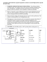
To connect the space temperature sensor (Fig. 10):
1. Using a 20 AWG twisted pair conductor cable rated for
the application, connect 1 wire of the twisted pair to one
SEN terminal and connect the other wire to the other
SEN terminal located under the cover of the space
temperature sensor.
2. Connect the other ends of the wires to terminals 5 and 6
on TB5 located in the unit control box.
IMPORTANT: A shorted CCN bus cable will prevent some
routines from running and may prevent the unit from start-
ing. If abnormal conditions occur, unplug the connector. If
conditions return to normal, check the CCN connector and
cable. Run new cable if necessary. A short in one section of
the bus can cause problems with all system elements on the
bus.
THERMISTOR
PIN
CONNECTION
POINT
THERMISTOR INPUT
LWT J8-13,14 (MBB) Cooler Leaving Fluid
EWT J8-11,12 (MBB) Cooler Entering Fluid
RGTA
J8-1,2 (MBB) Circuit A Return Gas
Temperature
RGTB
J8-3,4 (MBB) Circuit B (035-060 only)
Return Gas Temperature
OAT
J8-7,8 (MBB) Outdoor-Air Temperature
Sensor
SPT
J8-5,6 (MBB)
TB5-5,6
Accessory Remote Space
Temperature Sensor or
Dual LWT Sensor
DTT
J6-1,2 (AUX) Discharge Temperature
Thermistor
LWT — Leaving Water Temperature
MBB — Main Base Board
STATUS SWITCH PIN CONNECTION POINT
Chilled Water Pump 1 J7-1,2
Chilled Water Pump 2 J7-3,4
Remote On/Off LVT-13,14
Cooler Flow Switch J7-9,10
Compressor Fault Signal, A1 J9-11,12
Compressor Fault Signal, A2 J9-5,6
Compressor Fault Signal, B1 J9-8,9
Compressor Fault Signal, B2 J9-2,3
RELAY
NO.
DESCRIPTION
K1
Energize Compressor A1 (010-030)
Energize Compressor A1 and Condenser Fan Contac-
tor 3 (055,060)
K2 Energize Compressor A2 (all but 010, 015 60 Hz)
K3 Energize Chilled Water Pump 1 Output
K4 Energize Chilled Water Pump 2 Output
K5
Energize Compressor B1 (035-050)
Energize Compressor B1 and Condenser Fan Contac-
tor 3 (055,060)
K6 Energize Compressor B2 (035-060)
K7 Alarm Relay
K8 Cooler/Pump Heater
K9 Energize Condenser Fan Contactor 1 (018-060)
K10 Energize Condenser Fan Contactor 2 (018-060)
K11 Minimum Load Valve
MANUFACTURER
PART N O.
Regular Wiring Plenum Wiring
Alpha 1895 —
American A21451 A48301
Belden 8205 884421
Columbia D6451 —
Manhattan M13402 M64430
Quabik 6130 —
/