Eurotherm TE10P User manual
- Category
- Measuring, testing & control
- Type
- User manual
This manual is also suitable for

iTE10P User manual HA175960ENG Issue 2.2 Printed in France
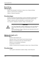
Active power controller
TE10P
Control of all types of single-phase load
- optional digital communications
User Manual
(16A to 400A rated units)
©Copyright Eurotherm Automation 1998
All rights reserved. All reproduction or transmission in any form or using any procedure (electronic or
mechanical, including photocopying or recording) without written authorisation from EUROTHERM
AUTOMATION is strictly prohibited.
EUROTHERM AUTOMATION has made every effort to ensure that the specification given in this manual is
as accurate and up to the minute as possible. However, in order to maintain our Ôleading edgeÕ, it may be
necessary to make certain changes or omissions to our specification. We cannot be held responsible for
any damage to persons or property or for any financial loss or costs arising from this.

TE10P User manualii

iiiTE10P User manual
CONTENTS
Page
RELEVANTEUROPEAN DIRECTIVES . . . . . . . . . . . . . . . . . . . . . . .iv
Chapter 1 IDENTIFYING THE CONTROLLER . . . . . . . . . . . . . .1-1
Chapter 2 INSTALLATION . . . . . . . . . . . . . . . . . . . . . . . . . . . . . .2-1
Chapter 3 WIRING . . . . . . . . . . . . . . . . . . . . . . . . . . . . . . . . . . . . .3-1
Chapter 4 OPERATION . . . . . . . . . . . . . . . . . . . . . . . . . . . . . . . . .4-1
Chapter 5 DIGITALCOMMUNICATIONS (option) . . . . . . . . . . .5-1
Chapter 6 CONFIGURATION . . . . . . . . . . . . . . . . . . . . . . . . . . . .6-1
Chapter 7 COMMISSIONING PROCEDURE . . . . . . . . . . . . . . . .7-1
Chapter 8 ALARMS . . . . . . . . . . . . . . . . . . . . . . . . . . . . . . . . . . . .8-1
Chapter 9 MAINTENANCE . . . . . . . . . . . . . . . . . . . . . . . . . . . . . .9-1
Chapter 10 TYPICALAPPLICATIONS . . . . . . . . . . . . . . . . . . . . .10-1
INDEX . . . . . . . . . . . . . . . . . . . . . . . . . . . . . . . . . . . . . . . . . . . .11-1

TE10P User manualiv
RELEVANT EUROPEAN DIRECTIVES
CE MARKING AND SAFETY
TE10Pproducts carry the CE mark in compliance with the essential requirements of the
European Low Voltage Directive 73/23/EEC of 19/2/73, amended by the Directive
93/68/EEC of 22/7/93
For safety purposes, TE10Pproducts installed and used in compliance with this User
Manual meet the essential requirements of the European Low Voltage Directive.
DECLARATION OF CE CONFORMITY
Availability
Adeclaration of CE conformity is available on request.
Validation by Competent Body
Eurotherm has validated the compliance of TE10Pproducts with the European Low
Voltage Directive and with EMC test standards (see following page) through product
design and laboratory testing.
These tests are listed in a Technical Construction File validated by the LCIE (Central
Laboratory for the Electrical Industries), a Recognised Competent Body.

vTE10P User manual
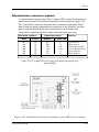
ELECTROMAGNETIC COMPATIBILITY (EMC)
(For industrial environments only, must not be used in domestic environments)
Eurotherm certifies that TE10Pproducts, installed and used in compliance with
this User Manual, meet the following EMC test standards and enable the system
which incorporates them to comply with the EMC Directive, as far as the TE10P
products are concerned.
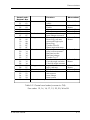
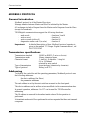
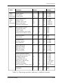
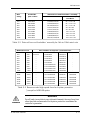
Test standards
Tests EMC test standards
Immunity Generic standard EN50082-2
Electrostatic discharge EN 61000-4-2 (06/1995)
Fast transients EN 61000-4-4 (01/1995)
RF electromagnetic fields ENV 50140, ENV 50141 and
ENV 50204
Emission Radiated & Conducted EN 55011 Class A (1991)
The choice of standard for the Conducted Emission depends on
the application:
á EN 50081-2 Class A (1991)
- Without external filter in Burst-firing mode for resistive
load ² 100A
- With an external series filter for Phase angle mode
á IEC 1800-3 (EN 61800-3 1996)
- Without external filter. Applies to 2nd environment.
Internal EMC filters
Internal EMC filters are incorporated as an option in the TE10Pthyristor units to
reduce conducted emission in Burst-firing mode for resistive loads ≤100Ain
accordance with the corresponding test standard.
To reduce conducted emissions associated with certain thyristor unit applications,
Eurotherm can supply external filters.
EMC Guide
In order to help you reduce the effects of electromagnetic interference depending
on the product installation, Eurotherm can supply you with the ‘Electromagnetic
Compatibility’Installation Guide (Ref: HA025464 ENG).

TE10P User manualvi
SCOPE OF MANUAL
This TE10PUser Manual (Ref: HA175960 ENG) is intended for use with the
TE10Prange of power controllers rated between 16Aand 400Ain two mechanical
formats.
Issue 2.0 of the manual is intended for products manufactured from August 1999.
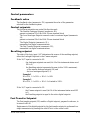
PRECAUTIONS
Important safety precautions and special information are indicated in the text of
the manual by two symbols:
This symbol means that failure to take note of the information given in
this manual may have serious consequences for the safety of personnel
and may even result in electrocution.
This symbol means that failure to take note of the information may
have serious consequences for the installation or lead to the incorrect
operation of the power unit.
These symbols must be observed for particular points.
However the whole of the manual remains applicable.
Personnel
The installation, configuration, commissioning and maintenance of the power
controller must only be carried out by personnel qualified and trained to work
with low voltage electrical equipment in an industrial environment.
Independent alarm
Given the safety regulations concerning personnel and property, and the value of
the equipment controlled by TE10Pthyristor power units, we recommend the use
of an independent safety device (alarm), which must be tested regularly.
Eurotherm can supply appropriate equipment.
Further information
For any further information, or if in doubt, please contact Eurotherm Controls
where qualified staff are available to advise or assist you with the commissioning
of your installation.
DANGER
WARNING

1-1
Identifying the controller
TE10P User manual
Chapter 1
IDENTIFYING THE TE10P POWER CONTROLLER
Page
GENERALINTRODUCTION . . . . . . . . . . . . . . . . . . . . . . . . . . . . .1-2
TECHNICALSPECIFICATION . . . . . . . . . . . . . . . . . . . . . . . . . . .1-5
CURRENTDERATING . . . . . . . . . . . . . . . . . . . . . . . . . . . . . . . . . .1-9
PRODUCTCODE . . . . . . . . . . . . . . . . . . . . . . . . . . . . . . . . . . . . .1-10
EXAMPLE OF PRODUCTCODE . . . . . . . . . . . . . . . . . . . . . . . .1-12

TE10P User manual
Identifying the controller
1-2
CHAPTER 1 IDENTIFYING THE CONTROLLER
GENERAL INTRODUCTION
The TE10Prange of thyristor power units are electrical power controllers
designed for the control of active power in all types of industrial single-phase
loads (with the exception of purely capacitative loads*).
TE10Ppower units, in two mechanical versions, control currents between 16A
and 400A.
The nominal voltage (operating voltage) ranges from 100Vto 500V.
Units rated from 16Ato 100Acomprise of two channels; one controlled by
thyristors and the other a direct link from input to output; 125Ato 400Arated
units comprise one channel controlled by thyristors.
The TE10Poffers all the operating modes necessary to select precise control of
complex loads (platinum, molybdenum disilicide, silicon carbide...) and to
optimise firing modes in order to reduce flickering of short-wave infrared
elements.
Configuration of the parameters for control, operation and thyristor firing mode
can be implemented from the controller front panel or by means of optional digital
communications.
Depending on the configuration, the TE10Pmay be used with analogue or logic
signals or may be driven remotely by digital communications (option).
Supervisory monitoring uses the RS485 (or RS422) digital link.
Data exchange takes place using the Modbus® or Profibus-DPprotocols.
The status of digital communications is indicated by LEDs.
Adefault mode is provided to control the unit using an external potentiometer or
analogue signal.
Aseven-segment four-digit display is used for local adjustment (initial
commissioning) and rapid diagnosis of the state of the controller, its configuration
and the state of the alarms.
Access to the scrolling menu on the display is provided by means of a push button
on the front panel.
Configuration mini-switches (accessible by opening the access doors), together
with four potentiometers to adjust the principal operating parameters, are located
on the front panel.
Adiagnostic connector is used to connect a Eurotherm 260 diagnostic unit, to test
or control 20 electrical signals.
Current or voltage monitoring reduces or stops thyristor firing if limits are
exceeded (depending on the configuration). Load failure detection adapts itself to
standard or complex loads.
Faults on the supply, load, current or voltage are signalled by the display, by the
alarm relay and via digital communications.
* Consult Eurotherm

1-3
Identifying the controller
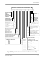
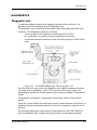
TE10P User manual
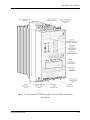
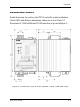
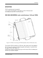
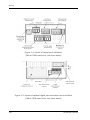
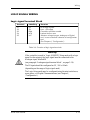
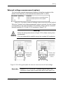
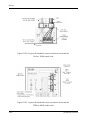
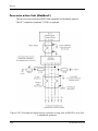
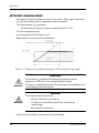
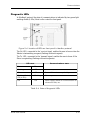
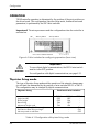
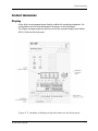
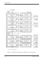
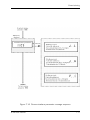
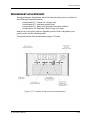
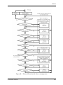
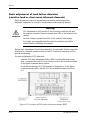
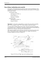
Figure 1-1 Overview of TE10P controller (16A to 100A rated units,
all options)

TE10P User manual
Identifying the controller
1-4
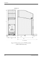
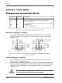
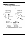
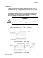
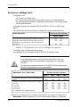
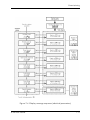
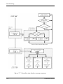
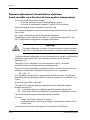
Figure 1-2 Overview of TE10P controller (125A to 400A rated units,
all options)

1-5
Identifying the controller
TE10P User manual
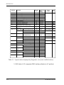
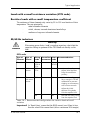
TECHNICAL SPECIFICATION
The TE10Pseries of power controllers are designed to control all types of single-
phase industrial loads (except for purely capacitative loads) by means of
thyristors.
Danger!
Asafety device ensuring electrical isolation between the equipment
and the supply must be installed in order to permit safe maintenance.
Athyristor is not an isolating device. Touching a load terminal, even
with zero load current, is as dangerous as touching mains live. It is the
user’s responsibility to ensure, before commissioning the controller,
that all the nominal ratings of the controller are compatible with the
conditions of use and the installation.
Warning!
It is the user’s responsibility to ensure, before commissioning the
controller, that all the nominal ratings of the controller are compatible
with the conditions of use and the installation.
CE Marking*
Electrical safety Complies with European Low Voltage Directive 73/23 EEC
TE10Pproducts carry the CE mark in compliance with the
essential requirements of this Directive.
Electromagnetic Compatibility*
Immunity Complies with EN 50082-2, EN 61000-4-2,
EN 61000-4-4, ENV50204, ENV50140, ENV 50141
Radiated emission Complies with EN 550011 Standard Class A
Conducted emission Complies with EN 50081-2 Standard :
without external filter in Burst-firing mode for resistive
loads and up to 100Anominal
with external series filter for Phase angle mode,
Complies with IEC 1800-3 Standard
(EN 61800-3): without filter.
Applies to second (industrial) environment.
An internal EMC filter (FILToption for units rated ≤100A) reduces radio
frequency conducted interference.
* Controller installed and used in accordance with this Manual (see chapter on European Directives)
Warning!
In order to maintain our ‘leading edge’, Eurotherm may have to make
certain changes to specifications without prior notice. For any further
information, or if in doubt please contact your nearest Eurotherm
office.
DANGER
WARNING
WARNING

TE10P User manual
Identifying the controller
1-6
Power
Nominal current (at 45°C) 16Ato 400Adepending on product code
Nominal voltage 100Vto 500V(+10%, -15%) depending on product code
Inhibition below 80% of calibrated voltage.
Supply frequency Between 40Hz and 70Hz, automatic selection.
Inhibited outside 40Hz to 70Hz.
Dissipated power 1.3W(approx.) per amp
Cooling Natural convection: ≤ 100A. Permanently fan cooled: ≥ 125A.
Fan (≥ 125A) 25VAconsumption
Supply voltage 115Vor 230Vdepending on product code
Load Single phase: resistive, short-wave infrared, transformer primary,
inductive, or temperature dependent loads
Not suitable for purely capacitive loads
Control signals
Power supply Self-supplied from main supply, or separate power supply of 115Vor
230V(+10%; -15%)
Consumption: 10VA
Control type Analogue, Logic or Digital communications
Analogue signals Remote analogue setpoint and limiting signals
0-5Vor 0-10V(input impedance ≥ 100kΩ),
0-20mAor 4-20mA(input impedance 250Ω)
Local setpoint: 0-5V(input impedance ≥ 100kΩ) and / or manual
control potentiometer.
Logic signals Max values: 5V, 10Vor 20mAin Logic mode only; ‘on’state ≥ 50%;
off state ≤ 25%.
Enable, Reset, Default type: 5V(10kΩ input)
‘active’state > 4V; ‘non-active’state < 1V.
User output 5Vdc (5mAmax).
Firing modes
Initial start-up Safety ramp by means of selectable phase angle
start (not availablr for Advanced Single-cycle).
Zero crossing firing · Burst-firing 1, 8, 16, or 128 cycles
· Logic (On/Off)
For these two modes, the following are available:
- elimination of momentary over-currents for inductive loads (delayed
firing at start of each cycle)
- soft-start (firing angle variation) adjustable at 2, 4, 8, 16, 32 or 64
cycles.
· Advanced Single-cycle
Firing by whole cycles separated by half cycles of non-firing (without
DC component).
Firing angle variation · Phase angle
Alinear ramp (if selected) at setpoint change.
Duration of ramp is adjustable from 0 to 65s for a setpoint change
from 0 to 100% using potentiometer on front panel.

1-7
Identifying the controller
TE10P User manual
Control function
Feedback parameter · Active power (P) calculated from instantaneous measurements
· RMS load voltage (V) or current (I)
· Load voltage (V
2
) or load current (I
2
) squared
· Open loop
· Transfer of controlled parameters: I
2
↔ V
2
or I
2
↔ P
Control linearity Better than ±1% of full scale
Stability ±1% of full scale with variations in:
- load impedance ±30%;
- supply voltage +10%, -15%
- temperature from 0 to 50°C
Response time In Phase angle: 250ms typically
In Logic: 60ms approx.
In Burst-firing depends on base time selected (T
B
):
300ms (TB = 1 cycle); 1.6s (TB = 8 cycles);
3.2s (TB = 16 cycles); 26s (TB = 128 cycles).
Retransmission · Isolated analogue output at 0 to 10Vor 4 to 20mA(option):
Control value (as standard), or one of parameters selected by digital
communications (controlled parameter, load power, load current or
voltage).
Precision better than ±1%
In Logic, stability guaranteed for a control signal cycle time:
0.5s < t < 20min.
· Display on front panel (all operating parameters)
· Digital communications (option)
Setpoint · Analogue: adjustment using a single potentiometer or in cascade with
an external analogue signal (0 to 5V, 0 to 10V, 0 to 20mAor
4 to 20mA)
· Digital (option): adjustment via communications bus
I / VLimit Current monitoring whatever the configuration
(for short-wave infrared available only in Phase angle).
Current limit action by reducing firing angle (except in Advanced
Single-cycle) or by stopping thyristor firing.
Voltage limit by reducing firing angle selectable only in Phase angle,
accompanied by limit in load current to 100% non-adjustable.
Limit threshold adjustable using a single front panel potentiometer or
in cascade with an external analogue signal (0 to 5V, 0 to 10V,
0 to 20mAor 4 to 20mA) and in cascade with the limit digital setpoint
(option) .
Digital communications (option)
Bus Serial link RS422 or RS485 (isolated)
Protocol PROFIBUS-DPor MODBUS®
Transmission rate Modbus: configurable in 9.6kbaud or 19.2kbaud
Profibus-DP: automatic recognition up to 1.5Mbaud.
Default mode The default configuration is determined by mini-switches or memory
(user selection).

TE10P User manual
Identifying the controller
1-8
Alarms
Supply · Absence of supply voltage (≤ 30% of nominal voltage): firing
shutdown
· Under-voltage: firing shutdown below 80% of controller operating
voltage
· Over-voltage: alarm on voltage 10% greater than controller operating
voltage
· Frequency above 70Hz or below 40Hz: firing shutdown
Current Current exceeds limit threshold by 10%, if firing shutdown action is
selected.
Load 20% increase in load impedance compared with calculated value
derived from voltage / current measurement (static adjustment) or
continuously calculated (dynamic adjustment)
Static adjustment of load failure detection using push button on front
panel or via digital communications
With load failure detection controlled in this way, breakage detection
is ensured for at least one in six identical elements wired in parallel.
Thyristors · Thermal monitoring: firing shutdown if thermo-contacts open for
fan-cooled units (125Ato 400Anominal).
· Thyristor short-circuit: firing shutdown
Alarm information Alarm type and degree of severity are permanently displayed: data
available via digital communications (option), relay signalling (the
alarm relay is programmable via comms).
Diagnostics Connector for diagnostic unit permits adjustment and control of
thyristor unit by means of 20 test signals
Environment
Operating temperature 0°C to +45°C at 2000m max. altitude
(see current derating curves)
Storage temperature -10°C to +70°C
Thyristor protection Internal MOV(varistor) and RC snubber
High-speed fuse:
- external for 16Ato 100Arated units
- internal for 125Ato 400Arated units
Protection IP20 in accordance with IEC 529 on front panel, door closed for
≥ 125Arated units
External wiring To be carried out in compliance with Standard IEC 364
Operating atmosphere Non-explosive, non-corrosive & non-conductive
Humidity RH: 5% to 95%, non-condensing and non-streaming
Pollution Pollution degree 2 permissible, defined by IEC 664
Dimensions (16Ato 100A) 225mm (H) x 116mm (W) x 169mm (D)
(125Ato 400A) 470mm (H) x 133mm (W) x 260mm (D)
Weight 16Ato 100A: 3.2kg 125Ato 400A: 11.5kg

1-9
Identifying the controller
TE10P User manual
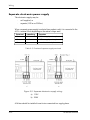
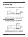
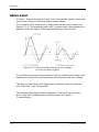
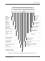
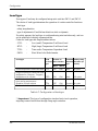
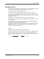
CURRENT DERATING
The nominal currents of TE10Pcontrollers are defined at the ambient temperature
of 45°C.
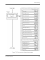
Figure 1-3 Current derating for TE10P controllers
(16A to 100A rated units)
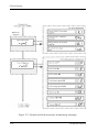
Figure 1-4 Current derating for TE10P controllers
(125A to 400A rated units)

TE10P User manual
Identifying the controller
1-10
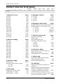
PRODUCT CODE FOR TE10P RANGE
1. Nominal current Code
16 amps 16A
20 amps 20A
25 amps 25A
32 amps 32A
40 amps 40A
50 amps 50A
63 amps 63A
80 amps 80A
100 amps 100A
125 amps 125A
160 amps 160A
200 amps 200A
250 amps 250A
315 amps 315A
400 amps 400A
2. Nominal voltage Code
100 volts 100V
115 volts 115V
200 volts 200V
230 volts 230V
240 volts 240V
277 volts 277V
380 volts 380V
400 volts 400V
415 volts 415V
440 volts 440V
460 volts 460V
480 volts 480V
500 volts 500V
3. Auxiliary supply Code
Self-supplied AUTO
Separate external power supply:
115 volts 115V
230 volts 230V
4. Fan supply Code
Without fan (16A to 100A) 000
115V supply (³ 125A) 115
230V supply (³ 125A) 230
5. Analogue setpoint Code
0 - 5 volts 0V5
0 - 10 volts 0V10
0 - 20 mA 0mA20
4 - 20 mA 4mA20
6. Analogue setpoint limit Code
By potentiometer on front panel only SPOT
By potentiometer and external signal:
0 - 5 volts S0V5
0 - 10 volts S0V10
0 - 20 mA S0mA20
4 - 20 mA S4mA20
7. Thyristor firing mode Code
Logic (All or nothing) LGC
Phase angle PA
Advanced Single-cycle SCA
Burst-firing with Base time of:
1 cycle FC1
8 cycles FC8
16 cycles C16
128 cycles 128
8. Soft-start / Ramp Code
Soft-start (Burst-firing and Logic) or
Ramp (Phase angle) URP
Without Soft-start / without Ramp NRP
9. Safety ramp Code
Initial active safety ramp (except in
Advanced Single-cycle) AR
Without initial safely ramp NR
10. Load type Code
Resistive load with low temperature
coefficient LTCL
Resistive load with high temperature
coefficient: Molybdenum, Platinum,
Tungsten, Molybdenum disilicide HTCL
Variable load as a function of time
and / or temperature: Silicon carbide TTDL
Short-wave infrared elements SWIR
Analogue Setpoint Firing Ramp Safety Load
Current Voltage Auxiliary Fan Setpoint Limit Mode Start Ramp Type
TE10P/ / / / / / / / / / /

1-11
Identifying the controller
TE10P User manual
11. Controlled parameter Code
Active power P
RMS load current IE
RMS load voltage VE
RMS load current squared I2
RMS load voltage squared V2
Open loop OL
Transfer of controlled parameters:
I
2
↔ V
2
I2 V2
I
2
↔ P I2P
12. Current / voltage limit* Code
Firing shutdown if current limit
threshold is exceeded ICHO
Current limit by firing angle
reduction ILI
Voltage limit by firing angle
reduction (available only in
phase angle) VLI
* For short-wave infrared,
available only in Phase angle
* For load with code HTCL:
ICHO in SCA firing mode and
ILI in other firing modes
13. I or V limiting signal Code
By potentiometer on front panel
only LPOT
By potentiometer and external
signal:
0 - 5V L0V5
0 - 10V L0V10
0 - 20mA L0mA20
4 - 20mA L4mA20
14. Mounting Code
Bulkhead installation BKD
DIN rail mounting (² 100A rated
units) DIN
15. Alarm relay Code
Alarm relay contacts:
Closed in alarm state NC
Open in alarm state NO
16. Communications protocol Code
Without digital communications 000
Modbus¨ MOP
Profibus-DP PFP
17. Transmission rate Code
Modbus¨ protocol:
Read-only at 9.6kbaud R96
Read-only at 19.2kbaud R192
Read-write at 9.6 kbaud W96
Read-write at 19.2kbaud W192
Profibus protocol:
Read-only up to 1.5Mbaud RAUT
Read-write up to 1.5Mbaud WAUT
18. Communications defaults Code
Configuration set by mini-switches CSW
Configuration written in non-volatile
memory CEP
19. Options Code
Isolated analogue retransmission
0 - 10V R0V10
4 - 20mA R4mA20
Sub-miniature communications
connector (9 pin) DB9
External load current measurement IEXT
External load voltage measurement
(select from the codes available
in the nominal voltage field) ááá V
Internal EMC filter (²100A) in
Burst-firing mode FILT
Fuse-blown microswitch (³125A) FUMS
Without internal fuse (³125A) NOFUSE
20. Manual language Code
French FRA
English ENG
Controlled Limiting Alarm Comms Manual
Parameter Limit Signal Mounting Relay Protocol Rate Default Options Language
/ / / / / / / / / / 00

TE10P User manual
Identifying the controller
1-12
WARNING
EXAMPLE OF PRODUCT CODE
TE10P controller and installation parameters
Nominal load current 80 amps
Nominal voltage 380 volts
Electronics supply Self-supplied
Analogue setpoint signal 0 to 10 volts
Analogue setpoint limit By potentiometer only on front panel
Firing mode 16 cycle burst-firing with soft-start
Safety ramp Initial ramp
Load Resistive with low temperature coefficient
Controlled parameter Active power
Limit type Current; by reducing firing angle
Limit signal Adjustment by potentiometer only on front panel
Mounting On DIN rails
Communications protocol Modbus®
Transmission rate Digital communications in read-write at 9600bauds
Communications default Configuration by mini-switches
Options Isolated retransmission output of 0 to 10 volts
External load voltage measurement 100V
Manual language English
Controller code:
TE10P / 100A / 380V / AUTO / 000 / 0V10 / SPOT / C16 / URP / AR / LTCL /
P / ILI / LPOT / DIN / NO / MOP / W96 / CSW / ROV10 / 100V / ENG / 00
Warning!
Following any reconfiguration on the part of the user, there is no
guarantee that the controller will correspond to the label information.
The operating voltage of the controller (the calibration voltage) is
considered as the nominal voltage of the controller.
The nominal voltage of the TE10Pcontroller must be as close as
possible to the supply voltage used in order to eliminate problems of
the controller not operating if the voltage drops below 80% of the
nominal voltage.

2-1
Installation
TE10P User manual
Chapter 2
INSTALLATION
Page
INSTALLATION - SAFETY . . . . . . . . . . . . . . . . . . . . . . . . . . . . . .2-2
DIMENSIONALDETAILS . . . . . . . . . . . . . . . . . . . . . . . . . . . . . . .2-3
MOUNTING . . . . . . . . . . . . . . . . . . . . . . . . . . . . . . . . . . . . . . . . . . .2-5
DIN RAILMOUNTING . . . . . . . . . . . . . . . . . . . . . . . . . . . . . . . .2-5
BULKHEAD MOUNTING . . . . . . . . . . . . . . . . . . . . . . . . . . . . . .2-6

TE10P User manual
Installation
2-2
CHAPTER 2 INSTALLATION
INSTALLATION - SAFETY
Danger !
TE10Punits must be installed by personnel trained to work with low
voltage electrical equipment in an industrial environment.
Units must be installed in fan-cooled electrical cabinets, to ensure that
condensation and pollution are excluded.
The cabinet must be closed and bonded to the safety earth in
accordance with Standards IEC 364 or current national Standards.
For installations which are fan-cooled, it is recommended that a fan-failure
detection device or a thermal safety cut-out should be fitted in the cabinet.
TE10P units may be bulkhead or DIN-rail mounted (≤100A).
The units must be mounted with the heatsink positioned vertically, with no
obstructions above or below which could inhibit or impede airflow.
If several units are mounted in the same cabinet, they must be arranged in such a
way that air expelled from one cannot be drawn into the unit located above it.
Warning!
The units are designed to be used at an ambient temperature not
exceeding 45°C.
Leave a minimum gap of 5cm between two units placed side by side.
Excessive overheating of the unit may lead to incorrect operation of the
unit. This may in turn cause damage to the components.
The TE10Prange of thyristor units rated between 125Aand 400Ahave
permanent fan cooling.
DANGER
WARNING
Page is loading ...
Page is loading ...
Page is loading ...
Page is loading ...
Page is loading ...
Page is loading ...
Page is loading ...
Page is loading ...
Page is loading ...
Page is loading ...
Page is loading ...
Page is loading ...
Page is loading ...
Page is loading ...
Page is loading ...
Page is loading ...
Page is loading ...
Page is loading ...
Page is loading ...
Page is loading ...
Page is loading ...
Page is loading ...
Page is loading ...
Page is loading ...
Page is loading ...
Page is loading ...
Page is loading ...
Page is loading ...
Page is loading ...
Page is loading ...
Page is loading ...
Page is loading ...
Page is loading ...
Page is loading ...
Page is loading ...
Page is loading ...
Page is loading ...
Page is loading ...
Page is loading ...
Page is loading ...
Page is loading ...
Page is loading ...
Page is loading ...
Page is loading ...
Page is loading ...
Page is loading ...
Page is loading ...
Page is loading ...
Page is loading ...
Page is loading ...
Page is loading ...
Page is loading ...
Page is loading ...
Page is loading ...
Page is loading ...
Page is loading ...
Page is loading ...
Page is loading ...
Page is loading ...
Page is loading ...
Page is loading ...
Page is loading ...
Page is loading ...
Page is loading ...
Page is loading ...
Page is loading ...
Page is loading ...
Page is loading ...
Page is loading ...
Page is loading ...
Page is loading ...
Page is loading ...
Page is loading ...
Page is loading ...
Page is loading ...
Page is loading ...
Page is loading ...
Page is loading ...
Page is loading ...
Page is loading ...
Page is loading ...
Page is loading ...
Page is loading ...
Page is loading ...
Page is loading ...
Page is loading ...
Page is loading ...
Page is loading ...
Page is loading ...
Page is loading ...
Page is loading ...
Page is loading ...
Page is loading ...
Page is loading ...
Page is loading ...
Page is loading ...
Page is loading ...
Page is loading ...
Page is loading ...
Page is loading ...
Page is loading ...
Page is loading ...
Page is loading ...
Page is loading ...
Page is loading ...
Page is loading ...
Page is loading ...
Page is loading ...
Page is loading ...
Page is loading ...
Page is loading ...
Page is loading ...
Page is loading ...
Page is loading ...
Page is loading ...
Page is loading ...
Page is loading ...
Page is loading ...
Page is loading ...
Page is loading ...
Page is loading ...
Page is loading ...
Page is loading ...
Page is loading ...
Page is loading ...
Page is loading ...
Page is loading ...
Page is loading ...
Page is loading ...
Page is loading ...
Page is loading ...
Page is loading ...
Page is loading ...
Page is loading ...
Page is loading ...
Page is loading ...
Page is loading ...
Page is loading ...
Page is loading ...
Page is loading ...
Page is loading ...
Page is loading ...
Page is loading ...
Page is loading ...
Page is loading ...
Page is loading ...
Page is loading ...
Page is loading ...
Page is loading ...
Page is loading ...
Page is loading ...
Page is loading ...
Page is loading ...
Page is loading ...
Page is loading ...
Page is loading ...
Page is loading ...
Page is loading ...
Page is loading ...
Page is loading ...
Page is loading ...
Page is loading ...
Page is loading ...
Page is loading ...
Page is loading ...
Page is loading ...
Page is loading ...
Page is loading ...
Page is loading ...
Page is loading ...
Page is loading ...
Page is loading ...
Page is loading ...
Page is loading ...
Page is loading ...
Page is loading ...
Page is loading ...
Page is loading ...
Page is loading ...
-
 1
1
-
 2
2
-
 3
3
-
 4
4
-
 5
5
-
 6
6
-
 7
7
-
 8
8
-
 9
9
-
 10
10
-
 11
11
-
 12
12
-
 13
13
-
 14
14
-
 15
15
-
 16
16
-
 17
17
-
 18
18
-
 19
19
-
 20
20
-
 21
21
-
 22
22
-
 23
23
-
 24
24
-
 25
25
-
 26
26
-
 27
27
-
 28
28
-
 29
29
-
 30
30
-
 31
31
-
 32
32
-
 33
33
-
 34
34
-
 35
35
-
 36
36
-
 37
37
-
 38
38
-
 39
39
-
 40
40
-
 41
41
-
 42
42
-
 43
43
-
 44
44
-
 45
45
-
 46
46
-
 47
47
-
 48
48
-
 49
49
-
 50
50
-
 51
51
-
 52
52
-
 53
53
-
 54
54
-
 55
55
-
 56
56
-
 57
57
-
 58
58
-
 59
59
-
 60
60
-
 61
61
-
 62
62
-
 63
63
-
 64
64
-
 65
65
-
 66
66
-
 67
67
-
 68
68
-
 69
69
-
 70
70
-
 71
71
-
 72
72
-
 73
73
-
 74
74
-
 75
75
-
 76
76
-
 77
77
-
 78
78
-
 79
79
-
 80
80
-
 81
81
-
 82
82
-
 83
83
-
 84
84
-
 85
85
-
 86
86
-
 87
87
-
 88
88
-
 89
89
-
 90
90
-
 91
91
-
 92
92
-
 93
93
-
 94
94
-
 95
95
-
 96
96
-
 97
97
-
 98
98
-
 99
99
-
 100
100
-
 101
101
-
 102
102
-
 103
103
-
 104
104
-
 105
105
-
 106
106
-
 107
107
-
 108
108
-
 109
109
-
 110
110
-
 111
111
-
 112
112
-
 113
113
-
 114
114
-
 115
115
-
 116
116
-
 117
117
-
 118
118
-
 119
119
-
 120
120
-
 121
121
-
 122
122
-
 123
123
-
 124
124
-
 125
125
-
 126
126
-
 127
127
-
 128
128
-
 129
129
-
 130
130
-
 131
131
-
 132
132
-
 133
133
-
 134
134
-
 135
135
-
 136
136
-
 137
137
-
 138
138
-
 139
139
-
 140
140
-
 141
141
-
 142
142
-
 143
143
-
 144
144
-
 145
145
-
 146
146
-
 147
147
-
 148
148
-
 149
149
-
 150
150
-
 151
151
-
 152
152
-
 153
153
-
 154
154
-
 155
155
-
 156
156
-
 157
157
-
 158
158
-
 159
159
-
 160
160
-
 161
161
-
 162
162
-
 163
163
-
 164
164
-
 165
165
-
 166
166
-
 167
167
-
 168
168
-
 169
169
-
 170
170
-
 171
171
-
 172
172
-
 173
173
-
 174
174
-
 175
175
-
 176
176
-
 177
177
-
 178
178
-
 179
179
-
 180
180
-
 181
181
-
 182
182
-
 183
183
-
 184
184
-
 185
185
-
 186
186
-
 187
187
-
 188
188
-
 189
189
-
 190
190
-
 191
191
-
 192
192
-
 193
193
-
 194
194
-
 195
195
-
 196
196
-
 197
197
-
 198
198
-
 199
199


Eurotherm TE10P User manual
- Category
- Measuring, testing & control
- Type
- User manual
- This manual is also suitable for
Ask a question and I''ll find the answer in the document
Finding information in a document is now easier with AI
Related papers
-
Eurotherm PC3000 Owner's manual
-
-
-
-
-
-
-
-
-
Other documents
-
 Tough Leads 13a User manual
-
HANYOUNG NUX TPR2 Owner's manual
-
Shinko PA-200 series User manual
-
 Kuhse KEA 112 MOBL Operating instructions
-
YASKAWA General Inverter Drives User manual
-
IFM AC5223 Operating instructions
-
HP 61010A User manual
-
Vemer PC1R MICRO User manual
-
 Eurotherm controls 847 User manual
-
 CD Automation CD3000M 1PH User manual


