Page is loading ...

© Copyright Eurotherm Automation 1996
All rights reserved. All reproduction or transmission in any form or using any procedure (electronic or mechanical, including photocopying and
recording) without the written permission of EUROTHERM AUTOMATION is strictly prohibited. EUROTHERM AUTOMATION have taken
particular care to ensure the accuracy of these specifications. However, in order to maintain our technological lead, we are dedicated to the
continual improvement of our products and this may lead to modifications or omissions in the current specifications. We cannot be held
responsible for any material or bodily damage, losses or costs incurred.
Printed in France 05/96 HA 175076 Issue 1
Thyristor Power units
and
Driver units
470
series
Single-phase resistive and
inductive load
true power control
User
Manual

Printed in France 05/96 HA 175076 Issue 1
This symbol means that failure to take note of the
information may have serious consequences for the
safety of personnel and may even result in the risk
of electrocution.
This symbol means that failure to take note of the
information may
• have serious consequences for the installation
• result in the incorrect functioning of the power unit.
Important precautions and special information are indicated in the manual by
two symbols:
These marks must indicate specific points.
The entire manual remains applicable.
As a result of the constant improvement of its products, Eurotherm
may modify these specifications without warning.
For any further information and if in doubt, please contact your EUROTHERM
office where technicians are at your disposal should you require advice or
assistance with the commissioning of your installation.
Printed in France 05/96 HA 175076 Issue 1
It is the responsibility of the user and it is highly recommended, given the value
of the equipment controlled using 470, to install independent safety devices.
This alarm must be tested regularly.
Eurotherm can supply suitable equipment.
This symbol means that failure to take note of the
information may have serious consequences for the
safety of personnel and may even result in the risk
of electrocution.
This symbol means that failure to take note of the
information may
• have serious consequences for the installation
• result in the incorrect functioning of the power unit.
Important precautions and special information are indicated in the manual by
two symbols:
These marks must indicate specific points.
The entire manual remains applicable.
As a result of the constant improvement of its products, Eurotherm
may modify these specifications without warning.
For any further information and if in doubt, please contact your EUROTHERM
office where technicians are at your disposal should you require advice or
assistance with the commissioning of your installation.
It is the responsibility of the user and it is highly recommended, given the value
of the equipment controlled using 470, to install independent safety devices.
This alarm must be tested regularly.
Eurotherm can supply suitable equipment.
!
WARNING
CAUTION
WARNING
!
CAUTION
The installation, configuration, commissioning and maintenance of the power unit
must only be performed by a person qualified and authorised to perform work
in an industrial low voltage electrical environment.
The installation, configuration, commissioning and maintenance of the power unit
must only be performed by a person qualified and authorised to perform work
in an industrial low voltage electrical environment.

Printed in France 05/96 HA 175076 Issue 1
Printed in France 05/96 HA 175076 Issue 1
In order to guarantee the best service, Eurotherm has validated the compliance of
the 470 products with these test standards through design and laboratory
tests that have been validated with a Technical Construction File by a Competent
Body, LCIE (Laboratoire Central des Industries Électriques).
To reduce the conducted emissions that occur when using thyristor units, Eurotherm can
supply external filters.
Nominal current of 470 Serial filter order code
25 A to 60 A FILTER/TRI/63A/00
75 A and 100 A FILTER/TRI/100A/00
150 A FILTER/TRI/160A/00
The 470 products are considered as components without any direct
function as defined in the EMC Directive. The system or installation in which
these products are incorporated must complies with the essential protection
requirements of the EMC Directive.
However, Eurotherm certifies that the 470 products, when installed
and used in accordance with their User Manual, meets the following test standards
and enables the system or installation in which there are installed to comply
with the EMC Directive in regards to the 470 products.
Tests Test standards Edition
Immunity Electrostatic discharge IEC 1000-4-2 (EN 61000-4-2) 06/1995
Fast transients IEC 1000-4-4 (EN 61000-4-4) 01/1995
Radioelectric frequency IEC 801-3
(prEN 61000-4-3) 1984
electromagnetic fields
Emission Radiated EN 55011 1991
Conducted EN 50081-2 1991
(the choice of the applicable With an external filter
standard depends on the IEC 1800-3 (prEN 61800-3) 1996
application) Without external filter.
Applies for the second environment
EXTERNAL SERIES FILTERS
ELECTROMAGNETIC COMPATIBILITY (EMC)
For industrial environments, excluding residential environments
EUROPEAN DIRECTIVES

Printed in France 05/96 HA 175076 Issue 1
Printed in France 05/96 HA 175076 Issue 1
SAFETY
The 470 products installed and used
in accordance with this User Manual are designed
to comply with the essential protection requirements of
the Low Voltage Directive 73/23EEC dated 19/02/73
(amended by Directive 93/68/EEC dated 22/07/93).
MARK
DECLARATION OF CONFORMITY
A CE Declaration of Conformity is available on request.
FURTHER INFORMATION
For further information on CE Mark, please contact your
nearest Eurotherm office.
The CE Mark of 470 products implies that
the essential protection requirements of the
Low Voltage Directive are observed.
The 470 Technical Construction File is approved by a Notified
Body, LCIE (Laboratoire Central des Industries
Électriques).

Printed in France 05/96 HA 175076 Issue 1
Printed in France 05/96 HA 175076 Issue 1
In order to help you reduce risks related to the effects
of electromagnetic interference depending on the
installation of the product, Eurotherm can supply you
with the "EMC Installation Guide"
(Part No. HA 025464).
This guide gives the rules generally applicable for
Electromagnetic compatibility.
Manufactured by Eurotherm Automation S.A.
ISO 9001 - EN 29001 certified
Manufactured by Eurotherm Automation S.A.
ISO 9001 - EN 29001 certified
This 470 User Manual (Part No. HA 174836) intends
for the 470 series power thyristor units manufactured
from May 1996.
The 470 User Manual ( Part No. HA 020134) is valid for
products manufactured before this date.
In order to help you reduce risks related to the effects
of electromagnetic interference depending on the
installation of the product, Eurotherm can supply you
with the "EMC Installation Guide"
(Part No. HA 025464).
This guide gives the rules generally applicable for
Electromagnetic compatibility.
This 470 User Manual (Part No. HA 174836) intends
for the 470 series power thyristor units manufactured
from May 1996.
The 470 User Manual ( Part No. HA 020134) is valid for
products manufactured before this date.

470 User Manual Cont.1 470 User Manual Cont.1
Page
470 USER MANUAL
Safety during installation ............................................... 2-2
Dimensions ................................................................... 2-3
Mechanical mounting ....................................................2-4
Chapter 2 INSTALLATION
General introduction to the 470 series .......................... 1-2
Technical data............................................................... 1-6
Power ......................................................................... 1-6
Environment ............................................................... 1-6
Control........................................................................1-7
Retransmissions.........................................................1-8
Current limit................................................................ 1-8
Power limit..................................................................1-8
Partial load failure detection....................................... 1-8
Thyristor unit coding...................................................... 1-9
Backplate ................................................................. 1-10
Short or full code ...................................................... 1-10
Coding example .......................................................... 1-11
470 series thyristor unit and
installation parameters ............................................ 1-11
Thyristor unit coding.................................................1-11
Serial number labels ................................................... 1-12
Chapter 1 IDENTIFYING THE THYRISTOR UNITS
Page
The safety instructions for the installation and use of 470 series units are
given in the pages below:
Contents
• installation 2-2, 2-4
• wiring 3-2, 3-11, 3-13, 3-14, 3-24
• configuration 4-2
• commissioning 6-2, 6-10
• fuse protection 7-2,7-4
• maintenance 7-5
470 USER MANUAL
Safety during installation ............................................... 2-2
Dimensions ................................................................... 2-3
Mechanical mounting ....................................................2-4
Chapter 2 INSTALLATION
General introduction to the 470 series .......................... 1-2
Technical data............................................................... 1-6
Power ......................................................................... 1-6
Environment ............................................................... 1-6
Control........................................................................1-7
Retransmissions.........................................................1-8
Current limit................................................................ 1-8
Power limit..................................................................1-8
Partial load failure detection....................................... 1-8
Thyristor unit coding...................................................... 1-9
Backplate ................................................................. 1-10
Short or full code ...................................................... 1-10
Coding example .......................................................... 1-11
470 series thyristor unit and
installation parameters ............................................ 1-11
Thyristor unit coding................................................. 1-11
Serial number labels ................................................... 1-12
Chapter 1 IDENTIFYING THE THYRISTOR UNITS
The safety instructions for the installation and use of 470 series units are
given in the pages below:
Contents
• installation 2-2, 2-4
• wiring 3-2, 3-11, 3-13, 3-14, 3-24
• configuration 4-2
• commissioning 6-2, 6-10
• fuse protection 7-2,7-4
• maintenance 7-5

Cont.2 Cont.2
470 User Manual 470 User Manual
Page Page
Contents (Continued)
Safety during wiring..................................................................... 3-2
Fixing the power cables .............................................................. 3-3
User terminal blocks.................................................................... 3-5
Auxiliary power supply ........................................................ 3-6
Alarm relay contact ............................................................. 3-7
Load voltage information..................................................... 3-8
Control cables ............................................................................. 3-9
Fixing................................................................................... 3-9
Connecting the shield to the ground ................................... 3-10
Control terminal block ................................................................. 3-11
Driver terminal block ................................................................... 3-13
Input signals ................................................................................ 3-14
Safety quench ..................................................................... 3-14
Inhibit................................................................................... 3-14
External control connection................................................. 3-15
Control of multiple thyristor units .................................... 3-16
Parallel input connection ............................................ 3-16
Serial input connection ............................................... 3-16
Manual control connection .................................................. 3-17
Current limit connection (optional) ...................................... 3-18
Limit set using the potentiometer on the front panel....... 3-18
Limit set using an external voltage ................................. 3-19
Limit set using an external potentiometer......................... 3-20
Power limit connection ........................................................ 3-21
Limit set using the potentiometer on the front panel....... 3-21
Limit set using an external potentiometer......................... 3-22
Limit set using an external voltage ................................. 3-22
Retransmission signals ....................................................... 3-23
External thyristor block control (472 model)........................ 3-24
Examples of wiring diagrams ...................................................... 3-26
470 and 471 model thyristor units ....................................... 3-26
Driver unit, 472 model ......................................................... 3-28
Chapter 3 WIRING

470 User Manual Cont.3 470 User Manual Cont.3
Page Page
Contents (Continued)
Chapter 4 CONFIGURATION
Safety during configuration ...................................................4-2
Location of the configuration equipment ...............................4-3
Configuration of the control board.........................................4-6
Input type ........................................................................... 4-6
Automatic input (external signal) ....................................4-6
Manual input ...................................................................4-6
Thyristor firing mode .......................................................... 4-7
Frequency..........................................................................4-7
Configuration of the driver board...........................................4-8
Chapter 5 OPERATION
Thyristor firing modes............................................................5-2
General.............................................................................5-2
'Phase angle' mode .......................................................... 5-2
'Burst firing' mode .............................................................5-3
'Single cycle' mode........................................................5-3
Modulation time.............................................................5-4
Soft start / end...............................................................5-5
Over-current elimination for the inductive load .................5-6
Control...................................................................................5-7
Control function ................................................................ 5-7
Pulse gating......................................................................5-9
Power limit...........................................................................5-10
Current limit (optional).........................................................5-11
Partial load failure detection................................................5-12
Retransmission ...................................................................5-13
Load current image ..................................................... 5-13
Load voltage image.....................................................5-13
True power image ....................................................... 5-13
Inhibit and safety quench ....................................................5-14
Contents (Continued)
Chapter 4 CONFIGURATION
Safety during configuration ...................................................4-2
Location of the configuration equipment ...............................4-3
Configuration of the control board.........................................4-6
Input type ........................................................................... 4-6
Automatic input (external signal) ....................................4-6
Manual input ...................................................................4-6
Thyristor firing mode .......................................................... 4-7
Frequency..........................................................................4-7
Configuration of the driver board...........................................4-8
Chapter 5 OPERATION
Thyristor firing modes............................................................5-2
General............................................................................. 5-2
'Phase angle' mode .......................................................... 5-2
'Burst firing' mode .............................................................5-3
'Single cycle' mode........................................................5-3
Modulation time............................................................. 5-4
Soft start / end............................................................... 5-5
Over-current elimination for the inductive load .................5-6
Control...................................................................................5-7
Control function ................................................................ 5-7
Pulse gating...................................................................... 5-9
Power limit...........................................................................5-10
Current limit (optional).........................................................5-11
Partial load failure detection................................................5-12
Retransmission ...................................................................5-13
Load current image ..................................................... 5-13
Load voltage image.....................................................5-13
True power image ....................................................... 5-13
Inhibit and safety quench ....................................................5-14

Cont.4 Cont.4
470 User Manual 470 User Manual
Page
Chapter 6 COMMISSIONING PROCEDURE
Contents (Continued)
Commissioning procedure safety.............................................. 6-2
Checking the characteristics ..................................................... 6-3
Load current........................................................................... 6-3
Power supply voltage............................................................. 6-3
Auxiliary supply voltage ......................................................... 6-3
Input signals........................................................................... 6-3
Partial load failure detection .................................................. 6-3
External thyristor blocks......................................................... 6-3
Diagnostic unit........................................................................... 6-4
Calibration ................................................................................. 6-9
Preliminary settings................................................................. 6-10
Default position of potentiometer P4 ................................... 6-11
Resistive load with low resistance variations....................... 6-11
Resistive load with high resistance variations ..................... 6-11
Non-saturating inductive load .............................................. 6-12
Saturating inductive load ..................................................... 6-12
Partial load failure detection setting ........................................ 6-14
Current limit setting (optional) ................................................. 6-15
Power limit............................................................................... 6-16
Checks in the event of abnormal operation ............................ 6-17
Page
Thyristor protection .................................................................. 7-2
Thyristor protection fuse........................................................... 7-3
Replacement of the internal high speed fuse........................... 7-4
Auxiliary power supply protection fuses ................................... 7-4
Servicing .................................................................................. 7-5
Tools ........................................................................................ 7-6
Chapter 7 MAINTENANCE
Chapter 6 COMMISSIONING PROCEDURE
Contents (Continued)
Commissioning procedure safety.............................................. 6-2
Checking the characteristics ..................................................... 6-3
Load current........................................................................... 6-3
Power supply voltage............................................................. 6-3
Auxiliary supply voltage ......................................................... 6-3
Input signals........................................................................... 6-3
Partial load failure detection .................................................. 6-3
External thyristor blocks......................................................... 6-3
Diagnostic unit........................................................................... 6-4
Calibration ................................................................................. 6-9
Preliminary settings................................................................. 6-10
Default position of potentiometer P4 ................................... 6-11
Resistive load with low resistance variations....................... 6-11
Resistive load with high resistance variations ..................... 6-11
Non-saturating inductive load .............................................. 6-12
Saturating inductive load ..................................................... 6-12
Partial load failure detection setting ........................................ 6-14
Current limit setting (optional) ................................................. 6-15
Power limit............................................................................... 6-16
Checks in the event of abnormal operation ............................ 6-17
Thyristor protection .................................................................. 7-2
Thyristor protection fuse........................................................... 7-3
Replacement of the internal high speed fuse........................... 7-4
Auxiliary power supply protection fuses ................................... 7-4
Servicing .................................................................................. 7-5
Tools ........................................................................................ 7-6
Chapter 7 MAINTENANCE

IdentificationIdentification
470 User Manual 1-1 470 User Manual 1-1
Contents page
General introduction to the 470 series .......................... 1-2
Technical data............................................................... 1-6
Power ......................................................................... 1-6
Environment ............................................................... 1-6
Control........................................................................1-7
Retransmissions.........................................................1-8
Current limit................................................................ 1-8
Power limit..................................................................1-8
Partial load failure detection....................................... 1-8
Thyristor unit coding...................................................... 1-9
Backplate ................................................................. 1-10
Short or full code ...................................................... 1-10
Coding example .......................................................... 1-11
470 series thyristor unit and
installation parameters ............................................ 1-11
Thyristor unit coding................................................. 1-11
Serial number labels ................................................... 1-12
Chapter 1
IDENTIFYING THE THYRISTOR UNITS
Contents page
General introduction to the 470 series ..........................1-2
Technical data...............................................................1-6
Power ......................................................................... 1-6
Environment ............................................................... 1-6
Control........................................................................1-7
Retransmissions.........................................................1-8
Current limit................................................................1-8
Power limit..................................................................1-8
Partial load failure detection.......................................1-8
Thyristor unit coding......................................................1-9
Backplate ................................................................. 1-10
Short or full code ...................................................... 1-10
Coding example .......................................................... 1-11
470 series thyristor unit and
installation parameters ............................................ 1-11
Thyristor unit coding.................................................1-11
Serial number labels ................................................... 1-12
Chapter 1
IDENTIFYING THE THYRISTOR UNITS

Identification Identification
470 User Manual
1-2
470 User Manual
1-2
Chapter 1 IDENTIFYING THE THYRISTOR UNITS
GENERAL INTRODUCTION TO THE 470 SERIES
The 470 series power thyristor units are true power controllers of single-phase industrial
electrical loads.
The 470 series is designed for the true power control of:
• inductive and transformer connected loads (transformer primary circuits, in particular) or
• high or low temperature coefficient resistive loads.
The 470 series is composed of three models:
• 470 : power thyristor unit with incorporated thyristors;
nominal current: 15 A to 75 A; natural convection cooling.
• 471 : power thyristor unit with incorporated thyristors;
nominal current: 100 A to 150 A; fan cooling.
• 472 : external thyristor driver unit;
nominal current of driven thyristor block up to 4000 A;
external current transformer (secondary current 5A nominal).
The nominal line-to-line voltage is 100 V to 500 V.
The control signal, which can be reconfigured by the user, can have one of three voltage levels:
0-5 V ; 0-10 V and 1-5 V.
or one of four current levels:
0-5 mA ; 0-10 mA ; 0-20 mA and 4-20 mA.
Manual control using external potentiometers is possible.
Three load parameters can be controlled:
true power (P), squared RMS voltage (V
2
), or squared RMS current (I
2
).
The 470 series thyristor units are equipped with the following functions:
• different thyristor firing modes
• decrease in the current requirements of high temperature coefficient loads
using current limits and soft starts
• elimination of over-currents when starting non-saturating inductive and
transformer connected loads
• current limit (optional) and controlled parameter limit
• partial load failure detection
• pulse gating circuit
• inhibit and safety quench
• load current, voltage and power image retransmission.

IdentificationIdentification
470 User Manual 1-3 470 User Manual 1-3
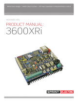
Figure 1-1 Overall view of the 470 series thyristor unitFigure 1-1 Overall view of the 470 series thyristor unit
Fail
Défaut
Adjust
Seuil
Test
I limit
Limit. I
Fuse fail
Déf. fusible
L
o
a
d
C
h
a
r
g
e
Diagnostic
socket
(Left)
Heatsink
EUROTHERM
240 V ~ 75 A
L
User terminal blocks
Power terminals
Control cable
clamp
P.Limit
P.Limit.
P.Adjust
P.Régl.
Diagnostic
socket
(Right)
Control cable
clamp

Identification Identification
470 User Manual
1-4
470 User Manual
1-4
The 470 series thyristor units are fitted with:
•a 'control board' which generates the input signals and controls the parameter measured
by the driver board;
•a 'driver board' which controls the true power of the load using the load voltage and
current measurements and retransmits the controlled parameter (DC voltage) and the
load voltage and current (instant AC values);
for the 472 model, this board generates the external thyristor firing signals;
• a 'neutral board' to connect the reference neutral or phase (depending on wiring);
• an 'RC snubber board' which protects the thyristors from fast voltage variations and
generates the thyristor firing pulses;
this board has a thyristor pulse gating circuit to prevent unstable firing in
certain applications.
The control system controls the true power, the squared voltage or the squared load current as a
function of an input signal and the selected feedback parameter.
The soft start (in thyristor firing angle variation) for high temperature coefficient resistive
loads and the delayed firing angle at the first half-cycle for the control of inductive and
transformer connected loads minimise transient over-currents.
The soft start (or end) duration can be set from 0 to 0.25 s per potentiometer located on the
control board.
The 470 series thyristor units are equipped with a power limit and, as an option, a current limit
(only available in Phase angle firing and Burst firing with soft start modes).
The partial load failure detection circuit (PLF) detects a 25 % increase in the load impedance
(independently of the power supply voltage variation).
The partial load failure detection circuit (PLF alarm) is set using a front panel potentiometer for
the real current of the load used. The PLF alarm is signalled by the alarm relay contact and by
the 'Load fail' indicator light on the front panel.

IdentificationIdentification
470 User Manual 1-5 470 User Manual 1-5
The 470 thyristor units have the following thyristor firing modes:
• thyristor firing angle variation ('Phase angle'),
• cyclic firing ratio modulation from 0 to 100 % ('Burst mode').
'Burst mode' firing is characterised by different modes:
• one firing or non-firing cycle ('Single cycle')
• slow cycle (modulation time 8 s at 50% setpoint)
• fast cycle (modulation time 0.8 s at 50% setpoint)
• burst firing (fast or slow) with soft start in thyristor firing angle variation
• burst firing (fast or slow) with soft start and end in thyristor firing angle variation.
The front panel comprises the following:
• the partial load failure detection setting potentiometer
• the 'Test' push button to test the partial load failure alarm setting
• the indicator light to display the partial load failure detection
• the current limit setting potentiometer (optional)
• the indicator to display an internal thyristor protection fuse blow-out
(470 and 471 models)
• the sockets (left and right) for diagnostics.
• the power limit setting potentiometer
• the calibration potentiometer
The 471 model thyristor units are equipped with a fan (100 A to 150 A nominal).
Thermal protection is provided by a thermal switch which detects if the fan has stopped or
the heatsink is overheated and inhibits thyristor unit firing.
The 470 thyristor unit is equipped with an active operation inhibit.
An external 10 V voltage (32 V max) or a contact connected to the control terminal block is
used to inhibit the thyristor unit.
The 470 series thyristor units can be plugged into the mounting backplate.

Identification Identification
470 User Manual
1-6
470 User Manual
1-6
TECHNICAL DATA
The 470 series power thyristor units are designed to control the true power of an industral
single-phase load with a high current requirement at start-up using thyristors.
!
Caution !
It is the user's responsibility to ensure that the thyristor unit nominal values are compatible
with the conditions of installation and operation before commissioning the thyristor unit.
Nominal current 15 A to 150 A (internal thyristors).
Up to 4000 A (external thyristor block)
Nominal line-to-line voltage 100 Vac to 500 Vac (+10%,-15%)
Inhibit below 70% of the nominal voltage;
return to 85 % of the nominal value
Power supply frequency 50 Hz or 60 Hz (±2 Hz)
Dissipated power 1.3 W (approximately) per ampere (470 and 471 models)
Cooling Permanent fan cooling above 100 A nominal
Fan Consumption 23 VA (471 model)
Powered by the auxiliary power supply voltage
Thyristor protection Internal high speed fuse (15 A to 125 A nominal)
External fuse for 150 A nominal (471 model)
Varistor and RC snubber circuit
Load Single-phase resistive with high temperature coefficient
or nductive or tranformer connected
Residual current In the OFF state,typically below 30 mA (internal thyristors)
External wiring To be performed according to the standards IEC 364
Mounting In closed metal cabinet
Operating temperature 0°C to +50°C in vertical position in altitude 2000 m maxi
Storage temperature -10°C to +70°C
Protection IP00 (can be opened without tools according to IEC 364)
Operating atmosphere Non-explosive, non-corrosive and non-conducting
Humidity RH of 5% to 95% without condensation
Pollution Degree 2 admissible, defined by IEC 664
Electromagnetic compatibility Immunity : comply with Standards EN 61000-4-2,
(the product installed and used EN 61000-4-4, EN 61000-4-3
in accordance with User Manual, Radiated emission : comply with EN 55011
see European Directives chapter) Conducted emission :
comply with EN 50081-2 (with an external filter),
comply with EN 61800-3 (without external filter).
Electrical safety Comply with Low Voltag Directive 73/23/EEC
CE Mark The 470 products are CE marked
(see European Directives chapter).
Power
Environment

IdentificationIdentification
470 User Manual 1-7 470 User Manual 1-7
Control
Control supply Connection of the auxiliary power supply to the user
terminal block.
Consumption: 7 VA (470 and 472 model) 30 VA (471 model)
Signal type Analogue
Setpoint Voltage: 0-5 V; 1-5 V or 0-10 V
Current: 0-5 mA ; 0-10 mA ; 0-20 mA or 4-20 mA
Input impedance Voltage: > 50 k
Ω
Current: 250 Ω or 1000 Ω (depending on configuration)
Manual control 10 kΩ external potentiometer
Thyristor firing modes The following can be reconfigured by the user:
• Phase angle
• Single cycle (burst firing with a firing or non-firing cycle)
• Fast cycle
(typical modulation time at 50 % power : 0.8 s)
• Slow cycle
(typical modulation time at 50 % power : 8 s)
• Fast cycle with adjustable soft start between
0 and 250 ms (with or without soft end)
• Slow cycle with adjustable soft start between
0 and 250 ms (with or without soft end)
Transient current
elimination Delayed firing of the 1st burst half-cycle (without soft operation)
for non-saturating inductive and transformer connected loads
Enable / Inhibit Using external contact or external voltage on the control
terminal block.
Response time: enable 2 s; inhibit < 20 ms
Diagnostics Two sockets for diagnostic unit used to set and control the
thyristor unit using test signals
Load control mode • True power
• Squared voltage
• Squared current
Wiring Shielded cable connected to ground at both ends.
Connection 0.5 mm
2
to 2.5 mm
2
wires
Tightening 0.7 N.m
The control terminals are isolated from the power and the
load circuit.

Identification Identification
470 User Manual
1-8
470 User Manual
1-8
!
Retransmissions
Signal outputs • Instant load current.
Rectified full wave signal (0 to 2.5 V mean)
proportional to the real load current image.
• True power (0 - 10 Vdc)
• Load current (0 - 2.5 Vac)
• Load voltage (0 - 2.5 Vac)
Threshold limit Maximum load current limit.
Setting using potentiometer on front panel.
Setting possible using an external potentiometer
or an external voltage.
Availability In 'Phase angle' and 'Burst firing with soft
start' modes.
Threshold limit Limit of controlled parameter by the control system
(true power, squared voltage or load current)
Setting using potentiometer on front panel.
Setting possible using an external potentiometer
or an external voltage.
Alarm 20% current decrease detection.
Setting on front panel using 'Adjust/Seuil' potentiometer.
Operation test Using 'Test' push button on front panel.
Signalling 'Load Fail' indicator light on the front panel.
Alarm relay contact open in alarm state (in standard version)
Contact closed in alarm state (optional)
Current limit (optional)
Partial load failure detection
Power limit
!
Caution !
Due to the continual improvement of products, Eurotherm may be required to
modify specifications without prior notice. For any further information and in
the event of doubt, contact your Eurotherm Office.
Retransmissions
Signal outputs • Instant load current.
Rectified full wave signal (0 to 2.5 V mean)
proportional to the real load current image.
• True power (0 - 10 Vdc)
• Load current (0 - 2.5 Vac)
• Load voltage (0 - 2.5 Vac)
Threshold limit Maximum load current limit.
Setting using potentiometer on front panel.
Setting possible using an external potentiometer
or an external voltage.
Availability In 'Phase angle' and 'Burst firing with soft
start' modes.
Threshold limit Limit of controlled parameter by the control system
(true power, squared voltage or load current)
Setting using potentiometer on front panel.
Setting possible using an external potentiometer
or an external voltage.
Alarm 20% current decrease detection.
Setting on front panel using 'Adjust/Seuil' potentiometer.
Operation test Using 'Test' push button on front panel.
Signalling 'Load Fail' indicator light on the front panel.
Alarm relay contact open in alarm state (in standard version)
Contact closed in alarm state (optional)
Current limit (optional)
Partial load failure detection
Caution !
Due to the continual improvement of products, Eurotherm may be required to
modify specifications without prior notice. For any further information and in
the event of doubt, contact your Eurotherm Office.
Power limit

IdentificationIdentification
470 User Manual 1-9 470 User Manual 1-9
Model / Nominal / Auxiliary power / Nominal / Input / Firing / Control / 0ptions / End
voltage supply current signal mode mode 00
THYRISTOR UNIT CODING
Model Code
Thyristor unit:
470 (75 A max) 470/113
471 (125 A max) 471/117
471 (150 A max) 471/100
Driver for external thyristors
472 472/000
Input signal Code
0-5 V 008
1-5 V 068
0-10 V 060
0-5 mA 069
0-10 mA 071
0-20 mA 072
4-20 mA 073
Thyristor firing Code
mode
Phase angle 002
Single cycle 160
Fast cycle (0.8 s) 001
Fast cycle
with soft start 055
Fast cycle
with soft start and end SDF
Slow cycle (8 s) 050
Slow cycle
with soft start 056
Slow cycle
with soft start and end SDS
Nominal voltage Code
100 V 26
110 V 10
115 V 51
120 V 24
200 V 27
220 V 12
230 V 52
240 V 13
277 V 32
380 V 22
400 V 53
415 V 23
440 V 28
480 V 15
500 V 29
Nominal current Code
470 model: 15 A 081
25 A 082
40 A 083
55 A 062
75 A 113
471 model: 100 A 114
125 A 117
150 A 100
472 model: external thyristors 000
Options Code
Current limit
(available in Phase angle
and soft start) 55
Frequency 60 Hz 69
PLF alarm contact
closed in alarm state 83
No backplate 76
Control mode Code
True power 28
Squared load voltage 26
Squared load current 29
Auxiliary power supply Code
100 V and 230 V 41
115 V and 230 V 19
200 V and 230 V 42
277 V and 230 V 46
380 V, 400 V, 415 V and 230 V 43
440 V and 230 V 47
480 V, 500 V and 230 V 44

Identification Identification
470 User Manual
1-10
470 User Manual
1-10
Backplate
Thyristor unit model / Nominal current / Backplate code / 00
For advance installation, order the mounting backplate without a unit.
Thyristor Nominal Backplate
unit model current code
470 15 A to 75 A LA 171569
471 100 A to 150 A LA 171570
472 External thyristors LA 171615
For deferred orders of units with no backplates (pre-installed backplates), use the thyristor unit
coding option 'No backplate' - code 76.
The full code for the 470 series thyristor units (shown on page 1-9 in 'Coding') specifies all the
technical characteristics selected by the client.
To simplify the process for ordering thyristor units, the 'short' code can be used, specifying the
model, the nominal current and the operating voltage.
The 'short' code is presented as follows.
Short or full code
Model / Nominal / Nominal / Auxiliary supply / 00
current voltage voltage
If the 'short' code is used, the 470 thyristor unit is supplied with the standard configuration:
• the input configured for 4-20 mA
• the thyristor firing mode: firing angle variation (Phase angle)
• frequency 50 Hz
• the delayed thyristor firing potentiometer is set for the 90° delay (inductive and
transformer connected load) and for the maximum start ramp (resistive load).

IdentificationIdentification
470 User Manual 1-11 470 User Manual 1-11
Caution !
!
Nominal load current 45 amperes
Nominal power supply voltage 380 volts line-to-line, 50 Hz
Auxiliary supply voltage 380 volts
Input signal 0 - 10 volts
Firing mode 'Fast cycle' burst mode firing
with soft start.
Control mode True power
Options: • Current limit
• 'Partial load failure detection' alarm relay
contact closed in alarm state
• No backplate.
470 / 113 / 22 / 43 / 062 / 060 / 055 / 28 / 55 / 83 / 76 / 00
CODING EXAMPLE
Thyristor unit coding
470 series thyristor unit and installation parameters
The nominal voltage of the 470 series thyristor unit must correspond
to the power supply voltage used to prevent problems of non-
operation for voltages lower than 70% of the nominal voltage
(inhibit below 70% of the nominal voltage, response time <10 ms;
automatic reset 2 s after return to 85 % of the nominal value).
To obtain optimum control, the nominal current of the thyristor unit
must be as close as possible (slightly above) the real load current.
Caution !
!
The nominal voltage of the 470 series thyristor unit must correspond
to the power supply voltage used to prevent problems of non-
operation for voltages lower than 70% of the nominal voltage
(inhibit below 70% of the nominal voltage, response time <10 ms;
automatic reset 2 s after return to 85 % of the nominal value).
To obtain optimum control, the nominal current of the thyristor unit
must be as close as possible (slightly above) the real load current.
/