Page is loading ...


IMPORTANT NOTICE!
Safety Definitions
This manual contains information that is very important to know and understand. This information is provided for
safety and to prevent equipment problems. To help recognize this information, observe the following symbols:
WARNING indicates a potentially hazardous situ-
ation which, if not avoided, could result in property
damage, serious personal injury or even death.
CAUTION indicates a potentially hazardous situation
which, if not avoided, may result in property damage,
or minor or moderate personal injury.
CAUTION
CAUTION used without the safety alert symbol in-
dicates a potentially hazardous situation which, if not
avoided, may result in property damage.
NOTE
Refers to important information and is placed in italic
type. It is recommended that you take special notice of
these items.
This manual has been prepared to acquaint you with the installation, operation, care and maintenance of your tow bar, and
to provide you with important safety information.
Read your owner’s manual cover to cover. Understand how to install and operate your tow bar, and carefully follow
the instructions and safety precautions.
Your tow bar has a one-year limited warranty. To qualify for your warranty, register online at www.roadmasterinc.com/
wreg, or fill out and return the enclosed product registration card. As a bonus, we’ll extend your warranty to a total
of two years at no additional cost, if we receive your registration (either online or mailed) within 30 days of pur-
chase.
We thank you for your patronage and greatly appreciate your discerning taste.
WELCOME TO THE ROADMASTER FAMILY!
Safety definitions .................................. inside front cover
Safe towing practices ..................................................1-2
Installer’s safety checklist ............................................2-3
Installing the ‘quick-disconnect’ system .......................3-4
Connecting and disconnecting
Connecting the tow bar ...........................................4-6
Disconnecting the tow bar .......................................... 6
Safety cables
How to use safety cables ...........................................7
Proper installation of safety cables ............................8
Care and cleaning ..........................................................9
Atwood coupler information ..........................................10
Limited warranty ........................................................... 11
Tow bar components ...................................... back cover
Your tow bar serial number…
…is on a metal label on the passenger’s side tow bar
arm. You will need this number when you fill out your
product registration card.
Write down the serial number in the space below and
retain for future reference.
Serial number:
Table of Contents
Read all instructions before installing
the tow bar, or before towing a vehicle.
Failure to understand how to properly in-
stall or operate the tow bar could result
in property damage, personal injury or
even death.
Save this manual
Save this manual for future reference. It contains impor-
tant sections relative to safety, use, maintenance, parts
replacement and other information. Therefore, make sure
this manual is always with you when you’re towing.
You may download or print a copy of the most current
manual at www.roadmasterinc.com (under ‘Support').
All illustrations and specifications contained herein are based on the latest
information available at the time of publication. ROADMASTER, Inc. reserves
the right to make changes, at any time, without notice, in material, specifica-
tions and models, or to discontinue models.

1
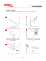
mounts, brackets, bolts, fasteners, wiring, the safety
cables and all other system components each time
before towing. Check
the coupler ball clamp
and ball socket (Fig-
ure 1) for fractures or
cracks in the steel.
If any component
is damaged, replace
it before towing.
Check the nut at
the bottom of the threaded hitch ball shank (Figure 2)
to ensure that it is
tightened to the man-
ufacturer’s torque
specifications. Inspect
the nut and the bot-
tom of the threaded
hitch ball shank (Fig-
ure 2) for signs of
wear caused when
the motorhome ‘bot-
toms out.’ If the nut is
damaged, replace it; if the threaded shank is damaged,
replace the hitch ball and shank.
Additionally, check the tow bar bracket every 3,000
miles — inspect for any fractures or cracks in the steel, or
any visible damage. Do not tow if the tow bar bracket is
damaged.
Additionally, check the torque on all bolts. (To find the
torque ratings, refer to the installation instructions for the
mounting bracket and the tow bar.)
• Never tow a vehicle with one of a comparable
weight. The towed vehicle’s weight should never exceed
40 percent of the towing vehicle’s weight.
Towing a vehicle with one of similar weight will cause
the towed vehicle to override the towing vehicle, result-
ing in “jackknifing,” “leapfrogging” or “fishtailing.” Serious
damage to both vehicles, as well as the towing system,
could result.
• Always stand to one side and as close to the motor-
home as possible when releasing the tow bar locking
mechanisms. Never stand between the adjustable arms,
or put any part of your body between the adjustable arms,
when releasing the tow bar — always stand to one side.
Because the towed vehicle may jerk forward when the
locking mechanisms are released, face the towed vehicle
and stand as close to the back of the motorhome as pos-
sible before releasing the locking mechanisms, to keep
from being hit by the towed vehicle.
• Check the motorhome turning radius. Some motor-
home chassis have such a tight turning radius that you
can damage your motorhome, towed vehicle or tow bar
while turning too sharply. Before getting on the road with
your towed vehicle, you should test your turning radius in
an empty parking lot.
With the towed vehicle attached, have someone watch
continued on next page
CAUTION
Do not back up the motorhome with the towed ve-
hicle attached.
Backing up with the towed vehicle attached will
cause the towed vehicle to “jackknife,” which will dam-
age the tow bar, the mounting bracket, the receiver
hitch, the towed vehicle's front end, and/or the rear
of the motorhome. Backing up with the towed vehicle
attached is the primary cause of tow bar damage and
will void the warranty.
• Be sure the vehicle can be towed before taking it on
the road. Some vehicles must be equipped with a transmis-
sion lube pump, an axle disconnect, driveline disconnect
or free-wheeling hubs before they can be towed. Failure
to properly equip the vehicle will cause severe damage
to the transmission.
Check the vehicle manufacturer’s instructions for the
proper procedure(s) to prepare the vehicle for towing.
• The tow bar must be approximately level with the
ball hitch on the motorhome. Towing with the tow bar
at an upward or downward slope puts undue strain on the
tow bar bracket and the ball mount. Driving over sharp in-
clines or declines could force the coupler off the hitch ball.
If it is necessary to raise or lower the hitch, two op-
tional accessories are available: an adjustable ball hitch,
part number 880; and roller hitch drops, in 4" through 10"
drops (part numbers 051-4 through 051-10).
• The steering wheel must be unlocked and free to
turn when towing. Failure to do so can cause severe
tire and equipment damage. Check the manufacturer’s
instructions for the proper towing procedure(s).
• Always use safety cables when towing. The safety
cables must connect the towed vehicle to the towing ve-
hicle, frame to frame.
Additionally, check to ensure that the safety cables are
the proper length. Refer to the sections titled “How to use
safety cables” and “Proper installation of safety cables”
for further information.
The weight capacity of the safety cables must meet
or exceed the towed weight, or the safety cables will
fail.
• The StowMaster All Terrain tow bar is rated at a maxi-
mum of 6,000 pounds carrying capacity; therefore the
weight of the towed vehicle and all its contents can-
not exceed 6,000 pounds. In addition, the hitch ball, the
receiver hitch, the safety cables and all supplementary
towing equipment must be rated at no less than the weight
of the towed vehicle and all its contents.
• The tow bar must be secured with linch pins (or op-
tional padlocks) before towing. Unless the tow bar is
secured to both vehicles with all appropriate pins (or pad-
locks), the towed vehicle will detach.
• This tow bar is designed for use on paved roads
only. ROADMASTER does not recommend off-road tow-
ing, nor does ROADMASTER warrant the tow bar for off-
road use.
• Inspect the system before towing — check the
SAFE TOWING PRACTICES
Figure 1
Figure 2

2
Safe towing practices
continued from preceding page
as you slowly turn sharply to see whether you have this
potential problem. If you do, note how far you can safely
turn the motorhome’s steering wheel, and be sure not
to turn it further when towing. Damage that results from
turning too sharply is not covered by warranty.
• Never use the tow bar to tow more than one vehicle.
In some states it is legal to have one vehicle towing more
than just one vehicle (for example, a truck which is towing
a trailer which is towing a boat). However, when using a
tow bar, never tow more than one vehicle, or non-warranty
damage or injury may result.
• The hitch ball must be two inches in diameter. If the
hitch ball diameter is smaller than two inches, the coupler
may disengage during towing.
Also, the diameter of the threaded hitch ball shank
(Figure 2) must match the diameter of the hole in the
ball mount hitch. If the threaded shank is too small, tow-
ing vibrations could cause the hitch ball to unthread and
separate from the ball mount hitch.
• Keep the tow bar clean and well-lubricated. As is
the case with most precision equipment, frequent cleaning
and care results in better performance and longevity.
Refer to the section titled “Care and cleaning” for further
information.
Failure to follow these instructions may cause prop-
erty damage, personal injury or even death.
INSTALLER'S SAFETY CHECKLIST
The following safety checklist is provided to the installer
with the instructions for installing the StowMaster All Ter-
rain tow bar. It is repeated here for your information.
As a precaution, verify that all safety requirements have
been followed before towing the vehicle.
• The installer must be sure that the vehicle is suit-
able or adaptable for towing. Some vehicles must be
equipped with a transmission lube pump, an axle discon-
nect, driveline disconnect or free-wheeling hubs before
they can be towed. Failure to properly equip the vehicle
will cause severe damage to the transmission.
Check the manufacturer’s instructions for the proper
procedure(s) to prepare the vehicle for towing.
• Read the instructions thoroughly before installing
the ‘quick-disconnect’ (‘QD’) system and its compo-
nents. The tow bar will be attached to the QD system.
If the QD system is not properly aligned, centered and
positioned on the towed vehicle, the tow bar will not be
centered on the towed vehicle, which may cause exces-
sive tire wear and other consequential, non-warranty dam-
age.
• Stress to the owner that the tow bar must be ap-
proximately level with the ball hitch on the motorhome.
Towing with the tow bar at an upward or downward slope
puts undue strain on the tow bar mounting bracket and the
ball mount. Driving over sharp inclines or declines could
force the coupler off the hitch ball.
• Show the owner how to properly operate the tow
bar. Familiarize yourself with the features of the tow bar.
Demonstrate them to the owner, and ask the owner to
connect and disconnect the tow bar and other components
of the towing system, until the owner is comfortable with
its operation.
• Advise the owner to always use safety cables when
towing. The safety cables must connect the towed vehicle
to the towing vehicle, frame to frame.
The weight capacity of the safety cables must meet
or exceed the towed weight, or the safety cables will
fail.
• The StowMaster All Terrain tow bar is rated at a maxi-
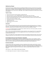
Figure 3
mum of 6,000 pounds carrying capacity; therefore the
weight of the towed vehicle and all its contents can-
not exceed 6,000 pounds. In addition, the hitch ball, the
receiver hitch, the safety cables and all supplementary
towing equipment must be rated at no less than the weight
of the towed vehicle and all its contents.
• Caution the owner to use a hitch ball with a two-
inch diameter. If the hitch ball diameter is smaller than
two inches, the coupler may disengage during towing.
In addition, the diameter of the threaded hitch ball
shank must match the diameter of the hole size in the ball
mount hitch. If the threaded hitch ball shank is too small,
towing vibrations could cause the hitch ball to unthread
and separate from the ball mount hitch.
• The tow bar must be attached to a bracket which is
bolted to the towed vehicle’s frame or unibody. In order
to be towed, virtually all vehicles require a tow bar mount-
ing bracket that is connected to the frame, unibody or
chassis and extends beyond the bumper.
• The tow bar must be mounted upright, with the cou-
pler facing out. See Figure 3. Never mount the tow bar
with the coupler facing any other way — the tow bar arms
and other components will be severely damaged during
towing.
• Caution the owner to secure the tow bar with linch
pins (or optional padlocks) before towing. Unless the
tow bar is secured to both vehicles with all appropriate
pins (or padlocks), the towed vehicle will detach.
• The installer must NOT use the tow bar as a ground
for welding. Connecting a ground to the ‘A-frame’ of the
tow bar will cause current to flow through the locking
continued on next page

3
Installer’s safety checklist
continued from preceding page
spring, which will detemper the spring and destroy the
locking mechanism.
• Under no circumstances should the tow bar be
welded to the vehicle, nor should any of the pre-punched
INSTALLING THE ‘QUICK-DISCONNECT’ SYSTEM
Figure 4
Quick-disconnect parts list:
(2) quick-disconnects
(parts “A” and “B”)
(2) safety plates (“C”)
All mounting hardware
This ROADMASTER tow bar is equipped with an exclu-
sive “quick-disconnect” (or, “QD”) system. Before connect-
ing the tow bar to the vehicle, first install the components
of the QD system to the mounting bracket.
Note: the quick-disconnect system is not used with
ROADMASTER ‘MS,’ ‘MX’ or ‘EZ5’ series mounting brack-
ets. If the towed vehicle has MS, MX or EZ5 brackets,
proceed to the next section — “Connecting the tow bar.”
The quick-disconnect system should be reserved, how-
ever, for subsequent vehicles which may not have these
brackets.
1. First, attach the quick-disconnects (“QDs,” parts “A”
and “B” in Figure 4) to the tow bar mounting brackets.
Attach the QDs so that the vertical pin on each is pointing
up, as shown in Figure 4.
Attach part “A” on the passenger side, and part “B”
on the driver side. Use the supplied ½" x 1¾" bolts, the
two safety plates (parts “C”), and the flat washers, lock
washers and nuts, as shown in Figure 4.
Note that both QDs have an extra hole — “D” in Figure
4 — for safety cable attachment. Mount parts “A” and “B”
so that the “D” holes are to the outside.
mounting holes be altered. Any welding or altering of the
tow bar will void the owner’s warranty.
Failure to follow these instructions may cause prop-
erty damage, personal injury or even death.
Figure 5
Do not tighten any of the bolts — leave them loose for
now — they will be tightened later.
Use all mounting hardware and both safety plates. If
all supplied materials are not used, the quick-discon-
nects or other components may vibrate loose, which
may cause property damage, personal injury or even
death.
2. Now, test-fit the crossbar — lower the crossbar (Figure
continued on next page

4
Towing vibrations will force the linch pins out un-
less they are properly locked in place over the verti-
cal pins on both quick-disconnects. Refer to Figure 6.
Failure to properly attach and lock both linch pins
will result in the loss of the towed vehicle, which may
cause property damage, personal injury or even death.
CONNECTING THE TOW BAR
Use caution when handling the tow bar — if your
hands, fingers or any part of your body are caught
between moving components, they can be pinched,
cut or otherwise injured.
1. Follow the preceding section in this manual — “Install-
ing the ‘quick-disconnect’ system” — to attach the tow bar
quick-disconnects (“QDs”) and the QD bases.
2. Drive the towed vehicle within three or three-and-a-half
feet of the motorhome hitch receiver. The vehicle does not
have to be perfectly centered to the hitch receiver, just
close.
Then, put the vehicle in gear (park), set the emergency
brake and chock one of the wheels.
3. With one hand, press down on the passenger side
release handle (the Freedom Latch™, Figure 7). With your
other hand, hold the
coupler and slide it
toward the passenger
side to disconnect the
tow bar from the stor-
age tab collar (Figure
8).
4. Swing the tow
bar up, in a counter-
clockwise direction
(Figure 9), until the bar is vertical. Then slide the driver's
side arm to the extreme right side of the stainless steel
slider bar (Figure 10).
Never release the tow bar arms when they are in the
vertical position. The arms can fall and cause severe
personal injury.
5. Lower the tow bar to position the coupler over the
continued on next page
Figure 7
Figure 8
Figure 6
Installing the ‘quick-disconnect’ system
continued from preceding page
5) over the quick-disconnects. The vertical pins at the top
of both QDs should fit through the top holes at the ends of
the crossbar (Figure 5), and the vertical pins at the bottom
of the crossbar should fit through the lower holes on the
quick-disconnects (Figure 5).
3. The quick-disconnects must be positioned so that the
tow bar is centered on the front of the vehicle.
If necessary, adjust the quick-disconnects by moving
them to the left or the right, until the tow bar is centered
to the front of the vehicle.
CAUTION
The quick-disconnects must be centered on the
mounting brackets. If they are attached too far to the
left or the right, the tow bar will not be centered on
the towed vehicle, which will cause excessive tire wear
and other consequential, non-warranty damage.
4. Once the crossbar slides on and off easily, torque the
four bolts to 75 ft./lbs.
Again, test-fit the crossbar over the QDs, to verify that
the crossbar slides on and off easily. If it does not, adjust
the QDs again.
5. Both linch pins must be inserted through the upper
holes in the vertical pins in parts “A” and “B,” as shown
in Figure 5.
Both linch pins must be locked. The rings (Figure 6)
are spring-loaded — they must be snapped over the pins,
as shown in Figure 6, with the curved side of the linch pins
touching the rings, in order to keep the QD bases secure.

5
Figure 9
Figure 10
Figure 11
Connecting the tow bar
continued from preceding page
hitch ball. Slide the tow bar arms forward or backward, as
needed, to maneuver the coupler over the hitch ball. If one
of the tow bar arms does not slide forward or backward,
lift the release handle (Figure 7) to unlock it.
6. With the coupler over the hitch ball, raise the coupler
locking lever (Figure 11) until the tab ‘ear’ (Figure 11)
just clears the tab hole (Figure 11), and pull straight back
toward the towed vehicle.
Now, lower the coupler over the hitch ball so that it
completely covers it, and slide the coupler locking lever
(Figure 11) forward until it locks on the ball.
Note: an optional coupler lock (part number 305) is
available for added protection against accidental coupler
disconnect.
Be certain the coupler is properly locked onto the hitch
ball. The tab ear will slide back into the tab hole when the
mechanism is fully engaged.
If the coupler is not properly locked onto the hitch
ball, as described above, it will release during towing.
Swing the
tow bar up,
in a counter-
clockwise
direction.
coupler
driver's side
arm
stainless
steel
slider bar
Slide the driver's
side arm to the
extreme right
side of the
stainless steel
slider bar.
The tow bar will separate from the motorhome, which
may cause property damage, personal injury or even
death.
7. Attach the safety cables (See “How to use safety
cables” and “Proper installation of safety cables.”) and
plug in the electrical wiring cord, according to the sup-
plier’s instructions.
Before towing the vehicle, make sure the steering is
unlocked, the transmission is in the proper setting and the
emergency brake is released. Remove the wheel chock.
Check the manufacturer’s specifications, the owner’s
manual, or talk to the installer for the proper towing pro-
cedures or requirement(s) for the vehicle to be towed.
Do not tow the vehicle until the tow bar is properly
attached with all pins or padlocks. Unless the tow bar
is secured to both vehicles with all appropriate pins
or padlocks, the vehicle will detach, which may cause
property damage, personal injury or even death.
When you drive away, steer briefly to the left and then
to the right, to extend, self-center and lock the tow bar.
Always stop at this time. Check the tow bar to ensure
that both arms are locked before assuming highway speed.
Additionally, check the other components of your towing
system, to ensure that they are fully engaged.
Both tow bar arms must be locked before towing. If
they are not, the momentum of the towed vehicle will
apply excessive force to the tow bar arms and other
components of the towing system, which may cause
the towing system to fail, resulting in property dam-
age, personal injury or even death.
If the motorhome hitch receiver has an extension,
continued on next page

6
DISCONNECTING THE TOW BAR
Allow the towed vehicle to idle forward just enough to
take the tension of this weight off the coupler. Then hold
the vehicle in position by first applying the emergency-
brake, then shifting into park.
Once the tension is off, pull back on the coupler locking
lever to release the coupler.
5. Lift the coupler up, until the tow bar is completely
vertical. Lift up on the release handle on the driver’s side
arm, and allow the arm to compress.
Slide the driver’s side arm to the extreme left side of
the stainless steel slider bar. Lower the coupler down until
the coupler rests on the driver’s side.
6. To secure the tow bar on the towed vehicle, lift the
release handle (Figure 7) on the passenger side arm and
move the coupler to
the right, until the
storage tab lock (Fig-
ure 8) slides through
the storage tab collar
(Figure 8), as shown
in Figure 13.
7. To remove the tow bar, remove the two linch pins (Fig-
ures 5 and 6) at the top of both quick-disconnects, and
lift the tow bar up and away.
(ROADMASTER recommends replacing at least one
linch pin with a padlock — part number 301 or 302 — to
prevent accidental release or theft.)
Unless the storage tab lock is in place (as shown in
Figure 13) before the tow bar is removed, the base of
the tow bar may fall, which may cause severe personal
injury.
Figure 13
Connecting the tow bar
continued from preceding page
do not tow if the tow bar is more than three inches out
of level.
Receiver extensions cause the towing system to
swing much higher and lower than towing systems
without extensions. This enlarged arc of motion cre-
ates excessive strain on the tow bar, brackets and
frame, which can cause the towing system to fail, caus-
ing property damage, personal injury or even death.
Do not tow a vehicle using tow bar mounting brack-
ets, safety cables, or a hitch receiver rated less than
the actual weight of the towed vehicle.
If the brackets, safety cables, hitch receiver or any
supplementary towing equipment is not rated at the
weight of the towed vehicle and all its contents, it
may fail during towing, causing property damage, per-
sonal injury or even death.
1. Disconnecting the tow bar is essentially the reverse
of connecting it. First, always try to park on level ground,
with the towed vehicle in line with the motorhome. This
will eliminate most of the tension between the vehicles,
allowing for an easier disconnect.
2. Disconnect the electrical wiring harness, safety cables,
and any other towing system accessories.
3. Put the towed vehicle in gear (park), set the emergency
brake and chock one of the wheels.
Always put the towed vehicle in gear (park), set the
emergency brake and chock one of the wheels before
lifting the coupler off the hitch ball.
Failure to do so may result in a ‘runaway’ vehicle
or may crush you between the towed vehicle and the
motorhome, causing property damage, personal injury
or even death.
4. Pull back on the coupler locking lever (Figure 11) to
release the coupler, and lift the coupler off the ball.
Note: if it is difficult to lift the coupler, the towed ve-
hicle’s weight may be pressing against it. Release the
pressure by pushing down on one or both of the release
handles (the Freedom Latches™, Figure 7) to unlock them.
Note: if you must park on an uphill incline, you may
find that you cannot release the coupler even with the tow
bar arms released. The weight of the towed vehicle trying
to roll back (Figure 12) is binding the coupler in place.
Figure 12

HOW TO USE SAFETY CABLES
Safety cables are an integral part of your towing system.
They are a secondary safety device, required by law in
many states. This section, and the following section, will
acquaint you with how to use them properly.
• The safety cables must be rated at 6,000 pounds
weight capacity (the maximum capacity of the StowMas-
ter All-Terrain tow bar). The weight of the towed vehicle
and all its contents cannot exceed 6,000 pounds.
• The safety cables must connect the towing vehicle to
the towed vehicle, frame to frame.
• Pull the safety cables so that all the slack is at the
motorhome. Make sure there is enough slack in the
cables at the motorhome to allow for sharp turns — if
there is not enough slack, the towing system will be se-
verely damaged when the motorhome turns.
• The safety cables must be the correct length…
• Make sure the cables are not too short — if you use
a receiver hitch extension or other equipment that ex-
tends the distance between the towed vehicle and the
motorhome, the standard cables may be too short. If the
cables are too short, the towing system will be severely
damaged when the motorhome turns a sharp corner.
(Safety cable extensions in a variety of lengths are
available from ROADMASTER.)
• Make sure the cables are not too long — the cables
should not hang down to the extent they may catch on
obstructions, or drag on the ground. This much slack could
cause damage to the towing system, the towed vehicle or
the motorhome. If the cables are too long, wrap the excess
cable around the tow bar to take up the slack. Make sure
there is enough slack in the cables at the motorhome
to allow for sharp turns.
Damage caused by using safety cables of an incorrect
length is not covered under warranty.
• Always cross the cables under the hitch receiver, as
shown in Figure 14 under “Proper installation of safety
cables.” In the unlikely event the tow bar separates from
the motorhome, crossing the cables will help prevent the
tow bar from dragging on the ground, which can cause
the tow bar to “pole vault” the towed vehicle.
• Some ROADMASTER tow bar mounting kits with re-
movable arms use two safety cables on each side. If two
sets of safety cables are required, both must be used. This
is required by law. Refer to “Proper installation of safety
cables” for further information.
Failure to follow these instructions may cause prop-
erty damage, personal injury or even death.
7

PROPER INSTALLATION OF SAFETY CABLES
For all towing systems…
Use the built-in cable guides and cross the safety ca-
bles under the hitch receiver, as shown in Figure 14.
Unscrew the connecting nuts on each quick link to
connect the safety cable loops. Finger-tighten the nuts
firmly, until the loop is completely closed, to secure the
attachment. Do not substitute carabiners or other devices
for the quick links — the quick links are designed to hold
the weight of a towed vehicle; carabiners or other devices
are not.
Option 1
If the tow bar mounting bracket is similar to the one
shown in Figure 14 and the safety cables are long enough,
connect the snap hook (or quick link) to the safety cable
anchor built into the mounting bracket.
Note: the snap hooks can be attached at either the
towed vehicle or the motorhome.
Option 2
Some ROADMASTER tow bar mounting brackets with
removable arms, such as the one in Figure 15, use both
a long safety cable and a short safety cable on each side.
Each long safety cable runs from the towing vehicle to
a quick link attaching it to one of the quick-disconnects.
This quick link is also an attachment point for one of the
short safety cables; another quick link attaches the short
safety cable to the mounting bracket.
The safety cables must be carefully routed so that
they cannot become pinched, frayed, scraped or oth-
erwise damaged, and so they will not drag when go-
ing over dips or low spots. Do not use the cables if
they show any signs of wear or damage — immediately
discontinue towing and replace the cables.
Failure to follow these instructions will result in
cable failure, which may cause property damage, per-
Figure 14
Figure 15
Option 2
Option 1
(Safety cable anchor is not present on all brackets.)
sonal injury or even death.
If the quick links are not completely tightened, with
the loop closed, the safety cables may detach. In the
event of a towing system failure, the towed vehicle will
detach, which may cause property damage, personal
injury or even death.
If your towing system requires two sets of safety
cables, always use both the long and the short safety
cables. Connect them as shown in Figure 15. Oth-
erwise, in the event of a towing system failure, the
towed vehicle will detach, which may cause property
damage, personal injury or even death.
8

CARE AND CLEANING
Clean the interior of the coupler, and wipe away the old
grease, dirt and debris.
After cleaning the tow bar, wipe any remaining cleaner
away.
Now that you have a clean, dry tow bar, use a dry sili-
cone aerosol, such as LubeMaster (part number 747), to
lubricate the tow bar — spray a liberal amount of silicone
into all moving components, including the driver’s side
collar.
Flex the tow bar components to work the lubricant in.
To lubricate the locking mechanisms, first clean the
moving parts with a water-soluble cleaner, wipe away the
excess until the mechanisms are clean and dry, then spray
silicone lubricant inside (Figure 17). After the lubricant has
dried, move the release handles up and down to work the
lubricant in.
CAUTION
Always clean the locking mechanisms, as described
above, before lubricating them. Silicone coats and cov-
ers in a thin layer. If it is not removed, it will reduce
the clearance for the locking mechanisms, preventing
proper operation.
Lubricate the coupler ball socket and ball clamp (Figure
1) with wheel bearing grease; lubricate all other moving
components of the coupler with SAE 30 weight oil. (See
“Atwood coupler information.”)
Extended storage — before storing your tow bar for an
extended period of time, clean and lubricate it as directed
above. Store the tow bar in its cover (optional, part number
052-2), to protect it from the elements.
Note: to remove scratches and restore luster on the
inner arms, we suggest you use extra fine (0000) steel
wool, 3M “Scotch Brite” (fine pad) or a similar product.
Figure 16
Figure 17
As is the case with most precision equipment, frequent
cleaning and care results in better performance and lon-
gevity. Use the following guidelines to keep your tow bar
clean and well-lubricated.
Always clean the tow bar before lubricating. Use a wa-
ter-soluble cleaner such as Voom RV (part number 9911)
— it does an exceptional job of breaking down road film,
dirt and grease.
CAUTION
Do not use petroleum-based products to clean or lu-
bricate the tow bar. Petroleum will attract dirt and dust,
which will impede the operation of the sliding arms
and/or other components. Certain petroleum products
may also corrode non-metallic components.
Damage caused by using a petroleum-based prod-
uct to clean or lubricate the tow bar is not covered
under warranty.
Clean all moving components, paying special attention
to the inner arms and the slider bar — with both tow bar
arms lowered and extended, spray a liberal amount of
cleaner on the inner arms and the end of each outer arm
(Figure 16).
Raise the tow bar, until it is horizontal to the ground.
Raise each release handle up, and retract and extend
each tow bar arm several times. As the arm closes, the
cleaner will lift dirt and debris from the interior of the outer
arm. Wipe the dirt and debris off and repeat, if necessary,
until each arm is clean.
Next, with both tow bar arms horizontal to the ground,
spray cleaner across the stainless steel slider bar (Figure
16) and into the collar on the driver’s side arm. Then slide
the driver’s side arm back and forth, across the slider bar.
The cleaner will lift dirt and debris off the slider bar and
collar. Wipe the dirt and debris off and repeat, if necessary,
until the slider bar and collar are clean.
9

ATWOOD COUPLER INFORMATION
Following are the operation, latching and maintenance
instructions from the coupler manufacturer, repeated here
for your information. (References to trailer use do not ap-
ply to the StowMaster All-Terrain tow bar.)
Operation
Warning — Personal Injury
• Safe towing practice requires the proper use of
safety chains used in accordance with instructions
provided by the trailer manufacturer.
• Check that the ball has been completely inserted
into the coupler ball socket and the ball clamp (inside
the coupler) is closed around the underside of the tow
ball and the handle is in the closed position.
• The loaded weight of the trailer must never exceed
the least capacity marked on the coupler, tow ball,
hitch, trailer or vehicle.
• Check coupler, hitch and ball for damage or wear
before each use. Assure all parts operate freely. Re-
place any component if worn or damaged.
• Failure to follow warnings and instructions could
result in separation of tow vehicle and trailer which
can result in death, personal injury and property dam-
age.
Warning — Personal Injury
• For proper tow vehicle and trailer hookup, towing
performance and to prevent damage to hitch and trailer
coupling, the tow vehicle and trailer are to be level
with respect to flat ground after hitching up. If your
trailer is not level, equipment is available to raise or
lower the hitch ball.
Caution — Product Damage
• Use caution when backing or towing vehicle for
hook-up, damage to coupler may result.
• Avoid sharp turns when towing or backing. Jack-
knifing could bend coupler or create extreme stress
or fracture.
Latching Instructions — Yoke Style Couplers
Warning — Personal Injury
• Always open latch handle before inserting ball.
1. To open, lift the latch handle and pull backward, raising
the yoke and resting it on the nose of the coupler (Fig
9-A).
2. Place coupler on ball of same diameter as coupler and
of same or greater capacity.
3. When ball is completely nested in ball socket, push latch
handle forward until yoke drops over nose of coupler and
the latch handle locking tips freely enter slots on top of
coupler (Fig 9-B).
4. Extend jack to ground and lift car/trailer combination
2" - 4" to insure coupler is securely attached to tow ball.
Retract jack completely before towing.
5. Insert padlock or bolt through lock hole in yoke for theft
protection.
Note: these couplers are not adjustable for ball size.
Maintenance
1. Lubricate ball socket and ball clamp with wheel bearing
grease. Clean and lubricate monthly.
2. Check towing hitch, ball and coupler for signs of wear
before each trip. Replace coupler if damaged or worn.
3. Lubricate moving or sliding parts monthly with SAE 30
weight oil.
9
-A
9
-B
10

LIMITED WARRANTY
1. WARRANTY
1a. WARRANTY OF CONFORMITY AT TIME OF SALE
ROADMASTER, Inc. warrants that at the time of sale
of this product it will be free from defects in material and
manufacture and will conform to ROADMASTER’S speci-
fications for the product.
1b. CONDITIONAL ONE-YEAR WARRANTY
In addition to the preceding time-of-sale warranty, if the
product registration card is completely and accurately filled
out and mailed to ROADMASTER within thirty (30) days
of purchase, ROADMASTER will provide an additional
warranty that for a period of one year after sale the prod-
uct will remain in good working order, PROVIDED THAT
the product is installed and maintained in accordance
with ROADMASTER’S instructions and is not subjected
to: (a) alteration or unauthorized repairs or repairs by
anyone other than ROADMASTER or a ROADMASTER-
authorized service center, (b) misuse, abuse, commercial
use, or improper maintenance, (c) Acts of God (including
without limitation hurricanes, tornadoes, floods, or other
severe weather or natural phenomena), (d) failures due
to products not supplied by ROADMASTER, or (e) other
treatments, uses, or installations for which the product was
not intended. This warranty extends only to the first retail
purchaser-consumer of the product and is not transferable.
EXTENDED WARRANTY PERIOD: If ROADMASTER
receives the product registration card, completely and
accurately filled out, within thirty (30) days of purchase,
ROADMASTER will enlarge the one-year warranty period
in the preceding paragraph to a period of two years.
2. DISCLAIMER OF OTHER WARRANTIES
The preceding warranties are the exclusive and sole
express warranties given by ROADMASTER. They su-
persede any prior, contrary or additional representations,
whether oral or written. No agent, representative, dealer
or employee has the authority to alter or increase the obli-
gations or limitations of this warranty. Any implied warran-
ties, including the WARRANTY OF MERCHANTABILITY
and any WARRANTY OF FITNESS FOR A PARTICULAR
PURPOSE, are limited in duration to thirty days or the
term of the applicable express warranty provided above,
whichever is longer.
Some states do not allow limitations on how long an
implied warranty lasts, so the above limitation may not
apply to you.
3. EXCLUSIVE REMEDY FOR ANY NONCONFORMITIES
If during the applicable Warranty Period, the product
does not conform to the preceding Warranties, notify
ROADMASTER as provided below, and within a reason-
able time ROADMASTER will provide, at its option, one of
the following: (1) replacement components for any non-
conforming or defective product or components or (2) the
percentage of the purchase price for the nonconforming
product equal to the percentage of the Warranty Period
remaining when ROADMASTER is notified of the noncon-
formity. ROADMASTER will, at its option, (a) use new and/
or reconditioned parts in performing warranty repairs and
making replacement products, (b) use parts or products of
original or improved design in the repair or replacement. If
ROADMASTER repairs or replaces a product, its warranty
continues for the remaining portion of the original War-
ranty Period or 60 days from the date of the return ship-
ment to the customer, whichever is greater. All replaced
products and all parts removed from repaired products
become the property of ROADMASTER. ROADMASTER
will not provide, and will not be liable for, labor, costs of
removal or reinstallation of components, disposal, ship-
ping, freight, taxes, or other incidental charges.
THESE REMEDIES ARE THE EXCLUSIVE AND SOLE
REMEDIES FOR ANY BREACH OF WARRANTY.
For any breach of warranty, the Owner must telephone
ROADMASTER at 1-800-669-9690 within thirty (30) days
after discovering the nonconformity. Do not return any
product without first calling ROADMASTER and getting
a return authorization number. Returned products must
include the return authorization number and a copy of the
original invoice, bill or other proof of the date of purchase.
The date of purchase must coincide with the original war-
ranty registration card on file. ROADMASTER will au-
thorize (a) shipment of the product to ROADMASTER or
(b) repair or replacement at the nearest warranty service
center—in both cases with shipping at your expense. Do
not purchase replacement parts or pay for repair labor—you
will not be reimbursed. Compliance with the requirements
of this paragraph is a condition to coverage under the
Warranty: if these requirements are not complied with,
ROADMASTER will have no obligation to provide any rem-
edy for any breach of warranty.
4. DISCLAIMER OF INCIDENTAL AND CONSEQUENTIAL
DAMAGES
IN NO EVENT SHALL ROADMASTER BE LIABLE FOR
ANY INCIDENTAL, SPECIAL, INDIRECT OR CONSE-
QUENTIAL DAMAGES, WHETHER RESULTING FROM
NONDELIVERY OR FROM THE USE, MISUSE OR IN-
ABILITY TO USE THE PRODUCT OR FROM DEFECTS
IN THE PRODUCT.
Some states do not allow the exclusion or limitation of
incidental or consequential damages, so the above limita-
tion may not apply to you.
5. APPLICABLE LAW
This Warranty will be interpreted, construed, and en-
forced in all respects in accordance with the laws of the
State of Washington, without reference to its choice of law
rules. The U.N. Convention on Contracts for the Interna-
tional Sale of Goods will not apply to this Warranty.
6. SEVERABILITY
If any provision of this warranty is found to be invalid or
unenforceable, then the remainder shall have full force and
effect, and the invalid provision shall be partially enforced
to the maximum extent permitted by law to effectuate the
purpose of the agreement.
7. ADDRESS FOR NOTICES TO ROADMASTER
ROADMASTER, Inc., 6110 NE 127th Ave, Vancouver,
WA 98682
This warranty gives you specific legal rights, and you
may also have other rights which vary from State to State.
11

STOWMASTER ALL TERRAIN COMPONENTS
part
description number
1 quick-disconnects, car
side set (color-coded red) ............................... 222
1a linch pins (two) .............................. 357000-00
1b quick-disconnect bolt kit ................ 910005-00
1c quick-disconnect
backing plate (one).............................. 222-20
2 quick-disconnect/slider bar assembly
(color-coded black) .................................... 910080
2a 3/8" x ½" square head screw
(two) .............................................. 350456-00
2b long tow bar collar (one) .................C-000790
2c ½" x ¼" x 2" plate washer (two) ... 350354-00
2d ½" x 1½" bolt (two) ....................... 350095-10
2e base tube (one) — includes four
½" x 1½" bolts and eight ½" lock
washers ...........................................C-000800
2f 3/8" nylon lock nut (three) ............. 350255-00
2g short tow bar collar (one) ................C-000791
2h ½" x 2" socket shoulder
bolt (three) ..................................... 350376-00
3 ½" nylon washer
(four; color-coded green) ...................... 350356-00
4 pivot nut (two; color-coded green) ........ 650004-80
5 inner and outer arm assembly, passenger side
(color-coded black) ............................... 910021-62
part
description number
5a inner arm assembly, passenger side
(one) — includes anvil, compression
spring and 3/8" x 2¾" bolt ............. 910021-64
5b nylatron bushing (two) ................... 200029-70
5c 1½" outer arm cap (two) ............... 200140-00
6 All Terrain handle repair kit
(two sets; color-coded red — includes two lock
lever pins, two lever springs, two E-clips and
two handles) ......................................... 910003-05
7 inner and outer arm assembly, driver's side
(color-coded black) ............................... 910021-61
7a inner arm assembly, driver's side
(one) — includes anvil, compression
spring and 3/8" x 2¾" bolt ............. 910021-63
8 yoke and coupler assembly
(one; color-coded red) ............................C-000802
8a ½" x 3" socket shoulder
bolt (two) ....................................... 350101-00
8b ½" nylon lock nut (two) ................. 350259-00
Please have your serial number
handy when calling for repair parts,
as not all versions of this tow bar
use the same parts.
/