Page is loading ...

Martin TrackPod 2.0 Page 1
MARTIN TRACKPOD
2.0BETA
Getting Started
Fifth Edition: November 2001
MARTIN TRACKPOD
2.0BETA

Page 2 Getting Started
Martin TrackPod, by Acoustic Positioning Research Incorporated,
Edmonton, Canada. Protected by international patents pending PCT/
CA98/00684.
Lighting control portions of the TrackPod software are licensed exclu-
sively world-wide to Martin Professional A/S, Denmark by APR inc.
Virtual positioning control technology is licensed non-exclusively to
Martin Professional A/S by APR.
Martin TrackPod is a trademark of Martin Professional A/S. Other
product names mentioned may be trademarks or registered trademarks
of other companies.
The information in this booklet is furnished for informational use only,
is subject to change without notice, and should not be construed as a
commitment by Martin Professional A/S or APR inc. Martin Profes-
sional and APR assume no responsibility or liability for any errors or
inaccuracies that may appear in this manual.
No part of this manual may be reproduced, in any form or by any
means, without prior written approval of Martin Professional A/S.
© Martin Professional A/S, Denmark. All Rights Reserved.
Printed in Canada
Fifth Edition: November 2001.
Martin Professional A/S APR inc.
Olof Palme Allé 18 Suite 200, 8526-109 St.
8200 Aarhus, Denmark Edmonton, Alberta
www.martin.dk T6G 1E5 Canada

Martin TrackPod 2.0 Page 3
Contents
General warnings 4
Laser information 4
Laser safety 5
Welcome 6
What’s included in the TrackPod package 6
What’s NOT included in the package 6
Software installation 6
TrackPod card installation 7
TrackPod assembly 8
TrackPod connections 9
TrackPod placement 9
TrackPod controller 11
Before you begin 12
TrackPod calibration 13
Automatic calibration 13
Manual calibration 15
After TrackPod calibration 16
How to connect to DMX consoles and fixtures 17
Basic light definition 18
Groups 18
Followspot calibration 18
Automatic followspot calibration 19
Manual calibration 21
Followspot set-up recommendations 22
A tour of the TrackPod software 23
Map editor - programming 23
Quickmap vs layers 24
Assigning behaviour 24
Fader patch 25
Height control 26
Megapod 28
More on maps 28
Map remote control 28
Using the new console driver 29
Real time - playback 30
Real time screen 30
The controller’s features 31
Example 32
About sighting devices 32
For further reference 33

Page 4 Getting Started
General warnings
1. The TrackPod is not for domestic use.
2. Use the device only as described in this manual.
3. Do not expose it to rain or moisture.
4. The TrackPod controller does not have an ON/OFF switch. It turns
ON automatically when it is connected to the mains. Therefore, before
connecting, please make sure to switch the TrackPod controller’s
power to 115 or 230V according to your needs.
5. Make sure the device is properly grounded.
6. Immediately repair or replace damaged power cords.
7. There are no user-serviceable parts inside; refer all service to a
qualified technician.
Laser information
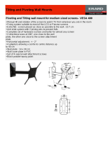
The TrackPod contains a class 3A laser calibrator with a 5mW maxi-
mum power output. It is located below and protruding from the Track-
Pod’s general-purpose attachment plate, between the two counter-
weights and within a grounded enclosure (see Figure 1 in the next page).
The only aperture through which laser light is emitted is directly in the
centre of the grounded enclosure, with the beam being colinear with the
attachment plate.
The laser produces an intense, highly directional beam of light. It is
needed only briefly during the TrackPod calibration procedures and
cannot be turned on during normal operation. The TrackPod’s laser will
only turn ON when all the following conditions are met:
1. The TrackPod is powered on.
2. The laser is connected to the TrackPod controller.
3. The TrackPod is connected to the control PC.
4. The TrackPod software is running in the control PC.
5. The TrackPod is in the automatic calibration mode. Tip: you may
block access to this mode to prevent unauthorized operators from
calibrating the instrument. Set the appropriate access priviledges in
the preferences screen of the TrackPod software.
6. The laser aperture is not blocked by a lid or cap.
7. The F3 button in the TrackPod controller is pressed. Releasing the F3
button stops laser emission.

Martin TrackPod 2.0 Page 5
Laser safety
1. DO NOT STARE INTO THE BEAM OR VIEW DIRECTLY WITH
OPTICAL INSTRUMENTS. Extended direct exposure can result in
damage to the eyes.
2. The laser should never be used while other people are walking around
the stage, unless they are wearing protective goggles.
3. Avoid pointing the laser at mirrors or reflective surfaces.
4. Only qualified and trained employees approved by a laser safety
officer should be assigned to install, adjust and calibrate the TrackPod.
5. When not in use, the TrackPod should be stored safely out of reach of
unauthorized personnel.
6. Do not remove the warning label on the TrackPod’s general purpose
attachment plate.
7. Consult local and state laws regarding laser use and possible registra-
tion requirements.
8. Do not open the laser enclosure under any circumstances.
Laser aperture
General purpose
attachment plate
TrackPod
Controller
Laser
warning
label
Counterweight
F3 button
FIGURE 1

Page 6 Getting Started
Welcome!
Thank you for purchasing the Martin TrackPod, the World’s most
sophisticated automated followspot tracking system. This booklet
contains introductory information on how to set up and use your system.
To get the most out of the TrackPod, like with any other sophisticated
controller, the lighting designer or technician will need to familiarise
him or herself with the system. You may want to receive training from
your Martin dealer in order to learn the TrackPod thoroughly. In addi-
tion, please read this booklet in its entirety and look over the rollover
tips and informative memos that appear in the TrackPod software.
What’s included with the
TrackPod package?
1 CD-ROM with software and utilities
1 Getting Started booklet
1 TrackPod ISA card with TrackPod and DMX connectors
1 TrackPod controller with switchable power supply and cables
1 sensor head with laser calibrator
4 Laser reflectors for calibration
1 Tripod
1 Flight case
What’s NOT included with the
TrackPod package?
A PC compatible computer
DMX cables
A sighting device such as a video camera, telrad or scope.
A TrackPod PC card for portable computers (sold separately)
Additional DMX cards to increase the channels from 512 to up to 3584
Software installation
The TrackPod software is supplied in a CD-ROM. Insert the CD-ROM
and double-click on the “Setup” icon. This will run a wizard that will
help you install the software.

Martin TrackPod 2.0 Page 7
You may also download the most recent software from the Martin
website www.martin.dk. This may be useful if you do not have a CD-
ROM reader in your TrackPod PC as you may download the software in
a zipped format that can fit into a few 3.5” diskettes. You may use the
software without installing the TrackPod hardware.
The minimum PC requirements to run the software are:
Operating System: Windows 95, 98, ME, NT, 2000 or XP
Processor: Pentium III 500
RAM: 32 MB RAM
Hard disk: 10 MB disk space
Display: 800 x 600 pixels, 16-bit (high colour)
Mouse: 2-button mouse
Expansion Slot: one 8-bit ISA slot.
PCMCIA Slot: for optional laptop compatibility
Video card: nVidia GeForce 2 or 3 recommended
TrackPod card installation
The TrackPod card is an 8-bit ISA card that needs to be inserted into
your PC. Make sure the PC is turned off and its power cord is unplugged
from the wall. Remove the PC chassis cover as discussed in your PC
owner’s manual. Locate an ISA bus card slot and insert the TrackPod
card in it, making sure that the card is nestled all the way into the slot.
Secure the card by screwing the card’s bracket to the computer chassis.
Please note: the TrackPod card is very sensitive to electrostatic charges.
When it is not in the PC, keep the card in the anti-static bag provided.
The TrackPod card is a memory mapped I/O device with a default
memory setting of $D0000. To verify that this memory is free in your
PC do the following:
Right-click on “My Computer” icon
On the pop-up menu that appears, select “Properties”
Select the “Device Manager” tab
Click on the “Properties” button
Click on the “Memory” radio button
This will open a window that details the memory assignments for the
installed hardware. The default address of the TrackPod ISA card is
$D0000 - D0FFF. If this is not free, check which memory space is

Page 8 Getting Started
available and use the card’s dip switches to set that address. Since the
TrackPod card is based on Martin’s 4064 card you can obtain detailed
instructions on setting the address at
http://www.martin.dk/service/manuals/4064inst.pdf
Please note that in the great majority of cases the default address is fine.
If you are aware that other hardware in the PC is using the TrackPod
default address, or if you are experiencing unexpected system crashes,
then perform this procedure.
Tip: Shadowing should be disabled for the TrackPod card’s memory
address. This is done by visiting your PC’s BIOS, typically under the
heading “BIOS Features Setup”.
TrackPod assembly
Figures 1 and 2 show the parts of the TrackPod. Unfold the tripod as
widely as possible and set it to a comfortable height. Screw the Track-
Pod head on the tripod until it is fully inserted in the thread. Make sure
to lock the head using the pan lock knob; the idea is that the pan move-
ment will take place at the pan encoder not the tripod thread. Attach the
handle bars by inserting them in the clamp grips on the sides of the
TrackPod head plate. The grips for the handle bars are saw-toothed so
that you may choose an appropriate angle between the TrackPod
attachment plate and the handles. Since TrackPods are located above the
stage, the operator will be pointing it down most of the time and there-
fore a sharp angle of 90-120 degrees is preferred. Lock the handles in
place, making sure that the handles protrude from the head at an angle
of about 30 degrees between them, as shown in Figure 2.
Place the controller on the handle bars so that the two handle bars are
outside the thumb screws, i.e. the handle bars should NOT go between
the screws and the controller box. You will have to find the right height
at which this is possible and perhaps even adjust the angle at which the
handles diverge. Secure the controller in place by using the thumb
screw, the bracket holder and the butterfly nut. Extend the handle bars to
a comfortable length and lock them in place.
Mount and lock the counterweights underneath the front end of the
attachment plate, beside the laser. Slide the weights along the bars until
the TrackPod is balanced. Ensure that the weights are firmly attached
and that a safety lock is placed at the end of the rods.

Martin TrackPod 2.0 Page 9
TrackPod connections
The back of the controller box has several connectors. The laser and the
pan and tilt encoders come with attached cables which must be plugged
into the appropriate connectors. The male XLR “IN” connector is used
to hook the TrackPod up to the TrackPod card in the PC. This is done
with the supplied serial cable (which is the same as DMX cables, using
pins 1 and 2). The female XLR “OUT” connector is used to connect up
to six additional TrackPods in series.
TrackPod placement
The TrackPod may be placed anywhere around the venue, preferably
close to the stage and high up. It should be elevated between 25 and 75
degrees from the stage floor and have a good visibility of the area to be
tracked. The key issue is to maximize the amount of pan and tilt move-
Counterweights
Tilt encoder
Thumb screw
with butterfly nut
Lock for
handle
Laser (underneath)
General purpose
attachment plate
Clamp grip and
lock for handle bar
Telescopic
handle bar
Controller
Tripod
FIGURE 2

Page 10 Getting Started
ment that needs to be done to cover the area to be tracked. Truss spot
locations are preferable to long-throw FOH locations. At the same time,
the operator must be able to have perspective: a location exactly over
the stage would not be suitable because the operator would not be able
to gage the height at which the followspots should be directed. Like-
wise, a location at the same height as the stage would not be suitable
because the operator would not be able to gage the depth of the stage.
There is quite a bit more flexibility in positioning TrackPods than, for
example, conventional followspots. It is perfectly possible to have the
TrackPod operator be on a side truss and have most automated
followspots shining from the proscenium. It is likewise possible (and
desirable!) to have a TrackPod aim frontally but controlling several side
and back followspots on the performer. In short, the TrackPod does not
need to be placed colinear with the fixtures that it is controlling. This
means that if you have several TrackPods in a show they can all be
Region where the TrackPod
would ideally be located
75˚
25˚
Stage
FIGURE 3 - Location of the TrackPod in the venue

Martin TrackPod 2.0 Page 11
placed close to each other in some ideal convenient location, even if
they are each controlling fixtures that aim from different sides.
The distance and angle to the stage depends on the venue. For instance, to
track players at a stadium the TrackPod should not be located on the playing
field but rather on a central, very elevated bleacher (or VIP box!). On the other
hand, if you are tracking a small stage you may place the TrackPod on a short
platform or riser on the stage. One important rule: always place the TrackPod
higher than your performers.
The TrackPod connects to the PC ISA card via standard 3-pin cable used
for DMX. The PC is usually placed right next to the main lighting board
so it is easy to see and override what the TrackPods are doing. The
distance between TrackPods and the PC should not exceed 1 Km.
Tip: it is possible to place a TrackPod head on a threaded mount on a
truss. This is useful when there is little space for the tripod. It is worth
noting also that the head’s panning plane does not need to be horizontal
nor the tilt plane vertical. The automatic calibration of the TrackPod
corrects for such situations.
TrackPod controller
Figure 4 shows the features of the TrackPod controller. The controller
allows an operator to perform a very wide variety of functions. Its faders
can be programmed to control any DMX channel for individual or
groups of fixtures, thus allowing manual selection of traditional follow-
spot parameters (e.g. dimmer, iris, or colour) or of new intelligent
lighting parameters (e.g. prism, rotating gobos or automated framing).
The controller allows the operator to load and browse fixtures and maps,
to bump pages of fader assignments, to see detailed tracking data, to
temporarily blind the pan and tilt functionality and more. The controller
is also used to calibrate the TrackPod and may be used to calibrate the
fixtures. Of course, all or some of the features may be disabled so that
the central lighting board retains full control and override capability.
The setup button in the TrackPod controller is available at all times
(even when the TrackPod software is not running on the PC). The setup
allows you to change the brightness and contrast of the controller
display, to test the faders and buttons and to directly read the pan and tilt
encoder values to make sure they are working properly. You may lock
the TrackPod head in which case all the functions will be blocked until
you enter the security code, which is the number 1209.

Page 12 Getting Started
F1: data display
F2: page and map notes
F3:toggle map
or fixture list,
also calib. laser
O K,
forward
Blind fader
Backlit display
Cancel, back
Selection keys
Setup
Numerical
key pad
Clear,
dimmer blind
Status LED
Decimal point
and load pages
Before you begin
The TrackPod can be powered by either 115 or 230V. Please ensure that
the switch on the back of the controller is set to the appropriate voltage
before connecting it to the mains. Also, make sure that the power is
properly grounded. When you power the TrackPod a welcome message
appears on the display followed by a screen that reports the “TrackPod
number”. The TrackPod number is a unique address that each TrackPod
must have in order to be recognized properly by the computer. Since a
single PC can be hooked up to seven TrackPods in series you can
choose a number from 1 to 7. To do this, press the setup key and choose
the second option: “TrackPod#”. Ensure that each TrackPod that is
connected to the same card has a unique number.
Every TrackPod has a unique “Head ID number” that is clearly printed
on a label on the pan encoder of the head. The Head ID number looks
something like 036L05081 and contains essential factory settings
specific to the hardware. Write down the Head ID numbers of all your
TrackPods somewhere safe, like this manual, because the software will
ask you to enter them every time you change the computer that runs the
system or when you delete all your configuration files.
Tip: when you first run the software the system allows you to choose a
venue and fixtures, you can later easily change these selections.
FIGURE 4 - The TrackPod controller

Martin TrackPod 2.0 Page 13
TrackPod calibration
The software must know the precise 3D location and orientation of each
TrackPod with respect to the centre of the stage: this is called “calibrat-
ing the TrackPod”. There are two ways of performing the calibration:
automatic and manual.
Automatic calibration
Automatic calibration is the most common method for setting up the
tracking system. This method entails measuring the distances between
five gaffer-tape marks on the stage floor and then pointing the TrackPod
at them to correlate those distances to actual TrackPod readings.
Figure 5 shows the location of the five stagemarks. Mark the centre of
your stage with some gaffer tape. This will be the origin, the central
reference point for the system. Make four other marks: the centre-edge
of your stage downstage (close to the public), the centre-edge of your
stage upstage (far from the public) and the centre-edge of the stage’s
right and left wings, as you stand on the stage facing the public.
Tip: even if your public surrounds the stage or if you do not have a
specific place for the public, you must choose some points that will
define your interactive area and its orientation. These points will serve
as a reference when you are using the TrackPod software to define
regions of your stage. For convenience, if there is no clear stage
orientation, set the “downstage” of the stage to be the side that is
closest to the TrackPod computer so that the orientation of the space
matches the orientation presented in the software’s map editor.
Make sure that:
1. The marks are as far apart from each other as possible in the stage.
2. That marks 2 and 4 form a straight line with the centre mark, —this
will be the orientation of the stage on the TrackPod software. Con-
versely marks 1 and 3 do not need to be in a straight line.
3. That all marks are within range of the TrackPod laser.
4. That all marks are at the same height (you may also have the marks
on an inclined plane, but then the plane becomes your stage floor and
your height references will be perpendicular to that plane).
5. That the marks are not moved during calibration and the TrackPod
tripod is not moved during and after calibration.

Page 14 Getting Started
Measure the distances between the stagemarks as shown in Figure 5, six
in total. The measurements have to be in centimetres if metric units are
chosen in the preferences and in feet and inches if Imperial units are
chosen. Place laser reflectors exactly over the stagemarks: this is not
essential but it will help you see the laser. The supplied laser reflectors
are “pie slices” designed to be assembled as cones which provide an
almost perpendicular surface to shine on. Use the sticky tape on the
back of the slices to fold them into a cone. The next procedure will
require the use of the laser calibrator. Make sure to read the “warnings”
section of this manual (pages 4-5) before attempting this step.
The first screen that appears on the TrackPod display when it is con-
nected to a PC that runs the software, shows the TrackPod number and
options for playback or calibration. From this screen, do the following:
• Press number 2 to select the option “Calibration”.
• Press 1 “TrackPod” to select a TrackPod Calibration.
• Enter the Head ID Number (printed on the TPod’s head) and press OK.
• In the next screens, enter the distance between the different
stagemarks, in metres or feet / inches depending on which units are
selected in the preferences. Press the OK button to go forward and the
cancel button to go back.
• Enter a height for the stagemarks, if any, and press OK.
1
2
3
4
C
Upstage
Downstage
Stage
left
Stage
right
Public
?
?
?
?
?
?
FIGURE 5 - Stage terminology and location of stagemarks.
Note that stagemarks 2-C-4 must be on a straight line.

Martin TrackPod 2.0 Page 15
• To point at calibration point number 1, press and hold the F3 “Laser”
key to start the laser. When the laser hits the stagemark, release the F3
key: this will turn off the laser, record the stagemark position and
advance to the next screen.
• Repeat the above procedure to point at calibration points 2, 3, 4 and C.
If you make a mistake you can always press the “cancel” button to go
back one screen and repeat the step.
• After recording the last calibration point a screen will tell you if the
calibration was successful and show the 3D coordinates and orienta-
tion of the TrackPod. Press OK.
• The system will ask you to point the laser at the downstage corners of
the stage. This is to match the virtual world with the real world in case
the stage marks are slightly offset from the stage centre or rotated. If
the laser cannot reach the downstage corners you may simply point it
more or less in the appropriate direction and later you can correct the
offset values in the stagemark inspector in the PC software.
• Press any key to go back to the start-up screen... you are done!
Tip: all TrackPods connected to a PC should be calibrated using the
same stagemarks. To facilitate this, you only need to enter the distances
between the stagemarks once and simply choose the “use existing”
option to recall them in subsequent calibrations.
Manual calibration
Manual calibration should be used only if for some reason automatic
calibration is not possible, for instance, if you can’t use the laser due to
stage obstructions. To use this method you must measure the exact
position in metres (or ft-inches) of each TrackPod relative to the origin.
FIGURE 6 - Convention for measuring X, Y and Z
Stage
Right
Stage
Left
-X
Upstage
Downstage
-Y
+X
+Y
Origin
XYZ=0
Height over
the stage
+Z

Page 16 Getting Started
Measure the XY and Z distance from the centre of the TrackPod head to
the central stagemark following the convention shown in Figure 6:
• At the central stagemark the X, Y and Z are zero.
• X is the stage width, with positive values towards stage left and
negative values towards stage right.
• Y is the stage depth, with positive values towards upstage and negative
values towards downstage.
• Z is the stage height, with positive values above the stage floor.
Once you have measured the location of the TrackPod you must enter its
orientation. Figure 7 shows the conventions for TrackPod orientation.
Positions shown correspond to a zero value and the arrows indicate the
direction of positive movement:
To enter manual calibration data, you select the TrackPod in the 3D
window and press the “location” button in the TrackPod inspector.
After TrackPod calibration
Once TrackPods have been calibrated they appear in the correct location
in the 3D window of the PC software. You will also see the stagemarks
showing the distances that you entered. It is very important that the
TrackPods not be moved from their exact 3D position or orientation
once they are calibrated. If they are moved, even slightly, it will be
necessary to recalibrate them (but you can use the same stage marks and
measurements if they have not changed since the last calibration).
Tip: once the TrackPods are calibrated you can prevent the TrackPod
operators to access the calibration menu, by setting the operator’s
“access priviledges” in the preferences>trackpods section.
FIGURE 7 - Conventions for measuring the TrackPod orientation
Rotation Tilt Pan

Martin TrackPod 2.0 Page 17
How to connect the TrackPod to
DMX consoles and fixtures
The TrackPod can work as a stand-alone control system or in tandem
with DMX consoles, software controllers, and so on. The TrackPod card
features two 5-pin DMX connectors, one for IN and one for OUT.
Normally the TrackPod card is between the main lighting console and
the fixtures.
This is the most common configuration for the system: the TrackPod
intercepts DMX data coming from a console and replaces predetermined
DMX channels with data generated by the TrackPod. For example, the
TrackPod may take control of pan and tilt channels while letting all the
other channels be controlled by the console. In addition, through DMX,
the console may load and unload fixtures and maps to change the
behaviour of the tracking system, or to override it. This is ideal for
performance situations in which the lighting designer wants to integrate
the TrackPod system into a sophisticated light show, with the DMX
console directing all show control.
Once your lights have been securely fixed in their final positions, your
DMX chain has been set up, and the fixtures have all been addressed
and powered-up, you are ready to define and calibrate all your lights.
Tip: if you want your lighting board to control fixtures by sending them
DMX through the TrackPod, you will need to define those fixtures in
your console in the same way that if you did not have the TrackPod in
between.
FIGURE 8 - Typical set-up
To other lights
not controlled by
the TrackPod(s)
Lighting board
TrackPod PC Light 1 Light 2
DMX outs
in out
TP
Serial connection to
other TrackPods
(up to 7 per PC)
To other lights in
series controlled
by the board and
the TrackPod(s)
DMX

Page 18 Getting Started
Basic light definition
The TrackPod supports up to 1000 DMX fixtures or devices, using up to
3584 DMX channels (with three optional DMX cards, 512 is the
standard). The system needs to know specific information about the
lights that you will be controlling. To enter this information choose
“Fixtures” from the “Set-up” menu.
Press the “Add” button to add any number of fixtures from the library.
You may select a light model, an addressing mode, a base channel, and a
link. If you add several fixtures the system automatically suggests their
DMX channel address if you selected “auto address”. The fixtures can
be seen in the spreadsheet, where you can sort them by clicking on the
different column headings.
Groups
The system has permanent groups for all “Calibrated followspots” (i.e.
fixtures with controllable pan and tilt that have been calibrated) and for
“All fixtures” which includes all defined fixtures and DMX devices
regardless of whether they are calibrated. The system also automatically
creates groups of fixtures with the same model, if there is more than one
present.
Apart from these automatic groups you may also specify up to 100 “user
defined groups”. In the spreadsheet, select the fixtures that you want to
group —you may shift-click to make contiguous selections or ctrl-click
to make non-contiguous selections—and click the “New group” button.
This creates a new group which can be renamed by clicking on its name.
You may add more fixtures to this group by dragging and dropping the
fixtures from the spreadsheet to the group. You may remove a fixture
from a group by unchecking the group’s name from the fixture’s
“Groups” column in the spreadsheet.
Fixture IDs
During set-up the system assigns a unique numeric ID to each fixture or
group. This ID is the number used by the console or TrackPod operator
to call up the specific fixture or group. For example, if the group “All
Mac 500s” has an ID=8 the TrackPod operator may load all Mac 500s
by simply typing the number 8 in the keypad and pressing OK. The ID

Martin TrackPod 2.0 Page 19
also determines the order in which fixtures will show up whenever the
system presents a list of fixtures to choose from. Three IDs are always
the same: ID=0 is “unload all”, ID=1 is “all calibrated followspots” and
ID=2 is “all fixtures”. The rest of the ID s are assigned sequentially as
you add fixtures or groups.
Once you are finished defining all the fixtures and groups it is a good
idea to press the “Auto #IDs” button. This allows the system to logically
organize the IDs by giving lower IDs to groups, then to followspots and
finally to fixtures without pan and tilt.
Followspot calibration
The TrackPod needs to know the exact position and orientation of any
fixture that you want to convert into a followspot. You may enter this
information manually, but this can be a tedious procedure, particularly if
your fixture is difficult to reach or if you have several fixtures to
measure. Consequently, an automatic calibration routine has been
implemented for your convenience.
The automatic calibration method involves pointing the lights to five
marks on the stage floor, called followspot calibration points. The
procedure can be performed directly from the TrackPod controller or
from the PC software. One advantage of calibrating fixtures from the
TrackPod controller is that usually it is located close to the stage so it is
easier to see if the beams are directed at the stagemarks. On the other
hand, if you would like to calibrate many fixtures at once doing it from
the PC might be preferable. Here is how to do it with both methods:
Calibrating followspots from the TrackPod
Starting on the first screen that appears on the TrackPod display, do the
following:
• Press number 2 to select the option “Calibration”.
• Press 2 “Fixture” to select a fixture Calibration.
• In this next screen you have to decide which points of the stage to use
for the automatic calibration. You can either reuse the same stagemarks
that you already measured when you calibrated the TrackPod (see
Figure 5) or you can define new ones.

Page 20 Getting Started
Normally option 1 “Use TP stagemarks” is the most convenient and
accurate. The only reason to define new followspot calibration points
is if the lightbeam of a fixture cannot reach all five stagemarks because
of stage props or pan/tilt limits. If this is the case then choose option 2
“Measure new ones” to enter the distances of new points. The new
calibration points should have a similar numbering than that used for
the TrackPod calibration (see Figure 9). Followspot calibration points
2, C and 4 have to be in the same line as the stagemarks 2, C and 4 and
the origin should be the same for both sets of points. Points 1 and 3 can
be placed more liberally around the stage, provided they are not too
close to other followspot calibration points.
Option 3 “Point to new ones” is similar to option 2 except instead of
entering the distances between the new marks you use the TrackPod
laser to “detect” and measure them. This option should only be used if
you are in a big hurry since it is not as accurate as real tape measure-
ments.
• Once you have chosen your followspot calibration points you can
select which fixture to calibrate. Press the up or down arrow selection
keys to the right of the TrackPod controller’s display. This will let you
FIGURE 9 - An example of alternative positions
for followspot calibration points.
1
2
3
4
C
Upstage
Downstage
Stage
left
Stage
right
1
2
3
4
Public
/