
THANK YOU
We appreciate the trust and confidence you have placed in Everbilt through the purchase of this pump. We strive to continually create quality
products designed to enhance your home. Visit us online to see our full line of products available for your home improvement needs. Thank you for
choosing Everbilt!
Item # 1001
Model # WG20
USE AND CARE GUIDE
ENGINE DRIVE SELF-PRIMING PUMP
Questions, problems, missing parts? Before returning to the store,
call Everbilt Customer Service
8 a.m. - 6 p.m., EST, Monday-Friday
1-844-883-1872
HOMEDEPOT.COM
714 222

2
Table of Contents
Table of Contents .......................................................... 2
Safety Information ......................................................... 2
Warranty ......................................................................... 2
Pre-Installation .............................................................. 3
Installation ..................................................................... 4
Operation ....................................................................... 5
Before Starting the Engine .......................................... 6
Engine Operation .......................................................... 8
Repair and Maintenance .............................................. 9
Troubleshooting .......................................................... 12
Service Parts ............................................................... 13
Safety Information
WARNING: Fire and explosion hazard. Gasoline can
explode. Store gasoline away from the engine. Add gasoline
to the engine only when the engine is off.
WARNING: Bum hazard. Hot surface. The engine gets
very hot during operation. Do not touch the engine surfaces.
Keep children away. Allow the engine to cool before moving
it indoors.
WARNING: Deadly fumes. Carbon monoxide. Never run
the engine in an enclosed space. Only use outdoors with
plenty of ventilation.
WARNING: This product and related accessories contain
chemicals known to the State of California to cause
cancer, birth defects or other reproductive harm.
IMPORTANT: For best possible performance and
continuous, satisfactory operation, read these instructions
before installing your new pump. Should service be
required, this manual can be a valuable guide, it should be
kept near the installation for ready reference.
Ensure the ambient temperature of the water pump engine is at
+5°C~+40°C.
Warranty
The manufacturer warrants the products to be free from defects in materials and workmanship for a period of six months from date of
purchase. This warranty applies only to the original consumer purchaser and only to products used in normal use and service. If within six
months this product is found upon examination by the manufacturer to be defective in materials or workmanship, the manufacturer's only
obligation, and your exclusive remedy, is the repair or replacement of the product at the manufacturer's discretion, provided that the
product has not been damaged through misuse, abuse, accident, modifications, alterations, neglect or mishandling. Your original receipt of
purchase is required to determine warranty eligibility.
The purchaser must pay all labor and shipping charges necessary to replace the product covered by this warranty.
This Limited Warranty does not cover products which have been damaged as a result of an accident, misuse, abuse, negligence, alteration,
improper installation or maintenance, or failure to operate in accordance with the instructions supplied with the products, or operational
failures caused by corrosion, rust, or other foreign materials in the system.
Requests for service under this warranty shall be made by returning the defective product to the manufacturer as soon as possible after the
discovery of any alleged defect. The manufacturer will subsequently take corrective action as promptly as reasonably possible.
The manufacturer does not warrant and especially disclaims any warranty, whether express or implied, of fitness for a particular purpose,
other than the warranty contained herein. This is the exclusive remedy and any liability for any and all indirect or consequential damages or
expenses whatsoever is excluded.
Some states do not allow the exclusion or limitation of incidental or consequential damages or limitations on how long an implied warranty
lasts, so the above limitations or exclusions may not apply to you. This warranty gives you specific legal rights and you may also have other
rights which vary from state to state.
Contact the Customer Service Team at 1-844-883-1872 or visit www.HomeDepot.com.

3 HOMEDEPOT.COM
Please contact 1-844-883-1872 for further assistance.
Pre-Installation
APPLICATION
The pump is a clean water pump and cannot pump sewage and sea water. Please avoid silt, oil stain or other pollution liquid which will
cause corrosion of the parts.
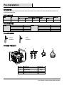
PERFORMANCE
SKU HP GPH of water @ Total Feet Of Lift Max. Lift
0 ft. 20 ft. 40 ft. 60 ft. 80 ft.
1001 222 714 5.5 HP 9000 7800 6300 4500 1800 90 ft.
SPECIFICATIONS
Pump Suction port diameter (in.) G2 in. Engine Model GH210-3
Discharge port diameter (in.) G2 in. Type Air-cooled, 4-stroke
Suction head lift (ft.) 20 Displacement (cc) 208
Total head lift (ft.) 90 Rated output (kW-r/min) 4/3600
Discharge capacity (GPH) 9000 Ignition system Transistor Magneto
TOOLS REQUIRED
Flathead
screwdriver
Phillips
screwdriver
PACKAGE CONTENTS
Part Description Quantity
A
Pump 1
B Joint assembly 2 sets
C Clamp 3
D Stainer 1
A
BCD

4
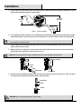
Installation
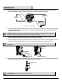
1. Place the unit as close to the water source as possible to minimize suction lift, obtain the best pumping performance, and aid in
priming. A typical portable installation is shown in Figure 1.
2. For a permanent installation, mount the unit on a foundation that will support the weight of pump and engine and also provide
stability while the pump is running. For most permanent installations, it is advisable to bolt the unit directly to the foundation.
NOTE: Settling and/or shifting during operation can cause piping to place excessive strain on the pump and may damage the pump
case. Set the pump on a hard level surface.
3. Connect suction hose (not included) to the pump suction. The hose must be rated to hold the suction pressure and prevent
collapse while the pump is running.
4. Make the suction hose a continuous rise from the water source to the pump. High spots can trap air and also make priming
difficult. Make sure all connections are tight and free of air leaks.
NOTE: Suction hose must be at least as large as the pump suction port in order for the pump to operate properly.
5. Install the strainer (provided with the pump) on the other end of the suction hose, and secure it with a hose clamp. The strainer
will help to prevent the pump from becoming clogged or damaged by debris.
WARNING: Never operate the pump without the strainer installed.
Discharge
head
Total head
(26m 85ft)
Figure 1 - Typical installation
Suction head
Suction hose
Clamp
Hose connector
Clamp
Suction hose
Suction
port
Washer
Pipe joint
Joint
Suction hose
Clamp
Strainer

5 HOMEDEPOT.COM
Please contact 1-844-883-1872 for further assistance.
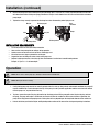
Installation (continued)
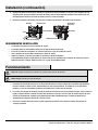
6. Connect discharge hose (not included) to the pump discharge port. It is best to use a short, large-diameter hose, because this
will reduce fluid friction and improve pump performance. A long or small-diameter hose will increase fluid friction and reduce
pump output.
7. Tighten the clamp securely to prevent the discharge hose from disconnecting under high pressure.
INSTALLATION REQUIREMENTS
□ Use reinforced hose to make the suction connection.
□ Hose must be strong enough to not collapse during operation.
□ Suction screen area must be at least four times suction pipe area.
□ All suction hose must slope up toward the suction port.
□ Support the hose and fittings to reduce strain on the pump case.
□ Depth of suction port must be at least four (4) times the diameter of suction hose to avoid forming vortexes.
Example: 2" Pipe x 4 = 8" minimum depth
Operation
NOTE: Do not start or run the pump dry or damage to the mechanical seal will result.
NOTE: Add engine oil before startup.
1. A self-priming pump only needs to be manually primed at the first start-up. Once primed, under normal conditions the pump will
reprime automatically at each subsequent start-up. If the pump is used in portable applications and the water has been drained
from the pump case, re-prime before start-up.
2. To prime, remove the water filler plug (6) from the top discharge port and fill the pump with water. Replace the plug and start
the pump. The pump will require a few minutes to evacuate air from the suction line. After several minutes of operation, the
pump will be fully primed and pumping water. Priming time will vary depending on the length and diameter of the suction line.
3. Refer to the Before you Start the Engine and Engine Operation sections of this manual for starting and operating instructions.
Clamp
Hose
connector
Discharge hose
Discharge hose
Clamp
Discharge port
Washer
Pipe joint
Joint

6
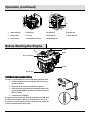
Operation (continued)
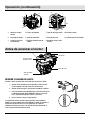
1. Recoil starter grip 4. Choke lever 7. Oil drain plug 10. Suction port
2. Ignition switch 5. Fuel cap 8. Discharge port 11. Pump drain cap
3. Fuel valve lever 6. Priming water filler plug 9. Oil fill and dipstick
CHECKING AND FILLING THE OIL
The engine is shipped without oil. It must be filled before starting the engine.
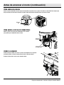
1. Fill oil by removing the fill cap and dipstick. Wipe off any excess
oil from the dipstick.
2. Add oil until the level reaches the bottom of the opening.
3. Check the oil level by pushing the cleaned dipstick into the oil fill
opening. DO NOT SCREW IT IN. Remove the dipstick and inspect it.
Add oil if needed.
4. Reinstall the cap and dipstick.
Oil capacity is 0.63 quarts (0.6 liter). Under normal conditions use 1OW-30 oil.
Use 1OW-40 oil if the engine is to be run in temperatures over 90°F (32°C).
The engine has a low-oil monitoring system. If the oil level drops too low, the
system will automatically turn off the engine.
5
4
3
2
8
10
7
11
1
9
6
Air filter
Gas tank
Oil drain plug
Muffler
Oil fill and dipstick
Oil plug
Before Starting the Engine

7 HOMEDEPOT.COM
Please contact 1-844-883-1872 for further assistance.
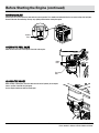
Before Starting the Engine (continued)
ADDING GASOLINE
Remove the fuel cap and fill the fuel tank with clean fresh gasoline. This should be unleaded fuel that has an octane rating of 86 or higher.
Do not fill the tank to overflowing. Clean up any spilled gasoline before starting the engine.
OPENING THE FUEL VALVE
Move the fuel valve lever to the right to allow fuel to the engine.
CLOSING THE CHOKE
When starting a cold engine, move the choke lever to the left (closed). As the engine
warms up move it towards the right (open).
A warm engine should start with the choke open.
Highest
level
Choke
lever
Fuel valve
lever

8
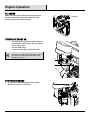
Engine Operation
FILL WATER
Before starting the engine, remove the filler plug from the pump
chamber, and completely fill the pump chamber with water.
Reinstall the filler plug and tighten it securely.
TURNING THE ENGINE ON
□ The ignition switch (1) controls the ignition. Move it to
the ON position to start the engine. The same control is
used to stop the engine.
□ Adjust the choke lever (3).
□ Pull the recoil starter grip (2) on the recoil starter.
NOTE: Before starting a cold engine, you MUST move the
choke lever (3) to the left (closed). As the engine warms up,
move it towards the right (open). A warm engine should
start with the choke open.
STOPPING THE ENGINE
□ Stop the engine by turning the ignition switch (1) to OFF.
□ Move the fuel valve lever (2) to OFF (left).
Filler plug
3
1
2
12

9 HOMEDEPOT.COM
Please contact 1-844-883-1872 for further assistance.
Repair and Maintenance
Adjust and maintain the gasoline engine strictly in accordance with the maintenance methods and instructions listed in this manual.
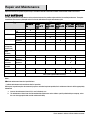
DAILY MAINTENANCE
The regular inspection and adjustment must be carried out to ensure the gasoline engine maintains its excellent performance. The regular
maintenance also ensures a prolonged service life. See the table below for regular maintenance cycle.
Item Maintenance Cycle
Each time of
Use
Every 1
month or 10
hours
Every 3
months of 20
hours
Every 6
months or 50
hours
Every 1 Year
or 100 Hours
Every 2 Years
or 200 Hours
Lubricating Oil Check the oil
level
■
Replacement
□ ■
Air Filte
r
Check
■
Cleaning
■
a
Spark Plug Check and
adjustment
■
Replacement
■
Spark
extinguisher
(optical part)
Cleaning
■
Bolt, nut, and
other
fasteners
Check Screwing up if necessary
Cooling fin Check
■
Max. no-load
speed
Check and
adjustment
■
b
Valve
clearance
Check and
adjustment
■
b
Combustion
chamber
Cleaning 200 hours later
Fuel strainer Check
■
b
Fuel tank Check
■
b
Fuel pipe Check
Every 2 years (replace when necessary)
b
Notes:
■
Indicates maintenance interval of specified items.
□
Indicates maintenance to be carried out after first operation.
With respect to gasoline engines for commercial purposes and under long-term operation, their maintenance intervals shall be appropriately
determined.
a. Increase the maintenance interval if it is used in the dusty area.
b. The maintenance of these items shall be conducted by maintenance service stations specially authorized by our company, unless
the users have appropriate tools and the maintenance ability.

10
Repair and Maintenance (continued)
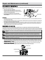
REPLACEMENT OF LUBRICATING OIL
Run the pump with water for five (5) minutes and then shut it down before replacing the engine’s lubricating oil. This ensures the quick and
complete release of the lubricating oil.
□ Check if the oil tank cover is tightened.
□ Unscrew the engine oil plug and tilt the engine towards the
cylinder head cover, drain the oil into an appropriate container
and then screw up the engine oil plug.
□ Unscrew the oil fill and dipstick, fill the recommended
lubricating oil through the oil filler and check the oil level (no
more than 600 ml).
Precautions:
□ It is recommended to replace the lubricating oil when there is no or little fuel in the fuel tank in case of fuel overflowing from the fuel
tank when the engine is tilted.
□ In case of lubricating oil overflowing, make sure to wipe off the oil. Wash hands with soap and water or detergent after contacting the
lubricating oil, and then wash hands with clean water.
□ Please dispose the waste lubricating oil and containers with methods in compliance with environmental protection requirements. It is
suggested to store the waste lubricating oil into a sealed container and deliver it to the local waste oil recycle bin for treatment. It is
forbidden to directly throw it into the dustbin or pour it into water.
MAINTENANCE OF AIR FILTER
The function of the air filter is to filtrate impurities and dust in the air so as to mix clean air with fuel for the sake of stable engine
performance. The dirty air filter will make the impurities and oil stains cover the element of the air filter, reduce the air capacity required by
the combustion of gasoline engine, and cause the disproportion of gas mixture, abnormal combustion and engine performance attenuation.
DANGER: Do not use gasoline or cleaning agent with low ignition point to clean the filtering element of the air filter, as a fire or explosion
may occur.
WARNING: Some solid impurities of high hardness directly into the combustion chamber of the engine will cause irretrievable fatal
damage to the engine. Therefore, the maintenance frequency shall be increased if the engine is used at a place with high dust content.
CAUTION: It is strictly prohibited to operate the gasoline engine in the case of not installing the filtering element of the air filter as it may
accelerate the wear and damage of the gasoline engine
□ The air filter of the engine is of a double-element structure (foam + paper). For the purpose of inspection, remove the air filter casing
and take out the filter element. The damaged filter element shall be duly replaced and usually replaced once during the maintenance.
□ Cleaning the foam filter element: Wash the foam filter element with cleaning agent, swish it after cleaning with fresh water, and air
dry before operation.
□ Cleaning the paper filter element: Lightly beat the filter element several times, and blow air from the inside to the outside with
compressed air (not exceeding 30 psi). Never use items such as a brush to clean the paper filter element.
Engine oil plug
Air cleaner base
Air cleaner cover
Foam filter element
Paper filter element

11 HOMEDEPOT.COM
Please contact 1-844-883-1872 for further assistance.
Repair and Maintenance (continued)
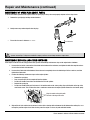
MAINTENANCE OF SPARK PLUG (MODEL F6RTC)
To ensure the normal operation of the engine, ensure the spark plug is always clean and properly adjusted as these steps show:
1. Remove the spark plug by twisting counterclockwise.
2. Gently remove any carbon deposits from the plug.
3.
Ensure the clearance is between
0.6~0.8mm.
WARNING: The spark plug must be securely tightened in the engine. Otherwise, the combustion chamber will be not airtight during
operation. The leakage of compressed air will reduce engine power and serious leakage will lead to engine failure.
MAINTENANCE BEFORE A LONG-TERM SHUTDOWN
If the engine will not be used for a long period of time, perform the following maintenance steps on the engine before shutdown:
1. Unscrew the fuel switch, unscrew the oil drain bolt at the bottom of the carburetor, and tighten the bolt after complete release
of fuel in the fuel tank and carburetor.
2. Unscrew the oil drain bolt at the bottom of the crankcase to completely release the lubricating oil in the crankcase, and then
tighten the oil drain bolt.
3. Perform the following maintenance steps on the engine cylinder:
□ Remove the spark plug.
□ Pour a teaspoon (5cc) of clean engine oil into the cylinder.
□ Pull the start handle several times to distribute the oil in the cylinder.
□ Reinstall the spark plug.
□ Pull the start handle slowly until resistance is felt and the notch on the starter pulley aligns with the hole at the top of the
recoil starter cover. This will close the valves so moisture cannot enter the engine cylinder. Return the start handle gently.
4. Wipe off the oil stain and dust on the external surface with a cleaning cloth and remove the dirt between the cooling fins, so as
to keep the gasoline engine clean. After cleaning, store the engine in a clean, dry and ventilated location.
0.6~0.8 mm
Align the notch on the pulley with
the hole at the top of the cover.

12
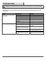
Troubleshooting
CAUTION: Do not disassemble this pump without the manufacturer’s permission. The warranty does not cover unauthorized disassembly.
If the remedial actions in this table do not eliminate the faults or the faults encountered are unmentioned in this table, please contact
Customer Service.
Problem Probable Cause Resolution
The engine experiences difficulty starting
up, does not start up, or does not produce
sufficient power.
Fuel is insufficient. Refill recommended fuel.
On/off switch is not turned on. On/off switch is turned to “On” position.
Choke is not closed. Close the choke.
Too much carbon deposit in spark plug. Eliminate carbon deposit.
Gap of spark plug is not correct. Adjust gap of spark plug to specified range.
Spark plug is damaged. Replace spark plug.
Use engine oil of poor quality or engine oil
deteriorates.
Replace engine oil.
Overload or overheat. Check operating status.
Engine oil is insufficient. Add appropriate volume of engine oil.
The pump is either not pumping water or
there is not enough pressure when running.
There is blockage in the filter. Remove the blockage.
There is inadequate priming in the pump. Unscrew the water filling plug and fill with
clean water.
Blockage, drop-out, leakage of water pipe,
or too long or insufficient diameter of the
pipe.
Check the water pipe.
Water suction does not sink into water. Adjust the position of water suction, so that
it is completely submerged in water.
Water suction pipe joint leaks. Check water pipe joint.
The installation height of the water pump is
too high.
Decrease the installation height of the water
pump.

13 HOMEDEPOT.COM
Please contact 1-844-883-1872 for further assistance.
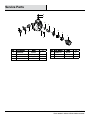
Service Parts
Part Part Number Name
Qty
Part Part Number Name
Qty
1 100022246
Straine
r
1
5 100022187 Washer
2
2 100022225
Clamp 3
6 100021938 Plug
2
3 100030202
Pipe joint 2
7 100021965 O-ring
2
4 100022201-0001 Joint 2
6
7
5
7
6
2
3
4
5
4
3
2
2
1

Questions, problems, missing parts? Before returning to the store,
call Everbilt Customer Service
8 a.m. - 6 p.m., EST, Monday-Friday
1-844-883-1872
HOMEDEPOT.COM
Retain this manual for future use.

GRACIAS
Apreciamos la confianza que ha depositado en Everbilt por la compra de esta bomba. Nos esforzamos por crear continuamente productos de calidad
diseñados para mejorar su hogar. Visítenos en internet para ver nuestra línea completa de productos disponibles para sus necesidades de mejorar su
hogar. ¡Gracias por elegir a Everbilt!
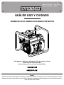
Núm. de artículo 1001 222 714
Núm. de modelo WG20
GUÍA DE USO Y CUIDADO
BOMBA DE AUTO CEBADO ACCIONADA POR MOTOR
¿Tiene preguntas, problemas, o faltan piezas? Antes de regresar a la tienda,
llame a Servicio al Cliente de Everbilt
de lunes a viernes de 8 a.m. a 6 p.m., hora local del Este
1-844-883-1872
HOMEDEPOT.COM

2
Tabla de contenido
Tabla de contenido ....................................................... 2
Información de seguridad ............................................ 2
Garantía .......................................................................... 2
Pre-instalación .............................................................. 3
Instalación ...................................................................... 4
Funcionamiento ............................................................. 5
Antes de arrancar el motor .......................................... 6
Operación del motor..................................................... 8
Reparación y mantenimiento ...................................... 9
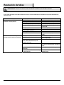
Resolución de fallas ................................................... 12
Piezas de servicio ....................................................... 13
Información de seguridad
ADVERTENCIA: Peligro de incendio y explosión. La gasolina
puede explotar. Guarde la gasolina lejos del motor. Agregue
gasolina al motor solo cuando el motor esté apagado.
ADVERTENCIA: Peligro de explosión. Superficie caliente. El
motor se pone muy caliente durante la operación. No toque la
superficie del motor. Mantenga alejados a los niños. Deje que el
motor se enfríe antes de moverlo a interiores.
ADVERTENCIA: Humos mortales. Monóxido de carbono
Nunca ponga a funcionar el motor en un espacio cerrado.
Úselo únicamente en exteriores con bastante ventilación.
ADVERTENCIA: Este producto y los accesorios
relacionados contienen sustancias químicas que el Estado
de California sabe producen cáncer, defectos de nacimiento
u otros daños reproductivos.
IMPORTANTE: Para un posible mejor desempeño y operación
continua y satisfactoria, lea estas instrucciones antes de instalar
su nueva bomba. En caso de que se requiera servicio, este
manual puede ser una guía valiosa, debe mantenerse cerca de la
instalación para una referencia rápida.
Asegúrese de que la temperatura ambiente del motor de la
bomba de agua esté a +5°C~+40°C.
Garantía
El fabricante garantiza que este producto está libre de defectos en materiales y mano de obra por un periodo de seis (6) meses a partir de la
fecha de compra. Esta garantía aplica únicamente al comprador consumidor final y únicamente para los productos usados en condiciones
de uso y servicio normal. Si en seis meses este producto se encuentra, luego de su revisión por parte del fabricante, que está defectuoso en
materiales o mano de obra, la única obligación del fabricante y la única reparación, es reparar o reemplazar el producto a discreción del
fabricante, siempre y cuando el producto no ha sido dañado por mal uso, abuso, accidente, modificaciones, alteraciones, negligencia o mal
manejo. Es necesario su recibo de compra para determinar la elegibilidad de la garantía.
El comprador debe pagar todos los cargos por mano de obra y envío necesarios para reemplazar el producto cubierto por esta garantía.
Esta garantía no cubre productos que han sido dañados como resultado de un accidente, mal uso, abuso, negligencia, alteración,
instalación o mantenimiento inadecuados, o no operarlo de acuerdo con las instrucciones suministradas con los productos, o fallas
operativas causadas por corrosión, óxido, u otros materiales extraños en el sistema.
Las solicitudes para servicio bajo esta garantía se harán devolviendo el producto defectuoso al fabricante lo más pronto posible después del
descubrimiento de cualquier presunto defecto. El fabricante posteriormente emprenderá acción correctiva tan pronto como sea
razonablemente posible.
El fabricante no garantiza ni deniega específicamente ninguna garantía, sea expresa o implícita, o idoneidad para un propósito particular,
que no sea la garantía contenida en el presente. Esta es la reparación exclusiva y están excluidos toda responsabilidad por cualquier y todo
daño indirecto o consecuente o fueren lo que fueren los gastos
Algunos estados no permiten la exclusión o la limitación de los daños incidentales o consecuentes o limitaciones sobre la duración de la
garantía implícita, por lo tanto, es posible que las exclusiones o las limitaciones antes indicadas no correspondan a usted. Esta garantía le
otorga derechos legales específicos y también puede tener otros derechos que varían de un estado a otro.
Póngase en contacto con el Equipo de Servicio al Cliente llamando al 1-844-883-1872 o visite www.HomeDepot.com.

3 HOMEDEPOT.COM
Póngase en contacto con el 1-844-883-1872 para asistencia adicional.
Pre-instalación
APLICACIÓN
La bomba es una bomba de agua limpia y no puede bombear aguas residuales ni agua de mar. Evite la arena, manchas de aceite u otro
líquido contaminante que causará corrosión de las piezas.
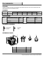
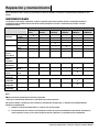
DESEMPEÑO
SKU HP GPH de agua a pies totales de elevación Elevación
máxima
0 pies 20 pies 40 pies 60 pies 80 pies
1001 222 714 5.5 HP 9000 7800 6300 4500 1800 90 pies
ESPECIFICACIONES
Bomba
Diámetro del puerto de succión (pulg.) G2 pulg.
Motor
Modelo GH210-3
Diámetro del puerto de descarga (pulg.) G2 pulg. Tipo Enfriado por aire, 4
carreras
Levantamiento de la cabeza de
succión (pies)
20 Desplazamiento (cc) 208
Levantamiento de la cabeza total (pies) 90 Salida nominal (kW-r/min) 4/3600
Capacidad de descarga (GPH) 9000 Sistema de ignición Magneto del transistor
HERRAMIENTAS REQUERIDAS
Destornillador de
punta plana
Desarmador
Phillips
CONTENIDO DEL PAQUETE
Pieza Descripción Cantidad
A
Bomba 1
B Ensamblaje de junta 2 juegos
C Abrazadera 3
D Filtro 1
A
BCD

4
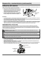
Instalación
1. Coloque la unidad lo más cerca posible de la fuente de agua para minimizar el levantamiento de succión, obtener el mejor
desempeño de bombeo y ayudar en el cebado. En la Figura 1 se muestra una instalación portátil típica.
2. Para una instalación permanente, monte la unidad en una base que soporte el peso de la bomba y motor y también proporcione
estabilidad mientras la bomba esté funcionando. Para la mayoría de instalaciones permanentes, se recomienda empernar la
unidad directamente a la base.
NOTA: El asentamiento y desplazamiento durante la operación puede hacer que la tubería coloque tensión excesiva en la bomba y
puede dañar la cubierta de la bomba. Coloque la bomba sobre una superficie dura y nivelada.
3. Conecte la manguera de succión (no incluida) en la succión de la bomba. La manguera debe tener capacidad nominal para
soportar la presión de succión y evitar el colapso mientras la bomba está funcionando.
4. Haga que la manguera de succión ascienda continuamente de la fuente de agua a la bomba. Los sitios altos pueden atrapar aire
y también volver difícil el cebado. Asegúrese de que las conexiones estén apretadas y que no hayan fugas de aire.
NOTA: La manguera de succión debe ser al menos tan grande como el puerto de succión de la bomba para que la bomba funcione
adecuadamente.
5. Instale el filtro (proporcionado con la bomba) en el otro extremo de la manguera de succión y asegúrelo con una abrazadera de
manguera. El filtro ayudará a evitar que la bomba se obstruya o dañe por desechos.
ADVERTENCIA: Nunca opere la bomba sin tener instalado el filtro.
Cabeza de
descarga
Cabeza total
(26 m 85 pies)
Figura 1 – Instalación típica
Cabeza
de succión
Manguera de succión
Abrazadera
Conector de
manguera
Abrazadera
Manguera
de succión
Puerto de
succión
Arandela
Junta de tubería
Junta
Manguera de succión
Abrazadera
Filtro

5 HOMEDEPOT.COM
Póngase en contacto con el 1-844-883-1872 para asistencia adicional.
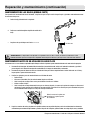
Instalación (continuación)
6. Conecte la manguera de descarga (no incluida) en el puerto de descarga de la bomba. Es mejor usar una manguera corta de
diámetro grande, porque esto reducirá la fricción del fluido y mejorará el desempeño de la bomba. Una manguera larga y de
diámetro pequeño aumentará la fricción del fluido y reducirá la salida de la bomba.
7. Apriete con seguridad la abrazadera para evitar que la manguera de descarga se desconecte bajo alta presión.
REQUERIMIENTOS DE INSTALACIÓN
□ Use manguera reforzada para hacer la conexión de succión.
□ La manguera debe ser suficientemente fuerte para no colapsar durante la operación.
□ El área de la pantalla de succión debe ser al menos cuatro veces el área de la tubería de succión.
□ Toda la manguera de succión debe ascender hacia el puerto de succión.
□ Soporte la manguera y accesorios para reducir la tensión en la cubierta de la bomba.
La profundidad del puerto de succión debe ser al menos cuatro (4) veces el diámetro de la manguera de succión para evitar la
formación de vórtices. Ejemplo: Tubería de 2 pulg. x 4 = 8 pulg. de profundidad mínima
Funcionamiento
NOTA: No arranque ni haga funcionar la bomba seca o podrían resultar daños al sello mecánico.
NOTA: Agregue aceite de motor antes del arranque.
1. Una bomba de auto cebado solo necesita ser cebada manualmente en el primer arranque. Una vez cebada, bajo condiciones
normales la bomba se volverá a cebar automáticamente en cada arranque posterior. Si la bomba se usa en aplicaciones
portátiles y el agua se ha drenado de la cubierta de la bomba, vueva a cebar antes del arranque.
2. Para cebar, retire el tapón de llenado de agua (6) del puerto de descarga superior y llene la bomba con agua. Vuelva a colocar el
tapón y arranque la bomba. La bomba necesitará unos minutos para evacuar el aire de la línea de succión. Después de varios
minutos de funcionamiento, la bomba estará completamente cebada y bombeando agua.. El tiempo de cebado variará
dependiendo de la longitud y diámetro de la línea de succión.
3. Consulte las secciones Antes de arrancar el motor y Operación del motor de este manual para obtener instrucciones de
arranque y operación.
Abrazadera
Conector de
manguera
Manguera de descarga
Puerto de descarga
Abrazadera
Discharge port
Arandela
Junta de tubería
Junta

6
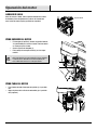
Operación (continuación)
1. Manija de arranque
retráctil
4. Palanca del ahogador 7. Tapón de drenaje de aceite 10. Puerto de succión
2. Interruptor de ignición 5. Tapón de combustible 8. Puerto de descarga 11. Tapón de drenaje de la bomba
3. Palanca de la válvula
de combustible
6. Tapón de llenado de agua de
cebado
9. Llenado de aceite y varilla
de nivel
REVISIÓN Y LLENADO DEL ACEITE
El motor se envía sin aceite. Debe ser llenado antes de arrancar el motor.
1. Agregue aceite quitando la tapa de llenado y la varilla de nivel.
Limpie cualquier exceso de aceite de la varilla de nivel.
2. Agregue aceite hasta que el nivel alcance el fondo de la abertura.
3. Revise el nivel del aceite introduciendo la varilla de nivel limpia en
la abertura de llenado. NO LA ATORNILLE. Extraiga la varilla de
nivel e inspecciónela. Agregue aceite si es necesario.
4. Vuelva a instalar la tapa y la varilla de nivel.
La capacidad de aceite es de 0.63 cuartos (0.6 litros). Bajo condiciones
normales use aceite 1OW-30. Use aceite 1OW-40 si el motor va a funcionar a
temperaturas mayores de 90°F (32°C). El motor tiene un sistema de
monitoreo de bajo nivel de aceite. Si el nivel del aceite baja demasiado, el
sistema apagará automáticamente el motor.
5
4
3
2
8
10
7
11
1
9
6
Filtro de aire
Tanque de gas
Tapón de llenado
de aceite
Silenciador
Llenado de aceite
y varilla de nivel
Tapón de aceite
Antes de arrancar el motor
Page is loading ...
Page is loading ...
Page is loading ...
Page is loading ...
Page is loading ...
Page is loading ...
Page is loading ...
Page is loading ...
-
 1
1
-
 2
2
-
 3
3
-
 4
4
-
 5
5
-
 6
6
-
 7
7
-
 8
8
-
 9
9
-
 10
10
-
 11
11
-
 12
12
-
 13
13
-
 14
14
-
 15
15
-
 16
16
-
 17
17
-
 18
18
-
 19
19
-
 20
20
-
 21
21
-
 22
22
-
 23
23
-
 24
24
-
 25
25
-
 26
26
-
 27
27
-
 28
28


Ask a question and I''ll find the answer in the document
Finding information in a document is now easier with AI
in other languages
Related papers
-
Everbilt WG20 User guide
-
-
Everbilt SUP54-HD User manual
-
-
Everbilt EFLS20-HD User guide
-
-
-
-
-
Everbilt HDEFR50W Operating instructions
Other documents
-
Simer 4955 User manual
-
Flotec FP5455 Owner's manual
-
Simer 4955-01 User manual
-
Ducati DCW25 Owner's manual
-
red lion Engine-Driven Aluminum TRANSFER Pump Operating instructions
-
-
 Pro-source EDP55RV-01 Engine Drive Self-Priming Pump Owner's manual
-
 Mi-T-M Chemical/Liquid Fertilizer Pump Owner's manual
-
Generac Trash Pump G0069200 User manual

