2
Table of Contents
Table of
Contents .......................................................... 2
Safet
y Information ......................................................... 2
Warranty .........................................................................
3
Pre-installation ..............................................................
4
Installation .....................................................................
5
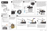
Well Pipe Installation
...............................................................5
Cased Well/Dug Well Installation
.............................................5
Driven Point Installation
...........................................................6
Pipe from
Well to Pump ...........................................................6
Pump/Piping In
stallation ..........................................................6
Electrical Settings
......................................................... 7
Wiring
Connections ...................................................... 7
Operation .......................................................................
8
Care and Cleaning
........................................................ 9
Troubleshooting ..........................................................
10
Service
Parts ............................................................... 11
Safety Information
BEFO
RE YOU OPERATE THIS PUMP
1. Avoid Pressu
re Burns/Explosion
2. Avoid Electric Shock
□ Fill the pump with water. Ensure the pump body is filled
with water to discharge.
□ Motor’s Electrical Settings: Set the motor to the proper
voltage (voltage supplied to the pump).
IMPORTANT SAFETY I
NSTRUCTIONS
SAVE THESE INSTRUCTIONS
– This manual contains important
instructions that must be followed during installation, operation,
and maintenance of this pump. Also familiarize yourself with the
following safety symbols and their meanings:
DANGER: Indicates a h
azard which, if not avoided, will
result in d
eath or serious injury.
WARNING: Indicates a hazard which, if not avoided,
could result in death or serious injury.
CAUTION: Indicates a haz
ard which, if not avoided, could
result in minor
or moderate injury.
NOTICE: Addresses practices not related t
o personal injury.
Carefu
lly read and follow all safety instructions in this
manual and on the pump.
Keep safety labels in good condition. Replace missing or
damaged safety labels.
WARNING: R
isk of explosion. The pump body may
explod
e if used as a booster pump.
CAUTION: Risk
of burns. Do not touch an operating
motor. M
otors are designed to operate at high
temperatures. To avoid burns when servicing the pump,
allow
it to cool for 20 minutes after shut down before
handli
ng.
CAUTION: Do not allow the pump or any system
component to freeze. To do s
o will void the warranty.
CAUTION: Only use this pump t
o pump water.
CAUTION: Periodically inspect pump and system
c
omponents.
CAUTION: Wear safety glasses at all times when working
on pumps.