Everbilt EFLS20-HD Operating instructions

Type
Operating instructions

Everbilt EFLS20-HD is a powerful 2 HP plastic lawn sprinkler pump designed for efficient and reliable water distribution in residential irrigation systems. With a maximum flow rate of 83 gallons per minute and a discharge pressure of up to 56 PSI, it can effortlessly handle the demands of large lawns and gardens. Its durable construction and simple operation make it an ideal choice for homeowners seeking a dependable watering solution.

Everbilt EFLS20-HD is a powerful 2 HP plastic lawn sprinkler pump designed for efficient and reliable water distribution in residential irrigation systems. With a maximum flow rate of 83 gallons per minute and a discharge pressure of up to 56 PSI, it can effortlessly handle the demands of large lawns and gardens. Its durable construction and simple operation make it an ideal choice for homeowners seeking a dependable watering solution.

THANK YOU
We appreciate t
he trust and confidence you have placed in Everbilt through the purchase of this pump. We strive to continually create quality
products designed to enhance your home. Visit us online to see our full line of products available for your home improvement needs. Thank you for
choosing Everbilt!
Item #1001 092 236
1001 092 238
1001 092 241
M
odel #EFLS10-HD
EFLS15-
HD
EFLS20-HD
USE AND CARE GUIDE
PLASTIC LAWN SPRINKLER PUMP
Questions, problems, missing parts? Before returning to the store,
call Everbilt Customer Service
8 a.m. - 6 p.m., EST, Monday-Friday
1-844-883-1872
HOMEDEPOT.COM
2
Table of Contents
Table of
Contents .......................................................... 2
Safet
y Information ......................................................... 2
Warranty .........................................................................
3
Pre-installation ..............................................................
3
Installation .....................................................................
5
Well Pipe Installation
...............................................................5
Cased Well/Dug Well Installation
.............................................5
Driven Point Installation ...........................................................5
Surface Water Installation
..........................................................6
Lawn Sprinkling Application
....................................................6
Pump/Piping In
stallation ..........................................................6
Electrical Settings
......................................................... 7
Wiring
Connections ...................................................... 7
Operation .......................................................................
8
Care and Cleaning
........................................................ 9
Troubleshooting ..........................................................
10
Service Parts ............................................................... 11
Safety Information
BEFO
RE YOU OPERATE THIS PUMP
1. Avoid Pressu
re Burns/Explosion
2. Avoid Electric Shock
Fill the pump with water. Ensure the pump body and suction
pipe is filled with water completely.
Motor’s Electrical Settings: Set the motor to the proper
voltage (voltage supplied to the pump).
IMPORTANT SAFETY I
NSTRUCTIONS
SAVE THESE INSTRUCTIONS
– This manual contains important
instructions that must be followed during installation, operation,
and maintenance of this pump. Also familiarize yourself with the
following safety symbols and their meanings:
DANGER: Indicates a h
azard which, if not avoided, will
result in death or serious injury.
WARNING: Indicates a haz
ard which, if not avoided,
could resu
lt in death or serious injury.
CAUTION: Indicates a hazard which, if not avoided, could
result in minor or moderate injury.
NOTICE: Addresses practices not related to personal injury.
Carefu
lly read and follow all safety instructions in this
manual and on the pump.
Keep safety labels in good condition. Replace missing or
damaged safety labels.
WARNING: Risk of explosion. The pump body may
explode if used as a booster pump.
CAUTION: Risk of burns. Do not touch an operating
motor. Motors are designed to operate at high
temperatu
res. To avoid burns when servicing the pump,
allow
it to cool for 20 minutes after shut down before
handling.
CAUTION: Do not allow the pump or any system
component to freeze. To do so will void the warranty.
CAUTION: Only use this pump t
o pump water.
CAUTION: Periodically inspect pump and system
components.
CAUTION: Wear safety glasses
at all times when working
on pumps.
Pipe from
Well to Pump ...........................................................6
READ AND UNDERSTAND THIS MANUAL
WARNING:
Do not use this pump for water pressure
booster applications. The pump housing is rated for 55 PSI
MAX.
3
HOMEDEPOT.COM
Please contact 1-844-883-1872 for further assistance.
Warranty
The manufactur
er warrants to the original consumer purchaser (“Purchaser” or “You”) that its products are free from defects in material
and workmanship for a period of twelve (12) months from the date of the original consumer purchase. If, within twelve (12) months from
the original consumer purchase, any such product shall prove to be defective, it shall be repaired or replaced at the manufacturer’s option,
subject to the terms and conditions set forth herein. Note that this limited warranty applies to manufacturing defects only and not to
ordinary wear and tear. All mechanical devices need periodic parts and service to perform well. This limited warranty does not cover repair
when normal use has exhausted the life of a part or the equipment.
The original purchase receipt and product warranty information label are required to determine warranty eligibility. Eligibility is based on
purchase date of original product – not the date of replacement under warranty. The warranty is limited to repair or replacement of original
purchased product only, not replacement product (i.e. one warranty replacement allowed per purchase). Purchaser pays all removal,
installation, labor, shipping, and incidental charges.
For parts or troubleshooting assistance, DO NOT return the product to your retail store - contact Everbilt Customer Service at
1-844-883-1872.
Claims made under this warranty shall be made by returning the product (except sewage pumps, see below) to the retail outlet where it
was purchased or to the factory immediately after the discovery of any alleged defect. The manufacturer will subsequently take corrective
action as promptly as reasonably possible. No requests for service will be accepted if received more than 30 days after the warranty
expires. Warranty is not transferable and does not apply to products used in commercial/rental applications.
Pre-installation
BEFO
RE YOU INSTALL THIS PUMP
WARNING: Risk of expl
osion. Do not ground to a gas supply line. The pump body may explode if used as a booster pump or other than a
lawn sprin
kling application.
CAUTION: Risk
of burns. Do not touch an operating motor. Motors are designed to operate at high temperatures. It is protected from heat
damag
e during operation by an automatic internal cutoff switch. To avoid burns when servicing the pump, allow it to cool for 20 minutes after
shut down befor
e handling.
The pump’s wa
ter suction inlet must not be more than 20 ft. above the water level.
Long runs and many fittings increase friction and reduce water flow to the pump. Locate the pump as close to the water source as
possible. Use as few elbows and fittings as possible. Ensure the suction line is straight and angles up toward the pump.
Ensure the well and pipe are clear of sand, dirt, and scale. Foreign matter will plug the pump and void the warranty. Use new pipe
for best results.
Protect the pump and all piping from freezing.
Freezing will split pipe, damage the pump and void the warranty. Check locally for frost protection requirements. The pump cannot
be installed below the frost line and the pump must be insulated.
Foot or check valves (not included) must be installed in the suction pipe to optimize pump suction.
Ensure all pipes and valves are clean and in good shape.
Ensure there are no air pockets in the suction pipe.
Ensure there are no leaks in the suction pipe. Use Teflon tape or other approved sealants to seal pipe joints.
Unions installed near the pump and well will aid in servicing. Leave room to use wrenches.
4
Pre-installation
PERFORM
ANCE DATA
SKU HP
DISTANCE O
F
PUMP ABOVE
WATER
DISCHARGE PR
ESSURE
10
20
30
40
50
GALLONS PER
MINUTE
236
5
ft. 56 45 31 17 --
10
ft. 49 42 28 12.5 --
15 ft. 48 39 24 8 --
20
ft. 45 37 20 -- --
1
1/2
5 ft. 67 61 48 33 --
10
ft. 61 56 45 26 --
15
ft. 56 54 44 20 --
20 ft. 46 44 37 11 --
2
5 ft. 83 71 56 41 17
10
ft. 77 67 54 36 8
15
ft. 76 65 50 32 --
20
ft. 75 62 48 28 --
1 092
1001
092 1001 238
092 1001 241
Outlet
1 1/2 in.
Inlet
2 in.
1 1/2 in.
2 in.
2 in.
2 in.
(continued)
Suction/Discharge
pipe
Thread sealant
tape
Check valve
Elbow
Union
Gate valve
Priming tee
MATERIAL
S REQUIRED (NOT INCLUDED)
1-1/2 in. or 2 in.
2 in.
1-1/2 in. or 2 in.
1-1/2 in. or 2 in.
1-1/2 in. or 2 in.
1-1/2 in. or 2 in.
Note: Please select suitable materials based on inlet and outlet size.(see page 4)
Pressure gauge
Pressure relief valve
Min
Min
Min
(recommended)
2 in. NPT
2 in. NPT strainer
basket with
1/8 in. holes
Before using thi
s pump, ensure you have the appropriate items based on the installation technique from the following pages.
IMPORTANT: Do not use pipe or fittings on suction side of pump less than 2 in.! This will
restrict suction and reduce priming ability and
performance.
Foot valve
with strainer
5
HOMEDEPOT.COM
Please contact 1-844-883-1872 for further assistance.
WELL PIPE INSTALLATION
Use the installa
tion methods provided in this chapter that match with your water source.
CASED WELL/DUG WELL INSTALLATION
1. Inspect the
foot or in line check valve to be sure it works
freely. Inspect the strainer to be sure it is clean and
secure.
2. If using a foot valve, connect the foot valve and strainer to
the first length of suction pipe and lower the pipe into the
well. Add sections of pipe as needed, using Teflon tape on
the male threads. Use 2 in. pipe for suction pipe. Be
sure all suction pipe is leak proof or the pump will lose
prime and fail to pump. Install foot valve 10 to 20 ft. (3 to 6
m) below the lowest level to which water will drop while
the pump is operating (pumping water level). Your well
driller can furnish this information.
3. To prevent sand and sediment from entering the pumping
system, a foot valve/strainer should be at least 5 ft. (1.5 m)
above the bottom of the well.
4. When proper depth is reached, install a sanitary well seal
over the pipe and in the well casing. Tighten bolts to the
seal casing.
5. When using a foot valve, a priming tee and plug are
recommended.
Pr
iming plug
Priming tee
2
0 feet (6m) max.
10-20 fe
et (3-6m)
Starting water
level (pump off)
Drawdown water
level (pump on)
Foot
Valve/Strainer
Suction pipe
Well seal
A
t le
ast 5 feet (1.5m
)
Installation
NOTICE: It is recommend that pump be installed in well ventilated enclosure.
DRIVEN P
OINT INSTALLATION
1. Connect suctio
n pipe to the drive point. Keep the horizontal
pipe run as short as possible. Use Teflon tape on male pipe
threads. Multiple well points may be necessary to provide
sufficient water to the pump.
2. Install a check valve in the horizontal pipe. The flow arrow
on the check valve must point toward the pump.
T
o sprinkler
heads
To sprinkler
heads
Multiple
well heads
Check
valve
Driven point installation,
multiple well points
Disc
harge pipe
Gate valve
6
Installation (continued)
SURFACE WATER INSTALLATION
PIPE FROM SOURCE TO PUMP
Pump performa
nce will be decreased if the pipe diameter is less
than the inlet size of the pump. In proper installation, the pipe size
equals the inlet size.
To aid priming, install a check valve or foot valve, depending on
Be sure the check valve flow arrow points toward the pump.
Pipe from pump to sprinkler heads discharge pipe size should be
increased to reduce pressure losses caused by friction on long pipe
runs:
Up to 100 ft. (30.5 m) run: Same size as pump discharge
port.
100 ft. – 300 ft. (30.5 – 91.4 m) run: Increase one pipe size.
300 ft. – 600 ft. (91.4 – 182.9 m) run: Increase two pipe
sizes.
PUMP/PIPING INSTALLATION
If turning the
pump on and off by pressure, a pressure switch and
tank are required. For proper installation and operation instructions
call Customer Service.
Use rigid pipe. Do not use hose or plastic tubing. See “Well Pipe
Installation” for more information.
Use only PTFE pipe thread sealant tape to joint compounds for
making all threaded connections to the pump itself.
Do not use pipe joint compounds on plastic pumps as they can
react with the plastic in pump components.
If the suction pipe has any leak, the pump will not be
able to pull water from the well.
1. Bolt the pump to solid, level foundation.
2.
Support all piping connected to the pump.
3. Wrap 1-1/2 to 2 layers of Teflon tape clockwise (as you
face the end of the pipe) on all male threads being
attached to pump.
4. Tighten joints hand tight plus 1-1/2 turns. Do not
overtighten.
5. Replace the prime plug with a pressure gauge. This will aid
in sizing zones, troubleshooting, and following the pump
performance chart.
NOTE: For long
horizontal pipe runs, install a priming
tee betwe
en the check valve and well head. See the
figure in th
e Cased Well/Dug Well Installation section
for further r
eference.
LAWN SP
RINKLING APPLICATION
This pump is designed for lawn irrigating system. When properly
adequate water and pressure from any of the
sources.
Foot valve with strainer (1/8 in. hole size) attached to PVC pipe.
Vertical from surface water to pump
1.
2.
Horizontal from surface water to pump
Foot Valve
with Strainer (1/8 in. hole size)
Check Valve
Strainer Basket
installed it will deliver
described
PIPE FROM PUMP TO END USE APPLICATION
USE NEW PIPE FOR BEST RESULTS
Make sure that all pipe joints in the suction pipe are air tight as well
as water tight.
Strainer (1/8 in.hole size ) and/or strainer basket installed
Install check valve in PVC pipe near pump.
at end of PVC suction pipe.
the installation configuration as shown above.
(1/8 in. hole size)
7
HOMEDEPOT.COM
Please contact 1-844-883-1872 for further assistance.
Electrical Settings
WARNING: Disconnect power before working on the pump, motor, pressure switch, or wiring.
CAUTION: The motor may b
e hot. Allow the motor to cool for 20 minutes after shut down.
CAUTION: Water pressure may have built up in the pump, pipes, or tank. Drain water to relieve pressure.
Wiring Connections
Screws
Motor Cover
WARNING: Risk of el
ectric shock. Can shock, burn, or kill.
1. To avoid dangerous or fatal electrical shock, turn OFF power to the motor before working on electrical
con
nections.
2. Grou
nd the motor before connecting to electrical power supply. Failure to ground the motor can cause severe or
fatal electrical shock hazard.
3. Supply voltage must be within +/- 10% of the nameplate voltage. Incorrect voltage can cause fire or damage the
motor and voids the warr
anty. If in doubt consult a licensed electrician.
4. Use a
wire size specified in the Wiring Chart (below). If possible, connect the pump to a separate branch circuit
with no other appliances on it.
5. Do not ground to a gas suppl
y line.
6. Set the motor according to the
7. If the diagram
on the motor cover plate differs fr om the diagrams in this section, follow the diagram on the
8.
If this procedure or the wiring diagrams are confusing, consult a licensed electrician.
diagram on the motor cover plate.
motor cover plate.
MOTOR VOLTAGE SETTINGS
Motors are designed to run on
either 115 volt or 230 volt power.
Ensure the motor’s voltage is set to match the voltage being
supplied to your motor from the electrical source.
plate. Next slide the voltage conversion switch to the correct voltage.
To set your motor to the correct voltage, first remove the rear motor cover
Set for 115V
Set for 230V
115
L1
L2
230
L1
L2
HOT
To Breaker
To Breaker
Neutral
HOT
To Breaker
To Breaker
HOT
8
Operation
WARNING: Hazardous Pressure. Install a pressure relief valve in the discharge pipe. Release all pressure on the system before working on
any component.
WARNING: Risk of explosion and scalding. NEVER run the
pump against a closed discharge. To do so can boil water
inside th
e pump, causing hazardous pressure in the unit,
risk of ex
plosion, and possibly scalding persons handling
the pump. Replace the priming plug with a pressure gauge
to monitor the pressure so that is i
t not allowed to exceed
the maximum pu
mping pressures according to the
performance chart.
To prevent expl
osion be sure the discharge (valve, pistol grip hose
nozzle, etc.) is open whenever the pump is running. Monitor the
pump body and piping temperature. The motor will warm up; this is
normal. If the pump body or piping begins to feel warm to the touch,
shut off the pump and allow the system to cool. Release all pressure
in the system and refill the pump and piping with cold water.
PRIMING THE PUMP
Pri
ming refers to pump expelling all air in the system and beginning to move water from its source out into the system. It does not refer only
to pouring water into the pump (although pouring water in is usually the first step).
CAUTION: Risk of burns. NEVER run the pump dry. Running the pump without water may cause the pump to overheat, damaging the seal
and possibly causing burns to persons handling the pump. Fill the pump with water before starting.
1. Remove the priming plug.
2. Make sure suction and dischar
ge valves and any hoses on the discharge side of the pump are open.
3. Fill the pump and suction pipe with water.
4. Replace the priming plug using Teflon tape on the threads. Tighten the plug. If the priming tee and plug have been provided for the
long horizontal run, fill the suction pipe through this tee and replace the plug. (Use Teflon tape on plug.)
5. Start the pump. Water should be produced in 10 minutes or less. The time depends on the depth to the water (not more than 20 ft.
(6 m)) and length of horizontal run (10 ft. (3 m)) of horizontal suction pipe = 1 ft. ((30.5cm) of vertical lift due to friction losses in
pipe). If no water is produced within 10 minutes, stop the pump, release all pressure, remove the priming plug, refill, and try again.
Fill pump
befor
e starting
RECOMMENDED WIRE AND
FUSE SIZES FOR 115 AND 230 VOLTS
MOT
OR HP
V
OL
TS
FULL LOAD
A
MP
BRANCH
FUSE/
RATING AMP
A
WG MIN. WIRE
SIZE (mm
2
)
DISTANCE
IN FEET FROM MOTOR TO SUPPLY
0-100 101-200 201-300 301-400 401-500
A
WG WIRE SIZE
(mm
2
)
1 10/14 (5.5/2) 8/14 (2/2) 6/14 (14
/
2) 6/12 (14/3) 4/10 (21/5.5)
30/15
10/14 (5.5/2) 10/14 (5.5/2) 8/14 (8.4/2) 6/12 (14/3) 4/10 (21/5.5) 4/10 (21/5.5)
2
1
15/230
27
.0/13.5
35
/20
8/12
4/10 (21/5.5) 4/10 (21/5.5)
1-1/2
115/230 22/11
BREAKER
8/12 (8.9/3) 8/12 (8.4/3) 6/10 (14/5.5)
115/230 18.5/9.25 30/15 10/14 (5.5/2)
(8.9/3)
9
HOMEDEPOT.COM
Please contact 1-844-883-1872 for further assistance.
Care and Cleaning
To clear a pump clogged wit
h debris:
1. Unplug the pump from electrical power.
2. Remove the nut (3).
3. Remove the clamp (5), O-ring (2), O-ring (4) and volute (1).
4. Remove screws (6) fastening the diffuser (7) to the seal plate and remove the diffuser (7).
5. Remove debris from around the impeller (8).
6. Reassemble the pump.
8 7 6 54
2
3
1
Pump should have adequate ventilation to prevent overheating. Bearings do not require lubrication as they are permanently lubricated
from factory.
Do not allow pump or pipes to freeze. Drain system before freezing temperatures are excepted. To drain, remove plug from discharge
tee and remove plug from bottom front of pump. All piping should be drained to below frost line.
Maintenance
Winteri
ation
z
10
Troubleshooting
Problem
Proba
ble Cause
Correct
ive Action
The motor will not run.
The disconnec
t switch is off. Ensure the switch is on.
The fuse is blo
wn or circuit breaker tri
pp
ed.
Re
p
lace the fus
e or reset the circuit breaker.
The pressure sw
itch is defective. DISCONNECT POWER; Replace the pressure switch.
The wires at th
e motor are loose,
disconnected, or wired incorrectly.
Refer to the Wiring instructions. DISCONNECT POWER; check and
tighten all wiring.
The motor runs hot and
overload kicks
off or the
motor does not run and
only hums.
The motor is wired incorrectly. Refer to the Wiring instructions.
The voltage is
too low. Check with the power company. Install heavier wiring if the wire
size is too small (See the chart in the Wiring section).
The motor runs but no
water is delivered.
*Stop the pump; then
check the prime before
looking for oth
er
causes. Unscrew the
priming plug and see if
water is in the priming
hole.
The pump was not primed correctly. Re-prime according to instructions.
There are air leaks.
Check all connections on the suction line and shaft seal and AVC
with shavin
c
ream.
The foot v
alve or check valve is leaking. Replace the foot valve or check valve.
The pipe size is
too small. Re-pipe using the size of suction and discharge ports on the
pump.
The water level
is below the suction pipe
inlet.
Lower the suction line into the water and re-prime. If receding
water level in the well exceeds 25 ft. (7.6M), a deep well pump is
needed.
The impeller is plugged.
Clean the impeller.
The check valv
e or foot valve is stuck shut. Replace the check valve or foot valve.
The pipes are fr
ozen. Thaw pipes. Bury the pipes below the frost line. Heat pit or pump
The foot v
alve and/or strainer are buried in
sand or mud.
Raise foot valve and/or strainer above bottom of water source.
The pump does
not
deliver water to full
capacity.
The water level in the well is lower than
estimated.
A
deep well jet
will be needed if your well is more than 25 ft.
(7.6M) depth to water.
The steel pipi
ng (if used) is corroded or limed,
causin
g
excess
friction.
Replace with plastic pipe where possible, otherwise with new
steel
p
i
p
e.
The piping is t
oo small in size. Use larger piping.
The pump is no
t being supplied with enough
water.
A
dd additional
well points.
The pump leaks
around
the clamp.
The clamp is loose. STOP THE PUMP. Tighten the clamp nut 1-2 turns. Alternately
tighten and tap on the clamp with a mallet to seat the O-ring. Do
not overtighten.
11
HOMEDEPOT.COM
Please contact 1-844-883-1872 for further assistance.
Service Parts
1HP-1-1/
2HP MODELS 2HP MODEL
Part
QTY Part Nu
mber
Descr
iption
Part QTY Part Nu
mber
Descr
iption
r
1 1
HDEFLS104 O-ring 1 1 HDEFLS205 O-ring
2
1 HDEFLS209 O-ring
2 1 HDEFLS111 O-ring
1
2
1
2
3
3
3
1 HDEFLS211 Volute
3 1 HDEFLS108 Volute
Questions, problems, missing parts? Before returning to the store,
call Everbilt Customer Service
8 a.m. - 6 p.m., EST, Monday-Friday
1-844-883-1872
HOMEDEPOT.COM
Retain this manual for future use.
Núm. de artículo 1001-092-236
1001-092-238
1001-092-241
Núm. de modelo EFLS10-HD
EFLS15-HD
EFLS20-HD
GUÍA DE USO Y CUIDADO
BOMBA ASPERSORA DE PLÁSTICO
¿Tiene preguntas, problemas o faltan piezas? Antes de regresar a la tienda,
llame a Servicio al Cliente de Everbilt
de lunes a viernes de 8 a.m. a 6 p.m., hora local del Este
1-844-883-1872
HOMEDEPOT.COM
GRACIAS
Apreciamos la confianza que ha depositado en Everbilt por la compra de esta bomba. Nos esforzamos por crear continuamente productos de calidad
diseñados para mejorar su hogar. Visítenos en internet para ver nuestra línea completa de productos disponibles para sus necesidades de mejorar
su hogar. ¡Gracias por elegir a Everbilt!
Ta
bla de contenido
T
abla de contenido ....................................................... 2
I
nformación de seguridad ............................................ 2
G
arantía .......................................................................... 3
Pr
e-instalación .............................................................. 4
I
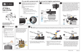
nstalación ...................................................................... 5
In
stalación de la tubería del pozo ............................................5
In
stalación de pozo con caja/cavado .......................................5
In
stalación de puntera .............................................................5
.................................................6
Aplic
ación de aspersión ...........................................................6
In
stalación de la bomba/tubería ..............................................6
A
justes eléctricos ......................................................... 7
C
onexiones del cableado ............................................. 7
O
peración ...................................................................... 8
C
uidado y limpieza ....................................................... 9
R
esolución de fallas ................................................... 10
P
iezas de servicio ....................................................... 11
I
nformación de seguridad
AN
TES DE OPERAR ESTA BOMBA
1. E
vite las quemaduras/explosiones de presión
2. Evite choques eléctricos
Llene la bomba con agua. Asegúrese de que la bomba
esté llena con agua para descargar.
Configuraciones eléctricas del motor: Ajuste el motor
al voltaje adecuado (voltaje suministrado a la bomba).
I
NSTRUCCIONES DE SEGURIDAD
IMPORTANTES
G
UARDE ESTAS INSTRUCCIONES Este manual contiene instrucciones
importantes que deben respetarse durante la instalación, operación
y mantenimiento de esta bomba. También, familiarícese con los
siguientes símbolos de seguridad y sus significados:
PELIGRO: Indica una situación peligrosa que, si no se
evita, resultará en la muerte o lesiones graves.
A
DVERTENCIA: Indica una situación peligrosa que, si
n
o se evita, podría resultar en la muerte o lesiones graves.
P
RECAUCIÓN: Indica una situación peligrosa que, si no
s
e evita, podría resultar en lesiones menores o moderadas.
AV
ISO: Aborda prácticas no relacionadas con lesiones personales.
Lea cuidadosamente y respete todas las instrucciones
de seguridad en este manual y en la bomba.
Mantenga las etiquetas de seguridad en buenas condiciones.
Reemplace las etiquetas de seguridad faltantes o dañadas.
ADVERTENCIA: Riesgo de explosión. El cuerpo de la
bomba puede explotar si se usa como una bomba de carga.
P
RECAUCIÓN: Riesgo de quemaduras. No toque un motor en
f
uncionamiento. Los motores están diseñados para funcionar
a
altas temperaturas. Para evitar quemaduras cuando le
dé servicio a la bomba, deje que enfríe durante 20 minutos
después de apagarla y antes de manipularla.
P
RECAUCIÓN: No deje que la bomba ni ningún componente
s
e congele. Hacerlo así anulará la garantía.
P
RECAUCIÓN: Use esta bomba para bombear
a
gua únicamente.
PRECAUCIÓN: Inspeccione periódicamente la bomba
y los componentes del sistema.
P
RECAUCIÓN: Use gafas de seguridad en todo momento
c
uando trabaje con bombas.
2
LEA Y ENTIENDA ESTE MANUEAL
Tubería del pozo a la bomba ....................................................6
In
stalación de agua superficial
ADVERTENCIA:
No utilice esta bomba para aplicaciones
de refuerzo de presión de agua. La carcasa de la bomba
tiene una capacidad de 55 PSI
MAX.
Gar
antía
E
l fabricante garantiza al comprador consumidor original ("Comprador" o "Usted") de esta bomba que estará libre de defectos en materiales
y mano de obra durante el periodo de la garantía de doce (12) meses a partir de la fecha de compra del consumidor original. Si, dentro de
doce (12) meses a partir de la compra del consumidor original, se comprueba que tal producto está defectuoso, será reparado o reemplazado
a la opción del fabricante, sujeto a los términos y condiciones decritos aquí. Tome nota de que esta garantía limitada aplica a defectos
de fabricación y no al desgaste y uso normales Todos los dispositivos mecánicos necesitan piezas y servicio periódico para que se desempeñen
bien. Esta garantía limitada no cubre la reparación cuando el uso normal ha agotado la vida de una pieza o del equipo.
Para determinar la elegibilidad de la garantía es necesario presentar el recibo de compra original y la etiqueta de información de la garantía.
La elegibilidad está basada en la fecha de compra del producto original y no en la fecha del reemplazo bajo la garantía. La garantía está
limitada a la reparación o reemplazo del producto original comprado únicamente, no al producto de reemplazo (o sea, un reemplazo de garantía
permitido por compra). El comprador paga todos los cargos por retiro, instalación, mano de obra, envío y cargos incidentales.
Para piezas o asistencia de resolución de fallas, NO devuelva el producto a su tienda minorista, póngase en contacto con Servicio al cliente
de Everbilt llamando al 1-844-883-1872.
Los reclamos hechos bajo esta garantía se harán devolviendo el producto (excepto bombas de aguas residuales, ver abajo) a la tienda minorista
donde se compró o a la fábrica inmediatamente después del descubrimiento de cualquier presunto defecto. El fabricante posteriormente
emprenderá acción correctiva tan pronto como sea razonablemente posible. No se aceptarán solicitudes de servicio si se recibe más de 30 días
después de que la garantía expire. La garantía no es transferible y no aplica a productos usados en aplicaciones comerciales/de alquiler.
3 HOM
EDEPOT.COM
P
óngase en contacto con el 1-844-883-1872 para asistencia adicional.
Pr
e-instalación
AN
TES DE INSTALAR ESTA BOMBA
A
DVERTENCIA: Riesgo de explosión. No haga la conexión a tierra a una línea de suministro de gas. El cuerpo de la bomba puede explotar
s
i se usa como una bomba de carga u otra aplicación que no sea la de aspersión.
P
RECAUCIÓN: Riesgo de quemaduras. No toque un motor en funcionamiento. Los motores están diseñados para funcionar a altas
t
emperaturas. Está protegida contra daños por calor durante el funcionamiento mediante un interruptor de corte interno automático. Para
ev
itar quemaduras cuando le dé servicio a la bomba, deje que enfríe durante 20 minutos después de apagarla y antes de manipularla.
L
a entrada de succión de agua de la bomba no debe estar a más de 20 pies sobre el nivel del agua.
Los tendidos largos y muchos accesorios aumentan la fricción y reducen el flujo de agua a la bomba. Ubique la bomba lo más
cerca posible a la fuente de agua. Use la menor cantidad posible de codos y accesorios. Asegúrese de que la línea de succn
esté recta y que se doble hacia la bomba.
Asegúrese de que el pozo y la tubería estén limpios de arena, suciedad y costra. El material extraño taponala bomba y anulará
la garantía. Use tubería nueva para mejores resultados.
Proteja la bombay toda la tubería del congelamiento.
El congelamiento romperá la tubería, dañará la bomba y anulará la garantía. Consulte localmente en busca de requisitos de protección contra
la escarcha. La bomba no se puede instalar abajo de la profundidad de penetración del congelamiento y la bomba debe estar aislada.
Las válvulas de pie o de retención (no incluidas) se deben instalar en la tubería de succión para optimizar la succión de la bomba.
Asegúrese de que todas las tuberías y las válvulas estén limpias y en buen estado.
Asegúrese de que no hayan bolsas de aire en la tubería de succión.
Asegúrese de que no hayan fugas en la tubería de succión. Use cinta Teflón u otro sellador aprobado para sellar las juntas de la tubería.
Las uniones instaladas cerca de la bomba y el pozo ayudarán a darles servicio. Deje espacio para poder usar las llaves.
Pr
e-instalación
DATOS
DE RENDIMIENTO
HP
DI
STANCIA DE LA
S
OBRE EL AGUA
P
RESIÓN DE DESCARGA
10 20 30 40 50
G
ALONES POR MINUTO
1
5
pies 56 45 31 17 --
10 p
ies 49 42 28 12.5 --
15 p
ies 48 39 24 8 --
20 p
ies 45 37 20 -- --
1 1/
2
5 pies 67 61 48 33 --
10 p
ies 61 56 45 26 --
15 p
ies 56 54 44 20 --
20 p
ies 46 44 37 11 --
2
5
pies 83 71 56 41 17
10 p
ies 77 67 54 36 8
15 p
ies 76 65 50 32 --
20 p
ies 75 62 48 28 --
4
236 092 1001
092 1001 238
092 1001 241
S
KU
Salida
1 1/2 in.
Entrada
2 in.
1 1/2 in.
2 in.
2 in.
2 in.
BOMBA
HE
RRAMIENTAS REQUERIDAS (NO INCLUIDAS)
Suction/Tub
ería de
descarga
C
inta selladora
de roscas
Vál
vula
de retención
de 2 pulg.
C
odo
U
nión
Vál
vula
de compuerta
NOT
A: Por favor, seleccione materiales adecuados basados en la entrada y la salida de tamano.
T de cebar
de
2 o 1-1/2 pulg.
de 2 o 1-1/2 pulg.
de 2 o 1-1/2 pulg.
de 2 o 1-1/2 pulg.
de 2 o 1-1/2 pulg.
(recomendado)
Min
Min
Min
Manómetro
Vál
vula
de pie
de
2 pulg.
Vál
vula de alivio
de
presión
(Ver página 4)
2 pulg. NPT
Cesta de filtro
(1/8 pulg.
del agujero)
tamaño
Antes de usar esta bomba, asegúrese de tener los elementos adecuados en función de la téc
nica de la instalación de las páginas siguientes.
IMPORTANTE: No utilice tuberías o accesorios en el lado de succión de la bomba de menos
el rendimiento de cebado.
de 2 pulg.! Esto restringirá succión y reducir la capacidad y el
INSTALACIÓN DE LA TUBERÍA DEL POZO
U
se los métodos de instalación proporcionados en este capítulo que coincidan con su fuente de agua.
I
NSTALACIÓN DE POZO CON CAJA/CAVADO
1. In
speccione la válvula de pie o la válvula de retención
en línea para asegurarse de que funcionen líbremente.
Inspeccione el filtro para asegurarse de que esté limpio
y seguro.
2. Si está usando una válvula de pie, conecte la válvula de pie
y el filtro a la primera sección de la tubería de succión y baje
la tubería al pozo. Agregue secciones de tubería según sea
necesario,usando cinta Teflón en las roscas macho. Use
tubería de 2 pulg. para la tubería de succión. Asegúrese
de que toda la tubería de succión sea a prueba de fugas
o la bomba perderá cebado y dejará de bombear. Instale
la válvula de pie de 10 a 20 pies (3 a 6 m) abajo de nivel
más bajo al cual el agua caerá mientras la bomba está
funcionando (nivel de agua de bombeo). Su perforador
de pozo le puede proporcionar esta información.
3. Para evitar que la arena y sedimentos ingresen al sistema
de bombeo, una válvula de pie/filtro debe estar al menos
a 5 pies (1.5 m) sobre el fondo del pozo.
4. Cuando se logra el nivel apropiado, instale un sello de pozo
sanitario sobre la tubería y en la caja del pozo. Apriete todos
los pernos en la caja del pozo.
5. Cuando use una válvula de pie, se recomienda una T y tapón
de cebado.
5 HOM
EDEPOT.COM
P
óngase en contacto con el 1-844-883-1872 para asistencia adicional.
I
nstalación
AVISO: Se recomienda que la bomba se instale en el recinto bien ventilado.
I
NSTALACIÓN DE PUNTERA
1. C
onecte la tubería de succión en la puntera. Mantenga el
tendido de la tubería horizontal lo más corto posible. Use
cinta Teflón en las roscas macho de la tubería. Es posible
que sean necesarios múltiples puntos de pozo para brindar
agua suficiente a la bomba.
2. Instale una válvula de retención en la tubería horizontal.
La flecha de flujo en la válvula de retencn debe apuntar
hacia la bomba.
A
cabezas
del aspersor
A cabezas
del aspersor
Cabezas múltiples
de pozo
Válvula de
retención
Instalación del punto impulsado,
puntos múltiples de pozo
Tu
bería de descarga
Válvula de compuerta
I
nstalación (continuación)
TU
BERÍA DEL POZO A LA BOMBA
E
l rendimiento de la bomba disminuirá si el diámetro de la tubería
es menor que el tamaño de la entrada de la bomba. Si la instalación
es adecuada, el tamaño de la tubería es igual al tamaño de la entrada.
Para agregar cebado en instalaciones de punto de pozo, instale una
válvula de retención de línea. Asegúrese de que la flecha de flujo de
la válvula de retención apunte hacia la bomba.
El tamaño de la tubería de la bomba a la tubería de descarga de los
cabezales del rociador se debe aumentar para reducir las pérdidas
de presión causadas por la fricción en tendidos largos de tubería:
Tendido de hasta 100 pies (30.5 m): Igual tamaño que el
puerto de descarga de la bomba.
Tendido de 100 pies a 300 pies (30.5 a 91.4 m): Aumentar
un tamaño de tubería.
Tendido de 300 pies a 600 pies (91.4 a 182.9 m): Aumentar
dos tamaños de tubería.
I
NSTALACIÓN DE LA BOMBA/TUBERÍA
S
i se está apagando y encendiendo la bomba por presión, se necesita
un interruptor de presión y tanque. Para una instalación e instrucciones
de operación adecuadas, llame a Servicio al cliente
Use tubería rígida. No use manguera ni tubería plástica. Consulte
“Instalación de tubería de pozo” para obtener más información.
Use solo cinta selladora de rosca de tubería PTFE para compuestos
de junta para hacer todas las conexiones roscadas a la bomba misma.
No use compuestos de junta de tubería en bombas plásticas ya que
pueden reaccionar con el plástico en los componentes de la bomba.
Asegúrese de que todas las juntas de la tubería en la tubería de succión
sean a prueba de aire así como a prueba de agua. Si la tubería de succión
la bomba no va a poder sacar agua del pozo.
1. Emperne la bomba en una base sólida y a nivel.
2.
Soporte toda la tubería conectada a la bomba.
3. Coloque de 1-1/2 a 2 capas de cinta Teflón hacia la derecha
(teniendo enfrente suyo el extremo de la tubería) en todas
las roscas macho unidas a la bomba.
4. Apriete a mano las juntas más de 1-1/2 vueltas.
No apriete demasiado.
5. Reemplace el tapón de cebado por un manómetro. Esto
ayudará a dimensionar zonas, a resolver fallas y a seguir
la tabla de rendimiento de la bomba.
N
OTA: Para tendidos largos de tubería horizontal, instale
u
na T de cebado entre la válvula de retención y la boca del
po
zo, Consulte la figura en la sección Instalación de pozo
c
on caja/cavado para referencia adicional.
6
APLI
CACIÓN DE ASPERSIÓN
fuente de pozo.
Vertical del agua superficial a la bomba
1.
2.
Horizontal del agua superficial a la bomba
Cesta de filtro
E
adecuadamente, entregará agua y presión adecuadas
USE NUEVO TUBO PARA
MEJORES RESULTADOS
TUBO DE BOMBA A APLICACION DE USO FINAL
AGUA SUPERFICIAL
    
  
I
NSTALACIóN DE

 
 
Vál
vula
de retención
Vál
vula de pie
con colador
tiene algún fuga,
sta bomba está diseñada para sistema de irrigacion del cesped.
Cuando está instalada
de cualquier
Válvula de pie con filtro (1/8 pulg. tamaño del agujero)
unido al tubo de PVC.
Colador (1/8 pulg. tamaño del agujero) y / o cesta
de co lador instalada en el extrem
o del tubo de
PVC.
aspiración de
Instale la válvula de retención en la tubería de
PVC cerca de la bomba.
fabricante del
interruptor.
de depósito y / o
(1/8 pulg. tamaño del agujero)
A
justes eléctricos
A
DVERTENCIA: Desconecte la energía antes de trabajar en la bomba, el motor, el interruptor de presión o el cableado.
P
RECAUCIÓN: El motor puede estar caliente. Deje que el motor se enfríe durante 20 minutos después de apagarlo.
P
RECAUCIÓN: La presión del agua se puede acumular en la bomba, tuberías o el tanque. Drene el agua para liberar la presión.
C
onexiones del cableado
A
DVERTENCIA: Riesgo de choque eléctrico. Puede dar un choque, quemar o matar.
1. P
ara evitar choques eléctricos peligrosos o fatales, apague la energía al motor antes de trabajar en las conexiones eléctricas.
2. C
onecte a a tierra el motor antes de conectar a la fuente de alimentación eléctrica. No conectar a tierra el motor
p
uede causar peligro de choques eléctricos severos o fatales.
3. E
l voltaje de alimentación debe estar dentro de +/- 10% del voltaje de la placa de identificación. El voltaje incorrecto puede
o
casionar un incendio o dar el motor y anular la garantía. Si tiene dudas, consulte con un electricista calificado.
4. U
se un tamaño de cable especificado en la Tabla de cableado (abajo). Si es posible, conecte la bomba a un circuito
d
e derivación aparte sin ningún otro aparato en él.
5. N
o haga la conexión a tierra a una línea de suministro de gas.
6. H
aga el cableado del motor de acuerdo al diagrama en la placa de identificación del motor.
7. Si e
l diagrama de la placa de identificación difiere de los diagramas en esta sección, siga el diagrama de la placa
d
e identificación.
8. S
i este procedimiento o los diagramas de cableado le resultan confusos, consulte con un electricista calificado.
7 HOM
EDEPOT.COM
P
óngase en contacto con el 1-844-883-1872 para asistencia adicional.
Torn
illos de
la placa
Cubierta del
motor
 
AJUSTES DE VOLTAJE DE MOTOR
L
Los motores están diseñados para funcionar con 115 volt
ios o 230 voltios.
tensión suministrada por el motor de la fuente eléctrica.
Para configurar el motor a la tensión correcta, primero retire la placa
de c
onversión de tensión a la tensión correcta.
Compruebe que la tensión del motor
se ajusta para que coincida con la
de la cubierta trasera del motor. A
continuación deslice el interruptor
Fijado para 115V
115
Al interruptor
automático
Vivo
Neutro
Al interruptor
automático
Al interruptor
automático
Al interruptor
automático
Vivo
Vivo
L1
L2
230
L1
L2
Fijado para 230V
ó
Ope
ración
ADVERTENCIA: Presión peligrosa. Instale una válvula de alivio de presión en la tubería de descarga. Libere toda la presión en el sistema
an
tes de trabajar en cualquier componente.
A
DVERTENCIA: Riesgo de explosión y quemaduras. NUNCA
po
nga a funcionar la bomba contra una descarga cerrada.
Si lo hace, puede hacer que hierva el agua dentro de la bomba,
causando presión peligrosa en la unidad, riesgo de explosión
y
posiblemente quemaduras a las personas que manejan
l
a bomba. Reemplace el tapón de cebado por un manómetro
p
ara monitorear la presión de modo que no se permita que
s
upere las presiones máximas de bombeo de acuerdo a la
tabla de rendimiento.
P
ara evitar una explosión, asegúrese de que la descarga (válvula,
empuñadura de la pistola, boquilla de la manguera, etc.) esté abierta
siempre que esté funcionando la bomba. Monitoree la temperatura
del cuerpo de la bomba y de la tubería. El motor se calentará, esto
es normal. Si el cuerpo de la bomba o la tubería comienzan a sentirse
calientes al tacto, apague la bomba y deje que se enfríe el sistema.
Libere toda la presión en el sistema y rellene la bomba y la tubería
con agua fría.
C
EBADO DE LA BOMBA
E
l cebado se refiere a expulsar todo el aire en el sistema y comenzar a mover agua de su fuente al sistema. No se refiere únicamente a vertir
agua a la bomba (aunque vertir agua generalmente es el primer paso).
PRECAUCIÓN: Riesgo de quemaduras. NUNCA ponga a funcionar la bomba en seco. Poner a funcionar la bomba sin agua puede hacer que
la bomba se sobrecaliente, dañando el sello y posiblemente causando quemaduras a las personas que manipulan la bomba. Llene la bomba
c
on agua antes de arrancarla.
1. R
etire el tapón de cebado.
2. Asegúrese de que estén abiertas las válvulas de succión y de descarga
mba.
3.
Llene la bomba y la tubería de succión con agua.
4. Vuelva colocar el tapón de cebado usando cinta Teflón en las roscas. Apriete el tapón. Si se han proporcionado T y tapón de cebado
para el tendido largo horizontal, llene la tubería de succión a través de esta T y vuelva a colocar el tapón. (Use cinta Teflón en el tapón.)
5. Arranque la bomba. Se debe producir agua en 10 minutos o menos. El tiempo depende de la profundidad del agua (no más de 20 pies
(6 m)) y la longitud del tendido horizontal (10 pies (3 m) de la tubería de succión horizontal = 1 pie (30 cm) de levantamiento vertical
debido a pérdidas por fricción en la tubería). Si no se produce agua en 10 minutos, pare la bomba, libere toda la presión, retire el
tapón de cebado, vuelva a llenar e intente de nuevo.
8
y cualquier manguera en el lado de la descarga de la bo
TAM
AÑOS RECOMENDADOS DE CABLE Y FUSIBLE PARA 115 Y 230 VOLTIOS
HP
DEL
M
OTOR
V
OLTIOS
X. AMP.
DE
CARGA
FU
SIBLE DE
DE
RIVACIÓN
A
MP.
A
WG MÍN.
T
AMAÑO DE
C
ABLE (mm
2
)
DI
STANCIA EN PIES DEL MOTOR A LA FUENTE
0-100 101-200 201-300 301-400 401-500
T
AMAÑO DE CABLE AWG (mm
2
)
1 10/14 (5.5/2) 8/14 (2/2) 6/14 (14
/
2) 6/12 (14/3) 4/10 (21/5.5)
30/15
10/14 (5.5/2) 10/14 (5.5/2) 8/14 (8.4/2) 6/12 (14/3) 4/10 (21/5.5) 4/10 (21/5.5)
2
1
15/230
27
.0/13.5
35
/20
8/12
4/10 (21/5.5) 4/10 (21/5.5)
1-1/2
115/230 22/11
8/12 (8.9/3) 8/12 (8.4/3) 6/10 (14/5.5)
115/230 18.5/9.25 30/15 10/14 (5.5/2)
(8.9/3)
  • Page 1 1
  • Page 2 2
  • Page 3 3
  • Page 4 4
  • Page 5 5
  • Page 6 6
  • Page 7 7
  • Page 8 8
  • Page 9 9
  • Page 10 10
  • Page 11 11
  • Page 12 12
  • Page 13 13
  • Page 14 14
  • Page 15 15
  • Page 16 16
  • Page 17 17
  • Page 18 18
  • Page 19 19
  • Page 20 20
  • Page 21 21
  • Page 22 22
  • Page 23 23
  • Page 24 24

Everbilt EFLS20-HD Operating instructions

Type
Operating instructions

Everbilt EFLS20-HD is a powerful 2 HP plastic lawn sprinkler pump designed for efficient and reliable water distribution in residential irrigation systems. With a maximum flow rate of 83 gallons per minute and a discharge pressure of up to 56 PSI, it can effortlessly handle the demands of large lawns and gardens. Its durable construction and simple operation make it an ideal choice for homeowners seeking a dependable watering solution.

Ask a question and I''ll find the answer in the document

Finding information in a document is now easier with AI

in other languages