Page is loading ...

R
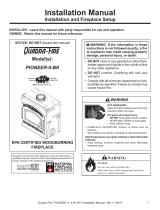
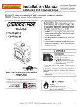
EPA CERTIFIED WOODBURNING
FIREPLACE
Model(s):
Installation Manual
Installation and Fireplace Setup
WARNING
HOT SURFACES!
Glass and other surfaces are hot during
operation AND cool down.
Hot glass will cause burns.
• DO NOT touch glass until it is cooled
• NEVER allow children to touch glass
• Keep children away
• CAREFULLY SUPERVISE children in same room as
replace.
• Alert children and adults to hazards of high temperatures.
High temperatures may ignite clothing or other ammable
materials.
• Keep clothing, furniture, draperies and other ammable
materials away.
INSTALLER: Leave this manual with party responsible for use and operation.
OWNER: Retain this manual for future reference.
PIONEER-III-ABK
PIONEER-III-RBK
Pour demander un exemplaire
en français de ce Manuel
du propriétaire, visitez www.
quadrare.com/translations.
Installation andservice of this appliance should be performed by
qualied personnel, Hearth & Home Technologies recommends
HHTFactoryTrainedorNFIcertiedprofessionals.
Contact your dealer with questions on installation, operation, or service.
• Read all the instructions before starting
the installation. Follow these instructions
carefully during the installation to ensure
maximumsafetyandbenet.
• Comply with all minimum clearances to com-
bustiblesasspecied.Failuretocomplymay
causehousere.
WARNING! Risk of Fire and/or Asphyxiation!
1
Quadra-Fire • PIONEER - III • 4182-901 Installation Manual • Rev E • 10/19

Safety Alert Key:
• DANGER! Indicates a hazardous situation which, if not avoided will result in death or serious injury.
• WARNING! Indicates a hazardous situation which, if not avoided could result in death or serious injury.
• CAUTION! Indicates a hazardous situation which, if not avoided, could result in minor or moderate injury.
• NOTICE:Indicatespracticeswhichmaycausedamagetothereplaceortoproperty.
Table of Contents
1 Product Specic & Important Safety Information
A.ApplianceCertication 4
B.BTUEciencySpecications 4
C.MobileHomeApproved 4
D.GlassSpecications 5
E.Non-CombustibleMaterials 5
F.CombustibleMaterials 5
G.ElectricalCodes 5
2 Getting Started
A.TypicalFireplaceSystem 6
B. Design and Installation Considerations 7
1. Selecting Fireplace Locations 7
2.LocatingFireplace&Chimney 8
C.ToolsandSuppliesNeeded 9
D.InspectFireplaceandComponents 9
E.FireplaceSystemRequirements 9
3 Framing and Clearances
A. Fireplace Dimensions 10
B. Clearances 11
C. Construct the Chase 12
D. Frame the Fireplace 13
E. Secure and Level the Fireplace 13
F. InstallationofTopStandos 14
G.ProtectiveMetalHearthStrips 15
H.Non-CombustibleFacingBoard(Provided) 15
I. OutsideAirKit 15
J.FanAirKit(Required) 18
K.HeatZoneKit(Optional) 19
4 Electrical Wiring
A. Fireplace 23
B.ThermostatInstallation 23
5 Chimney and Termination Requirements
A.ChimneyRequirements 25
B.Osets/Returns 26
C.TerminationRequirements 27
6 Chimney Installation
A.TypicalChimneySystem 28
B.AssembleChimneySections 29
C.InstallChimneyAirKit(CAK4A) 29
D.SecureOset/Return 30
E. Install Ceiling Firestops 31
F. Install Attic Insulation Shield 32
G. Roof Penetration 33
H.ManufacturedHomeInstallation 33
I. InstallChase/ChaseTop 34
J. InstallTerminationCap 35
7 Finishing
A.Template 37
B.FinishtheWall 38
1.Stone,BrickFinish 38
2.Tile,Granite,MarbleFinish 38
C.MantelandWallProjections 38
D.FinishingtheHearthExtension 39
E.Non-CombustibleSealantMaterial 40
8 Fireplace Setup
A.FirebrickPlacement 41
B.BaeandBlanketPlacement 42
C.InstallFascia(Fronts) 42
9 Reference Materials
A.ChimneyComponents 43
B.Accessories 48
2
Quadra-Fire • PIONEER - III • 4182-901 Installation Manual • Rev E • 10/19
►

Customer:
Lot/Address
Model: PIONEER III-ABK
PIONEER III-RBK
YES IF NO, WHY?Fireplace Install
Verified that the chase is insulated and sealed.
Requirednon-combustibleboardisinstalled.
Verifiedclearancestocombustibles.
Fireplace is leveled and secured.
Hearthextensionsize/heightdecided.
Outside air kit installed.
OptionalHeatZonehasbeeninstalledbyaqualifiedservicetechnician.
Fan air kit installed.
Chimney Section 5
Chimney configuration complies with diagrams.
Chimney installed, locked and secured in place with proper clearance.
Chimney air kit installed.
Firestops installed.
Attic insulation shields installed.
Roof flashing installed and sealed.
Terminationsinstalledandsealed.
Electrical Section 4
Switch wires properly installed.
Thermostat wires connected.
Dealer/Distributor Phone #
Serial #:
WARNING! Risk of Fire or Explosion! Failure to install fireplace acording to these instructions can lead to a fire or
explosion.
ATTENTION INSTALLER:
Follow this Standard Work Checklist
Thisstandardworkchecklististobeusedbytheinstallerinconjuctionwith,notinsteadof,theinstructionscontainedinthisinstallation
manual.
Date Installed:
Location of Fireplace:
Installer:
Finishing Section 7
CombustibleCombustiblematerialsmaterialsnotnotinstalledinstalledininnon-non-combustiblecombustibleareasareas.
Verified all clearances meet installation manual requirements.
Mantels and wall projections comply with installation manual requirements.
Protective hearth strips and hearth extension installed per manual requirements.
Fireplace Setup Section 8
All packaging and protective materials removed.
Firebrick,baffleandceramicblanketinstalledcorrectly.
Facia and doors properly installed.
Manualbagandallofitscontentsareremovedfrominside/underthefireplaceand
giventothepartyresponsibleforuseandoperation.
Allpackagingmaterialsareremovedfrominside/underthefireplace.
Hearth & Home Technologies recommends the following:
•
Photographing the installation and copying this checklist for your file.
•
Thatthischecklistremainvisibleatalltimesonthefireplaceuntiltheinstallationiscomplete.
Commentscommunicatedtopartyresponsible
Part # 4182-982 • Rev A • 06/18
__________________________by______________________on_________
(Builder/Gen.Contractor)(Installer)(Date)
Comments:Furtherdescriptionoftheissues,whoisresponsible(Installer/Builder/OtherTrades,etc.)andcorrectiveactionneeded:
_________________________________________________________________________________________________
________________________________________________________________________________________________________
________________________________________________________________________________________________________
3
Quadra-Fire • PIONEER - III • 4182-901 Installation Manual • Rev E • 10/19

1
Product Specic & Important Safety Information
Model:
PIONEER III
Laboratory: Underwriter’sLaboratories,Inc.
Report No:
Project4788732172
Type:
Wood Fireplace
Standard: UL127-2011andCAN/ULC-S610-
2018(A1998)and(UM)84-HUD,
ManufacturedHomeApproved.
A. Appliance Certication
C. Mobile Home Approved
Thisapplianceisapprovedformobilehomeinstallations
when not installed in a sleeping room and when an outside
combustionairinletisprovided.Thestructuralintegrityof
the mobile homeoor, ceiling, and walls must be main-
tained.Theappliancemustbeproperlygroundedtothe
frameofthemobilehomeanduseonlylisteddouble-wall
connector pipe.
D. Glass Specications
Thisapplianceisequippedwith5mmceramicglass.
Replaceglassonlywith5mmceramicglass.Please
contact your dealer for replacement glass.
B. BTU & Eciency Specications
Hearth & HomeTechnologies WILLNOT warranty appli-
ances that exhibit evidence of over-ring. Evidence of
over-ringincludes,butisnotlimitedto:
• Warpedairtube
• Deterioratedrefractorybrickretainers
• Deterioratedbaeandotherinteriorcomponents
NOTE: Thisinstallationmustconformwithlocalcodes.Inthe
absenceoflocalcodesyoumustcomplywiththeUL127-2011,
(UM) 84-HUD and NPFA211 intheU.S.A.andtheCAN/ULC
S610-2018 (A1998) and CAN/CSA-B365 Installation Codes
in Canada.
ThePIONEERIIIWoodAppliancemeetstheU.S.ENVI-
RONMENTALPROTECTIONAGENCYCertiedtocomply
with 2020 particulate emission standards using cord wood.
EPACertiedEmissions: 2.0g/hr
*LHVTestedEciency: 74.3%
**HHVTestedEciency: 69.1%
***EPABTUOutput: 14,700-72,800/hr
VentSize: 8inches
FireboxSize: 4.07cubicfeet
RecommendedLogLength: 24inches
Fuel Seasoned Cord Wood less
than20%moisture
HHT: SL300 Series
DuraVent: DuraPlus
*WeightedaverageLHV(LowHeatingValue)eciencyusing
cordwoodanddatacollectedduringEPAemissiontest.LHV
assumes the moisture is already in a vapor state so there is no
loss in energy to vaporize.
**WeightedaverageHHV(HighHeatingValue)eciencyus-
ing cord wood and data collected during EPA emission test.
HHVincludestheenergyrequiredtovaporizethewaterinthe
fuel.
***ArangeofBTUoutputsbasedonHHV(HighHeatingValue)
andtheburnratesfromthelowandhighEPAtests,usingcord
wood.
The Pioneer III is Certied to
comply with 2020 particulate
emission standards.
DO NOT:
• installoroperatedamagedreplace
• modifyreplace
• install other than as instructed by Hearth & Home
Technologies
• operate the fireplace without fully assembling all
components
• install unvented gas log set
• install any component not approved by Hearth & Home
Technologies
• install parts or components not Listed or approved
Improper installation, adjustment, alteration, service or
maintenance can cause injury or property damage. For
assistance or additional information, consult a qualied
installer, service agency or your dealer.
WARNING! Risk of Fire! Hearth & Home Technologies
disclaims any responsibility for, and the warranty and
agency listing will be voided by the above actions.
4
Quadra-Fire • PIONEER - III • 4182-901 Installation Manual • Rev E • 10/19

G. Electrical Codes
NOTICE: This replace must be electrically wired and
grounded in accordance with local codes or, in the
absence of local codes, with National Electric Code ANSI/
NFPA 70-latest edition or the Canadian Electric Code
CSA C22.1.
• A110-120VACcircuitforthisproductmustbeprotected
with ground-fault circuit-interrupter protection, in
compliancewiththeapplicableelectricalcodes,when
it is installed in damp locations.
WARNING! Improper installation, adjustment, alteration,
service or maintenance can cause injury or property dam-
age.
E. Non-Combustible Materials
Materialwhichwillnotigniteandburn,composedofany
combinationofthefollowing:
- Steel - Plaster
- Brick - Iron
-Concrete -Tile
- Glass - Slate
Materials reported as passing ASTM E 136, Standard
Test Method for Behavior of Metals, in a Vertical Tube
Furnace of 750° C.
F. Combustible Materials
Material made of or surfaced with any of the following
materials:
- Wood - Compressed Paper
-PlantFibers -Plastic
-Plywood/OSB -SheetRock(drywall)
-Foaminsulation&sealants
Anymaterialthatcanigniteandburn:ameproofedor
not, plastered or un-plastered.
5
Quadra-Fire • PIONEER - III • 4182-901 Installation Manual • Rev E • 10/19

2
Getting Started
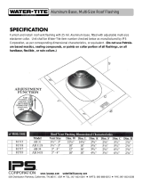
Termination Cap
Chimney penetrates roof
preferably without affecting
roof rafters
Offset/Return
(with hanger straps)
Attic insulation shield
must be used to keep
insulation away
from chimney if
attic is insulated
Storm Collar
Framing headed
off in ceiling joists
Mantel
Chimney system
Combustible
framing/header
Non-combustible material
Hearth extension
Non-combustible
roof flashing maintains
minimum clearance
around chimney
Additional lateral
support for chimney
above roof (or enclosed
in chase) if needed
Enclosed space above
and around fireplace
Ceiling firestop
on floor of attic
Support straps
on rafter supports
chimney (not shown)
Outside
combustion air
Outside
combustion air
Chimney Air Kit (CAK-4A) (not
shown) must be used with SL300
chimney
Protective metal
hearth strip(s)
Figure 2.1 Typical Fireplace System
6
Quadra-Fire • PIONEER - III • 4182-901 Installation Manual • Rev E • 10/19

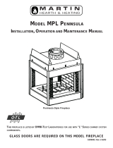
Figure 2.2 Fireplace Locations
NOTICE:
• Illustrationsandphotosreecttypicalinstallationsand
are FOR DESIGN PURPOSES ONLY.
• Illustrations/diagrams are not drawn to scale.
• Actual installation/appearance may vary due to individual
design preference.
• Hearth & Home Technologies reserves the right to alter
its products.
NOTICE: In addition to these framing dimensions, also
reference the following section:
• Clearances (Section 3).
NOTICE:
A minimum 1 in. air clearance at the back and a
minimum 1½ in. air clearance to the sides of the
replaceassemblymustbemaintained.
Chimney sections at any level require a 2 in. mini-
mum air space clearance between the framing and
chimney sections.
B. Design and Installation Considerations
NOTICE: Check building codes prior to installation.
• InstallationMUSTcomplywithlocal,regional,stateand
national codes and regulations.
• Consultinsurancecarrier,localbuildinginspector,re
ocialsorauthoritieshavingjurisdictionoverrestrictions,
installation inspection and permits.
1. Selecting Fireplace Locations
This replace may be used as a room divider, installed
along a wall, across a corner or used in an exterior chase.
See Figure 2.2.
Locating the replace in a basement, near frequently
opened doors, central heat outlets or returns, or other loca-
tionsofconsiderable airmovementcanaecttheperfor-
mance.
Outsideairmust beusedforcombustion.ThePIONEER
III comes equipped with an outside air inlet to feed com-
bustionairfromoutsidethehome,alongwithanoutsideair
terminationcap;themetalductisrequiredbutnotsupplied.
Considerationshouldbegiventothesefactorsbeforede-
ciding on a location.
24-1/2*
[622]
51 [1295]
16 [406]
51 [1295]
[1562]
16 [406]
24-1/2*
[622]
24-1/2*
[622]
51
[1295]
16
[406]
48 [1219]
103
[2616]
51
[1295]
73 [1854]
51-1/2
[1308]
27-1/2
[699]
27-1/2
[699]
Across a corner
In an exterior chase
As a divider
Along a wall
*If interior of chase will be
drywalled, add the thickness
to this measurement.
Faceplate to sidewall 16 inches
61-1/2
[1562]
61-1/2
[1562]61-1/2
7
Quadra-Fire • PIONEER - III • 4182-901 Installation Manual • Rev E • 10/19

2. Locating Fireplace & Chimney
Locationofthereplaceandchimneywillaectperfor-
mance.
• Installwithinthewarmairspaceenclosedbythebuilding
envelope.Thishelpstoproducemoredraft,especially
duringlightinganddie-downofthere.
• Penetratethehighestpartoftheroof.Thisminimizes
theeectsofwindloading.
• Locate termination cap away from trees, adjacent
structures,unevenrooflinesandotherobstructions.
• Minimizetheuseofchimneyosets.
• Considerthereplacelocationrelativetooorandceiling
and attic joists.
• Takeintoconsiderationtheterminationrequirementsin
Sections5and6.
Marginal Location:
• Below peak
Location NOT recommended:
• Not the highest point of the roof
• Wind loading possible
Multi-level Roofs
Windward
Leeward
Recommended Location:
• Above peak
Recommended:
• Insulated exterior chase
in cooler climates
Recommended Location:
• Above peak
• Inside heated space
Location NOT recommended:
• Too close to tree
• Below adjacent structure
• Lower roof line
• Avoid outside wall
Marginal Location:
• Wind loading possible
Not recommended in basement due
to high negative pressure concerns
that effect draft
Figure 2.3 Recommended Chimney Locations
• InstalltheoutsideairkitandCAK(chimneyairkit)with
the intake facing prevailing winds during the heating
season.
• Ensure adequate outdoor air for all combustion
appliances and exhaust equipment.
• Ensure furnace and air conditioning return vents are not
locatedintheimmediatevicinityofthereplace.
• Avoidinstallingthereplaceneardoors,walkwaysor
small isolated spaces.
• Recessedlightingshouldbea“sealedcan”design.
• Attic hatches weather stripped or sealed.
• Attic mounted duct work and air handler joints and seams
taped or sealed.
8
Quadra-Fire • PIONEER - III • 4182-901 Installation Manual • Rev E • 10/19

C. Tools and Supplies Needed
Beforebeginningtheinstallationbesurethefollowing
toolsandbuildingsuppliesareavailable:
Reciprocating saw Framing material
Pliers Non-combustiblesealant
Hammer Gloves
Phillips screwdriver Framing square
Flatbladescrewdriver Electricdrillandbits
Plumbline Safetyglasses
Level Tapemeasure
1/2-3/4in.length,#6or#8self-drillingscrews
Misc. screws and nails
D. Inspect Fireplace and Components
E. Fireplace System Requirements
TheQuadra-Firereplacesystemrequirementsconsistof
thefollowing:
• Fireplace
- Firebrick(includedwithreplace)
- Door(includedwithreplace)
- Non-combustible facing material (included with
replace)
- HearthExtension
• OutsideAir System (hood and collars included with
replace)
• Fascia
• Chimney System
- CAK4A Chimney air kit (included with fireplace,
requiredwithSL300serieschimney)
- AtticInsulationShield(includedwithreplace)
- Chimney termination cap
• Non-combustiblenishmaterial
• FanAirSystem(grillandcollarincludedwithreplace)
Optionalcomponentsinclude:
• Lintel Bar
• Heat-Zone-WDKit
• WirelessThermostat
WARNING! Risk of Fire and Asphyxiation! Damaged
parts could impair safe operation. DO NOT install dam-
aged, incomplete or substitute components.
• Removereplaceandcomponentsfrompackagingand
inspect for damage.
• Chimney system components and other optional
components are shipped separately.
• Report to your dealer any parts damaged in shipment.
9
Quadra-Fire • PIONEER - III • 4182-901 Installation Manual • Rev E • 10/19

3
Framing and Clearances
A. Fireplace Dimensions
Figure 3.1 Fireplace Dimensions
1 in.
(25 mm)
23 ½ in.
(597 mm)
12 ¾ in.
(324 mm)
16 in.
(406 mm)
63 ¼ in.
(1607 mm)
39 in.
(991 mm)
47 ¼ in.
(1200 mm)
5 -7/8 in.
(149 mm)
1 ½ in.
(38 mm)
28-1/8 in.
(714 mm)
39 in.
(991 mm)
47-7/8 in.
(1216 mm)
50-7/8 in.
(1292 mm)
19-1/8 in.
(486 mm)
15 in.
(381mm)
1½ in.
(38 mm)
1 in.
(25 mm)
9 ¾ in.
(248 mm)
17 ¼ in.
(428 mm)
8 ¼ in.
(210 mm)
6½ in.
(165 mm)
1 in.
(25 mm)
23 ½ in.
(597 mm)
12 ¾ in.
(324 mm)
16 in.
(406 mm)
63 ¼ in.
(1607 mm)
36 ½ in.
(927 mm)
47 ¼ in.
(1200 mm)
5 -7/8 in.
(149 mm)
1 ½ in.
(38 mm)
28-1/8 in.
(714 mm)
39 in.
(991 mm)
47-7/8 in.
(1216 mm)
50-7/8 in.
(1292 mm)
15 in.
(381mm)
1½ in.
(38 mm)
18-1/8 in.
(460 mm)
1 in.
(25 mm)
9 ¾ in.
(248 mm)
17 ¼ in.
(428 mm)
8 ¼ in.
(210 mm)
6½ in.
(165 mm)
10
Quadra-Fire • PIONEER - III • 4182-901 Installation Manual • Rev E • 10/19

B. Clearances
WARNING! Risk of Fire!
You must comply with all minimum air space clearances
tocombustiblesasspeciedinFigure3.2.DO NOT pack
required air spaces with insulation or other materials.
Framing or nishing material used on the front of, or in
frontof,thereplacecloserthantheminimumslistedmust
be constructed entirely of non-combustible materials (i.e.,
steel studs, concrete board, etc.). Failure to comply may
causere.
Figure 3.2 Clearances to Combustible Materials
(ceiling)
(roof)
(ceiling)
2 in. (51 mm) min.
Attic
Insulation
Shield
Ceiling Firestop
(attic)
Storm Collar
Roof Flashing
2 in. min.
(51 mm)
2 in. (51 mm) min.
2 in. (51 mm) min.
Ceiling Firestop
Offset/Return with
hanger straps
2 in.
(51 mm)
min.
2 in. (51 mm) min.
Must have 2 in. (51 mm)
minimum clearance
to header
Electrical wires must be a minimum of
16 in. (406 mm) from top
1-1/2 in. (38 mm) to side of appliance
1 in. (25 mm) to back
of appliance
0 in.
to floor
36 in. (914 mm)
Top of appliance to
ceiling
Chimney Air Kit required with SL chimney
DuraPlus base plate required with Duraplus chimney
WITHIN ENCLOSURE AREA
Fireplacetobackwall 1in.(25mm)
Fireplace to sidewall 1½in.(38mm)
Ductbootstoframing 0in.(0mm)
Topofreplacetoheader 16in.(406mm)
Door opening to sidewall 22-3/4in.(578mm)
EXPOSED SURFACES
Faceplate to sidewall 16in.(406mm)
Heatzoneairgrillstoceiling 12in.(305mm)
MANTEL
Non-combustiblemantel
(Non-combustibleframing
materialsabovethereplace
toceiling)
46in.(1168mm)
fromthebaseofthe
replaceup
Combustiblemantel
(Combustibleframing
materialsabovethereplace
toceiling)
66in.(1676mm)
fromthebaseofthe
replaceup
Maximum mantel depth 12in.(305mm)
11
Quadra-Fire • PIONEER - III • 4182-901 Installation Manual • Rev E • 10/19

Ceiling
Firestop
Metal Chase Top
Round Termination Cap
False Ceiling
Insulation in the
outside walls
of the chase
Attic
Insulation
Shield
Chimney
Ceiling
Firestop
Tabs
False Ceiling
False Ceiling
Insulation
Insulation
Storm Collar
Figure 3.3 Chase Assembly
1 2 3
All outside walls should be insulated.
Figure 3.4 Chase Constructions
1. Fireplace and chimney enclosed in an exterior chase.
2. Chimneyosetthroughexteriorwallandenclosedinchase.
3. Chase constructed on roof.
• Thechaseisconstructedusingframingmaterialsmuch
the same as the walls in your home. A variety of siding
materials may be used including brick, stone, veneer
brick,orstandardsidingmaterials.
• In constructing the chase, several factors must be
considered:
- Maintain a 2 in. (51 mm) air space around the
chimney.
- The chase top must be constructed of non-
combustiblematerial.
- Incoldclimates,arestopspacerandatticinsulation
shieldshouldbeinstalledinaninsulatedfalseceiling
at the 8 ft. (2438 mm) level above the replace
assembly.Thisreducesheatlossthroughthechase.
- In cold climates,thewalls of thechase should be
insulated to the level of the false ceiling as shown in
Figure3.4.Thiswillhelpreduceheatlossfromthe
homearoundthereplace.
ThreeexamplesofchaseapplicationsareshowninFig-
ure3.4.
C. Construct the Chase
Achaseisaverticalboxlikestructurebuilttoenclosethe
replace and/or its vent system. Vertical chimneys that
runontheoutsideofabuildingmustbeinstalledinsidea
chase.SeeFigure3.4.
Constructionofthechasemayvarywiththetypeofbuild-
ing.LocalbuildingcodesMUSTbefollowed.
Hearth&HomeTechnologiesrecommends:
- The inside surfaces be drywalled and taped (or
theuseofanequivalentmethod)formaximumair
tightness to the false ceiling.
- In cold climates, the walls ofthechase should be
insulated to the level of the false ceiling as shown in
Figure3.3.Thiswillhelpreduceheatlossfromthe
homearoundthereplace.
- Holes and other openings should be caulked with
hightemperaturecaulkorstuedwithunfacedber
glass insulation.
• Requirementsforconstructingthechase:
- Arestopspacerandatticinsulationshieldshould
beinstalledatthefalseceiling.
- Thechasemustbeproperlyblockedtopreventblown
insulationorothercombustiblesfromenteringand
makingcontactwithreplaceorchimney.
- The chase top must be constructed of non-
combustiblematerial.
WARNING! Risk of Fire! DO NOT sealareabetweenre
stop opening and chimney pipe except where they enter
the attic or leave the warm air envelope of the home (use
600° F sealant).
WARNING! Risk of Fire! You must maintain a minimum 2
in. (51 mm) air space clearance to insulation and framing
surrounding the chimney system.
12
Quadra-Fire • PIONEER - III • 4182-901 Installation Manual • Rev E • 10/19

D. Frame the Fireplace
WARNING! Risk of Fire! You must comply with all mini-
mum air space clearances to combustibles. DO NOT pack
required air spaces with insulation or other materials.
WARNING! Risk of Fire! Comply with all minimum clear-
ancesspecied.
• A minimum 1 in. (25 mm) air clearance must be
maintained at the back and 1½ in. (38 mm) to the sides
ofthereplaceassembly.
• Chimney sections at any level require a 2 in. (51 mm)
minimum air space clearance between the framing and
chimney section.
NOTICE: Hearth extension design must be determined
beforeinstallationofreplace.
Ifthereplaceisplacedontheoor,themaximumheight
ofanishedraisedhearth(constructedofnon-combusti-
blematerial)is6-1/4in.(159mm)Ifahigherraisedhearth
ispreferred,thereplacemustbeplacedonaplatform.
NOTICE: Wiring for fans must be done before framed
enclosure is completed. If using a Heat Zone Kit, it
also must be installed before enclosure is complete.
CAUTION! Risk of Cuts/Abrasions. Wear protective gloves
and safety glasses during installation. Sheet metal edges
are sharp.
E. Secure and Level the Fireplace
This replace may be placed on either a combustible or
noncombustiblecontinuousatsurface.Followtheinstruc-
tionsforframinginSection3.Slidethereplaceintoposi-
tion. Be sure to provide the minimum 1 in. air clearance at
thesidesand1/2in.atthebackofthereplace.
Thereplaceshouldbepositionedsothefaceofthenon-
combustiblematerialonthereplacewillbeushwiththe
faceofthedrywallonthewalls.SeeFigure3.6.
Levelthereplaceandshimasnecessary.Securethere-
place(usingthepalletmountingbracketslocatedoneither
sideofthereplace)tothesuboor.
Standos are attached to the replace.
The unit can be positioned with the standos touching
combustiblewallsorframingbutDONOTpackinsulation
orother materialsin theair spacebetweenthereplace
and wall.
Figure3.3showsatypicalframing(using2x4lumber)of
thereplace, assumingcombustible materialsareused.
All required clearances to combustiblesaroundthere-
place mustbeadhered to. See Figure 3.2.Anyframing
acrossthetopofthereplacemustbeabovethelevelof
thetopnon-combustibleframing.(Norecessabovere-
place.)
The
nished cavity depth must be no less than 24 in.
(610 mm) from the nished back wall to the outside of
front wall framing. Framing must extend straight up all the
way to the ceiling.
Position combustible
mantel 66 in. (1676 mm) from
base of fireplace
12 in.
(305 mm)
63¼ in.
(1607 mm)
24½ in.
*
(622mm)
57 in.
(1448mm)
51 in.
(1295mm)
The finished cavity depth must be
no less than 24½ in. (622 mm)
from the finished backwall to the
outside of front wall framing.
2 x 4s must be used for the
header and framing above
the header to maintain pipe
clearances.
Double studs to catch
non-combustible board
and wall facing material.
*If interior of chase will be drywalled, add the
thickness to this measurement.
Allow 12 inches minimum
cavity depth if using an
elbow/bend for the
required outside air.
Duct may be installed on
either side.
14 1/2 in. (368 mm) for
SL300 Chimney
16 in. (406 mm) for
DuraPlus Chimney
Non-combustible mantle
may be positioned as low
as 1 in. above the Fascia
(Fronts) and 12 in. deep.
Allow 12 inches minimum
cavity depth if using an
elbow/bend for the
required fan air. Duct
may be installed on either
side.
12 in.
(305 mm)
Figure 3.5 Framing the Fireplace
13
Quadra-Fire • PIONEER - III • 4182-901 Installation Manual • Rev E • 10/19

WARNING! Risk of Fire! Prevent contact with sagging,
loose insulation.
• DO NOT install against vapor barriers or exposed
insulation.
• Secure insulation and vapor barriers.
• Provide minimum air space clearances at the sides and
backofthereplaceassemblyasoutlinedinSection3.
These surfaces
must be even!
Drywall Non-combustible
facing material
Figure 3.6 Drywall - Non-combustible Facing Material
Raised Platform
Floor
2 in.
(51 mm)
1 in. (25 mm) min.
overlap
2 in.
(51 mm)
Top piece must overlap
bottom piece
Figure 3.10 Protect the Front of an Elevated Platform
G. Protective Metal Hearth Strips
Figure 3.9 Position the Protective Metal Hearth Strips
1in. (25 mm) Overlap
Metal strips 2 in. (51 mm) under edge of Fireplace
and Hearth Extension and extended 2 in. (51 mm)
beyond both sides of fireplace opening.
Nail or screw metal strips in place.
Pallet Mounting/Floor
Brackets
F. Installation of Top Standos
Removethetopfrontstandosfromthetopofthereplace.
See Figure 3.7. Screw the standos to the replace as
showninFigure3.8.Thetopofthestandoswillbescrewed
to the header.
Figure 3.7 Remove Standos
Figure 3.8 Screw Standos to Fireplace
Screwed to
header
Stando
screwed to
top
• Locate the two protective metal hearth strips
measuringapproximately26in.x4in.(660mmx
102mm)includedwiththisreplace.
• Slideeachmetalstrip2in.(51mm)underfrontedge
ofreplace.
• Overlapstripsinthemiddleofreplaceopeningby
1 in. (25mm)minimum.
• Metalstripsmustextendbeyondthefrontandsides
ofthereplaceopeningbyatleast2in.(51mm).
SeeFigure3.6.
• Protectthe frontofa platformelevated abovethe
hearthextensionwithmetalstrips(notincludedwith
replace)perFigure3.6.See Section 7 for hearth
extension instructions.
WARNING! Risk of re! High temperatures, sparks,
embers or other burning material falling from the
replacemayigniteooringorconcealedcombustible
surfaces.
• Protective metal hearth strips MUST be installed over
combustible surfaces.
• Hearth extensions MUST be installed exactly as
specied.
• DO NOT cover metal strips with combustible
materials.Sparksorembersmayigniteooring.
Remove (2)
screws
14
Quadra-Fire • PIONEER - III • 4182-901 Installation Manual • Rev E • 10/19

I. Outside Air Kit
Anoutsideairkitmustbeusedforcombustion.Hearth&
HomeTechnologiesrecommendsyouutilizethe shortest
duct run to optimize the performance of the outside air kit.
Theoutsideairinlethoodshouldbepositionedinaman-
nerthatwillnotallowsnow,leaves,etc.toblocktheinlet.
Insomeinstallationstheairductmayneedtoberunverti-
cally.Insuchaninstallation,a3ft(914mm)heightdier-
ence must be maintained from the top of theuppermost
chimney section to the outside air inlet hood.
RefertoFigures3.18and3.19whenplacingtheoutside
air inlet hood.
Theoutsideairkitcomesinstalledontherighthandside
ofthereplacebutmaybemovedtotheothersidebyfol-
lowingthesesteps:
1. Removeoutsideaircollar(Figure3.12)andtheoutside
aircoverplate(Figure3.13).
2. Install the cover plate on the right side and the collar
on the left side.
3. Open and remove the lower access panel.
4. Removethetwo(2)outerscrews(Figure3.15)toallow
theoutsideairboxtoberemoved.
5. Pulltheoutsideairboxstraightout.SeeFigure3.16.
6. Ontheleftside,removethecoverplatetwo(2)screws.
SeeFigure3.14.
7. Install the cover plate on the right side where the
outsideair boxwas andinstalltheoutsideairboxin
through the hole on the left side where the cover plate
was.
• Cut a 6-1/2 in. (165 mm) hole in outside wall to
accommodate air piping.
• Use6in.(152mm)metalexorrigidpiping(notsupplied)
todirectlyconnectoutsideairtoreplaceintake.Insulate
the pipe to prevent frost condensation. See Figure 3.17.
• Insulating thepipeisn’t required but will helpprevent
frost condensation.
• Use the supplied outside air inlet hood.
• Seal between the wall and the pipe with silicone to
prevent moisture penetration and air leaks.
• Sealbetweentheoutsideairinlethoodandthehouse
withsiliconetopreventairinltration.
CAUTION! Risk of Cuts/Abrasions. Wear protective
gloves and safety glasses during installation. Sheet metal
edges are sharp.
CAUTION! Risk of Fire or Asphyxiation! DO NOT draw
outsidecombustionairfromwall,oororceilingcavity,or
enclosed spaces such as an attic or garage.
• DO NOT place outside air inlet hood close to exhaust
vents or chimneys. Fumes or odor could be drawn into
theroomthroughthereplace.
• Locate outside air inlet hood to prevent blockage from
leaves, snow/ice, or other debris. Blockages could cause
combustion air starvation.
WARNING! Risk of Fire!
Follow these instructions exactly.
Facing materials must be installed properly to prevent
re.
No materials may be substituted without authorization by
Hearth & Home Technologies.
H. Non-Combustible Facing Board
(Provided)
TOOLS NEEDED: Powered drill with #2 Phillips head bit;
caulking gun.
Onlynon-combustiblematerials(suppliedwithreplace)
maybeusedtocoverthemetalreplacefront.
NOTE: All boards are pre-drilled for your convenience.
Boards MUST be attached in the following order:
bottom, sides, and then the top, red-painted side out.
The top and bottom board should each have a hang
tag attached. Leave them attached for referral for the
nishingoperation.
• Attach the bottom board to the bottom of the outer
replacecanwithenclosedscrews,ensuringtheboard
is centered. DO NOT remove hang tags. Attach the
sidepiecestotheoutercanandframingmembers.
• Centerandattachthetopboardtotheoutercanand
framingmembers. DO NOT remove hang tags.
NOTICE: 1/8 in. of the facing material may be visible
afternishingmaterialsareapplied.This1/8in.mustbe
painted or the red will show.
Figure 3.11 Apply Non-combustible Materials
Top Board
Side Boards
Bottom Board
15
Quadra-Fire • PIONEER - III • 4182-901 Installation Manual • Rev E • 10/19

Typical Outside Air
Installation
Typical CAK Installation
Seal
Seal
24” (610 mm) min.
48” (1220 mm) max.
Note: The pipe
cannot lay on top
of the unit.
4” Duct-Use UL181
Class 0 or Class 1
ducting
Recommend
around 24 inches
for a minimum bend
Figure 3.17 Outside Air Installation with Cold Air Trap
Remove the (2) outer
screws if moving the
outside air to the left
side
Figure 3.15 Outside air handle shown on right side
Pull the outside air
box straight out.
Figure 3.16 Outside Air Box
Remove the cover
plate on the left
side and move it
to the right side,
then install the
outside air box on
the left side.
Figure 3.12 Right Side
Outside Air
Fan Air Collar
Fan Air
Cover Plate
Outside Air
Cover Plate
Fan Air
Outside Air
Outer cover plate
for thermostat wire
Figure 3.13 Left Side
Figure 3.14 Remove Cover Plate (Left Side)
16
Quadra-Fire • PIONEER - III • 4182-901 Installation Manual • Rev E • 10/19
►

Outlet blocked by
snow, leaves, etc.
NO
Garage or
combustible
liquids storage
NO
Attic space
NO
Outlet placed
higher than 3 ft
below the
termination cap
NO
UL181 Listed Class 0
or Class 1 metal flex or
rigid duct
Clear area
outside
house or in
ventilated
crawl space
YES
Figure 3.19 Outside Air Installation
Figure 3.18 Outside Air Inlet Locations
3 ft. (91cm) min. from
top of uppermost
chimney section to
outside air inlet.
Attic insulation shield
must be used to keep
insulation away from
chimney.
Ceiling firestop
on floor of attic
Locate outside air inlet
to prevent blockage
from leaves, snow/ice,
or other debris.
17
Quadra-Fire • PIONEER - III • 4182-901 Installation Manual • Rev E • 10/19

J. Fan Air Kit (Required)
The fan air kit is installed on the right hand side of the
replacebutmay be movedtothe left side. Switch out
the collar for the cover plate from side to side. See Figure
3.20&3.21.
Figure 3.22 Fan air duct may pull air from the same room or a
dierent room up to a max of 40 ft.
Figure 3.20 Fan Air Right Side Shown
Outside Air
Fan Air Collar
Figure 3.21 Fan Air Cover Plate Left Side Shown
Fan Air
Cover Plate
Outside Air
Cover Plate
Fan Air
Outside Air
Outer cover plate
for thermostat wire
A6inch(152mm)ductmustberuntoanotherlocationin
the home and used as a cold air return within the home
anddistributedthruthefansandintotheroomwherethe
replaceislocated.SeeFigure3.22.
Tousethewall/ceilinggrill(included)requiresa10”x4”x
6”registerboot(notincluded).Tousetheoorgrill(includ-
ed)requiresa2¼”x10”x6”registerboot(notincluded).
TheductingmustbeUL181class0or1inarigidorex
material. See Figure 3.23.
Figure 3.23 Fan Air Grills
18
Quadra-Fire • PIONEER - III • 4182-901 Installation Manual • Rev E • 10/19

DUCT RUN REQUIREMENTS
MAXIMUMDuctRun=40-ft.(12m)
MINIMUMDuctRun=36in.(914mm)
DUCTING MATERIAL
6in.(152mm)B-ventOnly
DONOTductintoexistingfurnaceplenum
MINIMUM CLEARANCE TO COMBUSTIBLES
1in.(25mm)fromtheB-vent
0
in.(0mm)fromtop&bottomofoutletbox
0in.(0mm)fromthesidesofoutletbox
12in.(305mm)fromwallregistertoceiling
RefertoFigure3.24.
CAUTION! ALLwiringshouldbedonebyaqualiedelec-
trician and shall be in compliance with local codes and
with the National Electric Code NFPA/NEC No. 70-current.
CSC22.1 Canadian Electric Code.
Possible Air Duct Runs / Locations
Figure 3.24 Minimum Clearances to Combustibles
K. Heat-Zone-WD Kit (Optional)
TheHeat-Zone accessory kitconveys warmair from the
replace through air duct(s) to remote locations in the
sameroomorotherroomsofthebuilding.Youmayinstall
1or2Heat-Zonekitsonthereplace.Installationofthis
kit MUSTbeperformedbyaqualiedservicetechnician.
If any parts are missing or damaged, contact your local
dealerbeforestartinginstallation.DONOTinstalladam-
aged kit.
This kit is tested and safe when installed in accordance
withthisinstallationmanual.Itisyourresponsibilitytoread
all instructions before starting installation and to follow
these instructions carefully during installations.
TheHeat-Zone-WDkitiscarefullyengineeredandmustbe
installedonlyasspecied.Ifyoumodifyitoranyofitscom-
ponentsyouwillvoidthewarrantyandyoumaypossibly
causea rehazard.Installation mustbe doneaccording
toapplicablelocal,state,provincialand/ornationalcodes.
Planthelocationofthereplaceandwarmairductrun(s).
Ceiling Register
Wall Register
Floor Register
Two Duct Kits
Ceiling Register
12 in. (305mm) minimum clearance
from register to ceiling
17 in. (432mm) minimum
clearance to allow for
venting and heat zone box
19
Quadra-Fire • PIONEER - III • 4182-901 Installation Manual • Rev E • 10/19

Fan Housing
Install Grill with
Louvers pointed
down
Mounting Bracket
can rotate 180°
45° Elbow
Secure B-Vent to Fan
Housing with sheet
metal screws
Secure B-Vent to
Adapter with sheet
metal screws
Adapter
Mounting Plate
Starter Pipe
Cover Plate
Installation
• Remove the knockout or cover plate from the top of the
replaceanddiscardit.SeeFigure3.25.
• Cut a 3 in. (76 mm) hole inthe insulation board and
removeitasperthedimensionsshowninFigure3.25.
4 in.
(102 mm)
3¾ in. (95 mm)
C
L
Run Length Cut Pipe Length
20 - 40 ft (6-12 m) 2 in. (51 mm)*
*A minimum of 2 in. (51 mm) pipe must be used to
cover the raw insulation to prevent it from blowing
out through the return air grille.
10 - 20 ft (3 - 6 m) 8 in. (203 mm)
3 - 10 ft (1 - 3 m) 12 in. (305 mm)
**Do not use full 16 in. (406 mm) as supplied, it
must be cut down.
• Determine the necessary length of starter pipe from
Table3.1andcutasrequired.
Figure 3.25
• Slide the starter pipe into the replace, matching the
holesintheplatetotheholesinthereplace.
• Place the adapter on the mounting plate lining up holes.
Using four sheet metal screws included in the kit, secure
the adapter and mounting plate into replace.After
securingtothereplace,tapedowntheadapteredges
tothetopofthereplacewithaluminumtapetoprevent
leakage.
• Determine the location for the air register and fan housing
assembly.Cuta6-3/4in.x13-1/8in.(213mmx333mm)
hole between framing members(wall studs or oor
joists).Attachthebracketstothefanhousingwiththe
screwsprovided.Thebracketscanberotated180°and
mountedtothebacksideofthe2x4ifnecessary.See
Figure 3.27.
NOTICE: The fan and electrical connections must be
accessible for servicing per local code requirements.
• Attachenough 6 in.(152 mm) B-Vent as requiredfor
your installation to the fan housing. A maximum of (4)
90° elbows is recommended. Screw the B-vent to the
adapter.
AlsoscrewtheB-venttotheoutletboxonthefan
housing.SeeFigure3.26.
Support duct at intervals
ofnogreaterthan4ft(1m)asrequiredbylocalcode.
Figure 3.26
WARNING! Risk of Fire! Comply with all minimum
clearancesspecied.
• A minimum 1 in. (25 mm) air clearance must be
maintained at the back and 1½ in. (38 mm) to the
sidesofthereplaceassembly.
NOTE: It is important the pipe length be adhered to
or it will aect the performance of your replace.
• Onthemountingplate,handbendthetabsdownward.
Slidethetabsovertheoutsideofthestarterpipe.Secure
with four sheet metal screws included in fasteners
package.Figure3.26.
Table 3.1
Cut out and
remove the
insulation
Pipe must be cut
to correct length.
See Table 3.1
20
Quadra-Fire • PIONEER - III • 4182-901 Installation Manual • Rev E • 10/19
/