Page is loading ...

R
EPA CERTIFIED WOODBURNING
FIREPLACE
O-T L
Tested and
Listed by
Portland
Oregon USA
OMNI-Test Laboratories, Inc.
C
US
Model(s):
Installation Manual
Installation and Fireplace Setup
WARNING
HOT SURFACES!
Glass and other surfaces are hot during
operation AND cool down.
Hot glass will cause burns.
• DO NOT touch glass until it is cooled
• NEVER allow children to touch glass
• Keep children away
• CAREFULLY SUPERVISE children in same room as
replace.
• Alert children and adults to hazards of high temperatures.
High temperatures may ignite clothing or other ammable
materials.
• Keep clothing, furniture, draperies and other ammable
materials away.
INSTALLER: Leave this manual with party responsible for use and operation.
OWNER: Retain this manual for future reference.
7100FP-BK-B
7100FP-NL-B
• DO NOTstoreorusegasolineorotheram-
mablevaporsandliquidsinthevicinityofthis
or any other appliance.
•
DO NOToverre.Overringwillvoidyour
warranty.
• Comply with all minimum clearances to com-
bustiblesasspecied.Failuretocomplymay
causehousere.
WARNING: If the information in these
instructions is not followed exactly, a re
or explosion may result causing property
damage, personal injury, or death.
Pour demander un exemplaire
en français de ce Manuel
dupropriétaire,visitezwww.
quadrare.com/translations.
Fire Risk.
WARNING
For use with solid wood fuel only.
Other fuels may overre and generate poisonous
gases (i.e. carbon monoxide).
Installationandserviceofthisapplianceshouldbeperformedby
qualifiedpersonnel.Hearth&HomeTechnologiesrecomendsHHT
FactoryTrainedorNFIcertifiedprofessionals.
1
Quadra-Fire • 7100 FP • 433-3610 Installation Manual • Rev U • 12/18

Safety Alert Key:
• DANGER! Indicatesahazardoussituationwhich,ifnotavoidedwill result in death or serious injury.
• WARNING!Indicatesahazardoussituationwhich,ifnotavoidedcould result in death or serious injury.
• CAUTION! Indicatesahazardoussituationwhich,ifnotavoided,couldresultinminorormoderateinjury.
• NOTICE:Indicatespracticeswhichmaycausedamagetothereplaceortoproperty.
Table of Contents
1 Product Specic & Important Safety Information
A.FireplaceCertication 4
B.BTUEfciencySpecications 4
C.MobileHomeApproved 4
D.GlassSpecications 5
E.Non-CombustibleMaterials 5
F.CombustibleMaterials 5
G.ElectricalCodes 5
2 Getting Started
A.TypicalFireplaceSystem 6
B. Design and Installation Considerations 7
1. Selecting Fireplace Locations 7
2.LocatingFireplace&Chimney 8
C.ToolsandSuppliesNeeded 9
D.InspectFireplaceandComponents 9
E.FireplaceSystemRequirements 9
3 Framing and Clearances
A. Fireplace Dimensions 10
B. Clearances 11
1.MinimumClearancestoCombustibles 12
C. Construct the Chase 13
D.FrametheFireplace 14
E.SecureandLeveltheFireplace 14
F. ProtectiveMetalHearthStrips 15
G.FacingMaterial 15
H.OutsideAirKit 16
I. AuxiliaryConvectionAirSystem 18
J. HeatZoneKit(Optional) 19
4 Electrical Wiring
5 Chimney and Termination Requirements
A.ChimneyRequirements 23
B.Offsets/Returns 24
C.TerminationRequirements 25
6 Chimney Installation
A.TypicalChimneySystem 26
B.AssembleChimneySections 27
C.InstallChimneyAirkit(CAK4A) 27
D.SecureOffset/Return 29
E.InstallCeilingFirestops 29
F. Install Attic Insulation Shield 30
G. Roof Penetration 31
H.ManufacturedHomeInstallation 31
I. InstallChase/ChaseTop 32
J. TerminationCapRequirements 33
K.InstallTerminationCap 33
7 Finishing
A.Template 35
B FinishtheWall 35
1.Stone,BrickFinish 35
2.Tile,Granite,MarbleFinish 35
C.MantelandWallProjections 36
D.FinishingtheHearthExtension 36
E.SealingofNon-CombustibleBoard 38
8 Fireplace Setup
A.FirebrickPlacement 39
B.BafeandBlanketPlacement 40
C.InstallFascia(Fronts) 40
9 Reference Materials
A.ChimneyComponents 41
B.Accessories 45
MESH-HHTFirescreen 45
2
Quadra-Fire • 7100 FP • 433-3610 Installation Manual • Rev U • 12/18
►
►
►

Customer:
Lot/Address
Model (circle one): 7100FP-BK-B
7100FP-NL-B
YES IF NO, WHY?Fireplace Install
Verified that the chase is insulated and sealed.
Requirednon-combustibleboardisinstalled.
Verifiedclearancestocombustibles.
Fireplaceisleveledandsecured.
Hearthextensionsize/heightdecided.
Outsideairkitinstalled.
OptionalHeatZonehasbeeninstalledbyaqualifiedservicetechnician.
Chimney Section 5
Chimney configuration complies with diagrams.
Chimney installed, locked and secured in place with proper clearance.
Chimney air kit installed.
Firestops installed.
Attic insulation shields installed.
Roof flashing installed and sealed.
Terminationsinstalledandsealed.
Electrical Section 4
Switch wires properly installed.
Dealer/Distributor Phone #
Serial #:
WARNING! Risk of Fire or Explosion! Failure to install fireplace acording to these instructions can lead to a fire or
explosion.
ATTENTION INSTALLER:
Follow this Standard Work Checklist
Thisstandardworkchecklististobeusedbytheinstallerinconjuctionwith,notinsteadof,theinstructionscontainedinthisinstallation
manual.
Date Installed:
Location of Fireplace:
Installer:
Finishing Section 7
CombustibleCombustiblematerialsmaterialsnotnotinstalledinstalledininnon-non-combustiblecombustibleareasareas.
Verifiedallclearancesmeetinstallationmanualrequirements.
Mantelsandwallprojectionscomplywithinstallationmanualrequirements.
Protectivehearthstripsandhearthextensioninstalledpermanualrequirements.
Fireplace Setup Section 8
Allpackagingandprotectivematerialsremoved.
Firebrick,baffleandceramicblanketinstalledcorrectly.
Facia and doors properly installed.
Manualbagandallofitscontentsareremovedfrominside/underthefireplaceand
giventothepartyresponsibleforuseandoperation.
Allpackagingmaterialsareremovedfrominside/underthefireplace.
Hearth & Home Technologies recommends the following:
• Photographing the installation and copying this checklist for your file.
• Thatthischecklistremainvisibleatalltimesonthefireplaceuntiltheinstallationiscomplete.
Commentscommunicatedtopartyresponsible
Part#4017-254•RevB•01/29/13
__________________________by______________________on_________
(Builder/Gen.Contractor)(Installer)(Date)
Comments:Furtherdescriptionoftheissues,whoisresponsible(Installer/Builder/OtherTrades,etc.)andcorrectiveactionneeded:
_________________________________________________________________________________________________
________________________________________________________________________________________________________
________________________________________________________________________________________________________
3
Quadra-Fire • 7100 FP • 433-3610 Installation Manual • Rev U • 12/18

1
Product Specic & Important Safety Information
Model:
7100FP
Laboratory: OMNITestLaboratories,Inc.
Report No:
061-S-41-2
Type:
Wood Fireplace
Standard: UL127-2011andULC-S610-M87
(A1998)and(UM)84-HUD,Manu-
facturedHomeApproved.
A. Appliance Certication
NOTE:Hearth&HomeTechnologies,manufacturerof
thisappliance,reservestherighttoalteritsproducts,their
specicationsand/orpricewithoutnotice.
C. Mobile Home Approved
This appliance is approved for mobile home installations
when not installed in a sleeping room and when an outside
combustionairinletisprovided.Thestructuralintegrityof
themobilehomeoor,ceiling,andwallsmustbemaintained.
Theappliancemustbeproperlygroundedtotheframeofthe
mobilehomeanduseonlylisteddouble-wallconnectorpipe.
D. Glass Specications
Thisapplianceisequippedwith5mmceramicglass.
Replaceglassonlywith5mmceramicglass.Pleasecon-
tact your dealer for replacement glass.
Improper installation, adjustment, alteration, service or
maintenance can cause injury or property damage.
Forassistanceoradditionalinformation,consultaqualied
installer,serviceagencyoryourdealer.
• Installation and use of any damaged appliance.
• Modicationoftheappliance.
• InstallationotherthanasinstructedbyHearth&Home
Technologies.
• Installationand/oruseofanycomponentpartnotapproved
byHearth&HomeTechnologies.
• Operatingappliancewithoutfullyassemblingall
components.
• DoNOTOverre-Ifapplianceorchimneyconnectorglows,
youareoverring.
Anysuchactionthatmaycausearehazard.
WARNING
Fire Risk.
Hearth&HomeTechnologiesdisclaimsany
responsibilityfor,andthewarrantywillbevoided
by,thefollowingactions:
B. BTU & Efciency Specications
NOTE: Thisinstallationmustconformwithlocalcodes.Inthe
absenceoflocalcodesyoumustcomplywiththeUL127-2011,
(UM) 84-HUD and NPFA211 in the U.S.A. and the ULC S610-
M87 (A1998) and CAN/CSA-B365 Installation Codes in
Canada.
The 7100FP meets the U.S. Environmental Protection
Agency’scribwoodemissionlimitsforwoodheaterssold
afterMay15,2015.
EPACertication#: 5714-1-03
EPACertiedEmissions: 3.1 grams per hour
*LHVTestedEfciency: 77.6%
**HHVTestedEfciency: 71.8%
***EPABTUOutput: 12,100to58,800/hr.
****PeakBTU/HourOutput: 92,400
VentSize: 8inches
FireboxSize: 3.4cubicfeet
RecommendedLogLength: 24inches
Fuel Seasoned Cord Wood
ChimneySize: 8inches
HHT: SL300 Series
DuraVent: DuraPlus
**WeightedaverageLHV(LowHeatingValue)efciencyusing
DouglasFirdimensionallumberanddatacollectedduringEPA
emissiontest.LHVassumesthemoistureisalreadyinavapor
statesothereisnolossinenergytovaporize.
****WeightedaverageHHV(HighHeatingValue)efciencyusing
DouglasFirdimensionallumberanddatacollectedduringEPA
emissiontest.HHVincludestheenergyrequiredtovaporizethe
water in the fuel.
***ArangeofBTUoutputsbasedonEPADefaultEfciencyand
theburnratesfromthelowandhighEPAtests,usingDouglas
Firdimensionallumber.
****ApeakBTUoutoftheappliancecalculatedusingthemaxi-
mumrst hourburnrate fromtheHighEPATestand the BTU
contentofcordwood(8600)timestheefciency.
WARNING: This product and the fu-
els used to operate this product (wood
and wood pellets), and the products of
combustion of such fuels, can expose
you to chemicals including carbon black,
which is known to the State of California
to cause cancer and carbon monoxide,
which is known to the State of California to
cause birth defects or other reproductive
harm. For more information go to: www.
P65Warnings.ca.gov.
4
Quadra-Fire • 7100 FP • 433-3610 Installation Manual • Rev U • 12/18

G. Electrical Codes
NOTICE: This replace must be electrically wired and
grounded in accordance with local codes or, in the
absence of local codes, with National Electric Code ANSI/
NFPA 70-latest edition or the Canadian Electric Code
CSA C22.1.
• A110-120VACcircuitforthisproductmustbeprotected
with ground-fault circuit-interrupter protection, in
compliancewiththeapplicableelectricalcodes,when
it is installed in damp locations.
WARNING! Improper installation, adjustment, alteration,
service or maintenance can cause injury or property dam-
age.
Hearth&HomeTechnologiesWILLNOTwarrantyappli-
ancesthatexhibitevidenceofover-ring.Evidenceof
over-ringincludes,butisnotlimitedto:
• Warpedairtube
• Deterioratedrefractorybrickretainers
• Deterioratedbafeandotherinteriorcomponents
E. Non-Combustible Materials
Materialwhichwillnotigniteandburn,composedofany
combinationofthefollowing:
- Steel - Plaster
- Brick - Iron
-Concrete -Tile
- Glass - Slate
Materials reported as passing ASTM E 136, Standard
Test Method for Behavior of Metals, in a Vertical Tube
Furnace of 750° C.
F. Combustible Materials
Materialmadeof/orsurfacedwithanyofthefollowing
materials:
- Wood - Compressed Paper
-PlantFibers -Plastic
-Plywood/OSB -SheetRock(drywall)
Anymaterialthatcanigniteandburn:ameproofedor
not, plastered or un-plastered.
5
Quadra-Fire • 7100 FP • 433-3610 Installation Manual • Rev U • 12/18

2
Getting Started
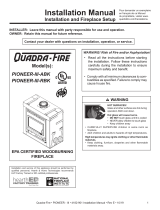
Termination Cap
Chimney penetrates roof
preferably without affecting
roof rafters
Offset/Return
(with hanger straps)
Attic insulation shield
must be used to keep
insulation away
from chimney if
attic is insulated
Storm Collar
Framing headed
off in ceiling joists
Mantel
Chimney system
Combustible
framing/header
on top of V-shaped
standoffs (spacers)
Non-combustible material
Hearth extension
Non-combustible
roof flashing maintains
minimum clearance
around chimney
Additional lateral
support for chimney
above roof (or enclosed
in chase) if needed
Enclosed space above
and around fireplace
Ceiling firestop
on floor of attic
Support straps
on rafter supports
chimney (not shown)
Outside
combustion air
Outside
combustion air
Chimney Air Kit (CAK-4A) (not
shown) must be used with SL300
chimney
Protective metal
hearth strip(s)
A. Typical Fireplace System
Figure 2.1 Typical Fireplace System
6
Quadra-Fire • 7100 FP • 433-3610 Installation Manual • Rev U • 12/18

D
C
A
E
F
A
H
G
B
A
B
B
A
I
In an exterior chase
or projecting into a
garage
Across a corner
Along a wall
As a
room
divider
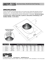
24 in.
(610mm)
24 in.
(610mm)
24 in.
(610mm)
48 in.
(1219mm)
*If interior of chase will be drywalled,
add the thickness to this
measurement.
°Faceplate to sidewall
24 in.
(610mm)
I
A
*
*
*
*
Figure 2.2 Fireplace Locations
NOTICE:
• Illustrations and photos reect typical installations and
are FOR DESIGN PURPOSES ONLY.
• Illustrations/diagrams are not drawn to scale.
• Actual installation/appearance may vary due to individual
design preference.
• Hearth & Home Technologies reserves the right to alter
its products.
NOTICE: In addition to these framing dimensions, also
reference the following section:
• Clearances (Section 3).
NOTICE:
A minimum 1/2 in. air clearance at the back and
a minimum 1 in. air clearance to the sides of the
replace assembly must be maintained.
Chimney sections at any level require a 2 in. mini-
mum air space clearance between the framing
and chimney sections.
B. Design and Installation Considerations
NOTICE: Check building codes prior to installation.
• InstallationMUSTcomplywithlocal,regional,stateand
national codes and regulations.
• Consultinsurancecarrier,localbuildinginspector,re
ofcialsorauthoritieshavingjurisdictionoverrestrictions,
installation inspection and permits.
1. Selecting Fireplace Locations
This replace may be used as a room divider, installed
along a wall, across a corner or used in an exterior chase.
See Figure 2.2.
Locating the replace in a basement, near frequently
opened doors, central heat outlets or returns, or other loca-
tionsof considerable airmovementcanaffecttheperfor-
mance.
Outside air must be used for combustion. The 7100FP
comesequippedwithanoutsideairinlettofeedcombus-
tion air from outside the home, along with an outside air
terminationcap;themetalductisrequiredbutnotsupplied.
Considerationshouldbegiventothesefactorsbeforede-
ciding on a location.
Model # 7100FP A B° C D E F G H I
(Dimensionsfor
nishedwalls)
in. 42-1/2 16 89-1/2 63-5/16 22-7/16 44-3/4 14-1/16 56-9/16 54-1/2
mm 1080 406 2273 1608 570 1137 357 1437 1384
7
Quadra-Fire • 7100 FP • 433-3610 Installation Manual • Rev U • 12/18

2. Locating Fireplace & Chimney
Locationofthereplaceandchimneywillaffectperfor-
mance.
• Installwithinthewarmairspaceenclosedbythebuilding
envelope.Thishelpstoproducemoredraft,especially
duringlightinganddie-downofthere.
• Penetratethehighestpartoftheroof.Thisminimizes
the effects of wind loading.
• Locate termination cap away from trees, adjacent
structures,unevenrooflinesandotherobstructions.
• Minimize the use of chimney offsets.
• Considerthereplacelocationrelativetooorandceiling
and attic joists.
• Takeintoconsiderationtheterminationrequirementsin
Sections5and6.
Marginal Location:
• Below peak
Location NOT recommended:
• Not the highest point of the roof
• Wind loading possible
Multi-level Roofs
Windward
Leeward
Recommended Location:
• Above peak
Recommended:
• Insulated exterior chase
in cooler climates
Recommended Location:
• Above peak
• Inside heated space
Location NOT recommended:
• Too close to tree
• Below adjacent structure
• Lower roof line
• Avoid outside wall
Marginal Location:
• Wind loading possible
Not recommended in basement due
to high negative pressure concerns
that effect draft
Figure 2.3 Recommended Chimney Locations
• Installtheoutsideairkitwiththeintakefacingprevailing
winds during the heating season.
• Ensure adequate outdoor air for all combustion
appliancesandexhaustequipment.
• Ensurefurnaceandairconditioningreturnventsarenot
locatedintheimmediatevicinityofthereplace.
• Avoidinstallingthereplaceneardoors,walkwaysor
small isolated spaces.
• Recessedlightingshouldbea“sealedcan”design.
• Attic hatches weather stripped or sealed.
• Attic mounted duct work and air handler joints and seams
taped or sealed.
8
Quadra-Fire • 7100 FP • 433-3610 Installation Manual • Rev U • 12/18

C. Tools and Supplies Needed
Beforebeginningtheinstallationbesurethefollowing
toolsandbuildingsuppliesareavailable:
Reciprocating saw Framing material
Pliers Non-combustiblesealant
Hammer Gloves
Phillipsscrewdriver Framingsquare
Flatbladescrewdriver Electricdrillandbits
Plumbline Safetyglasses
Level Tapemeasure
1/2-3/4in.length,#6or#8self-drillingscrews
Misc. screws and nails
D. Inspect Fireplace and Components
WARNING! Risk of Fire and/or Explosion! Damaged
parts could impair safe operation. DO NOT install dam-
aged, incomplete or substitute components. Keep re-
place dry.
• Removereplaceandcomponentsfrompackagingand
inspect for damage.
• Vent system components and doors are shipped in
separate packages.
• Report to your dealer any parts damaged in shipment.
• Read all the instructions before starting the
installation. Follow these instructions carefully
during the installation to ensure maximum safety
and benet.
E. Fireplace System Requirements
TheQuadra-Firereplacesystemrequirementsconsistof
thefollowing:
• Fireplace
- Firebrick(includedwithreplace)
- Door(includedwithreplace)
- Non-combustible facing material (included with
replace)
- HearthExtension
• OutsideAir System (hood and collars included with
replace)
• Fascia
• Chimney System
- Chimneyairkit(includedwithreplace,requiredwith
SL300serieschimney)
- AtticInsulationShield(includedwithreplace)
- Chimney termination cap
• Non-combustiblenishmaterial
Optionalcomponentsinclude:
• Firescreen
• Lintel Bar
• HeatZoneKit
9
Quadra-Fire • 7100 FP • 433-3610 Installation Manual • Rev U • 12/18

3
Framing and Clearances
A. Fireplace Dimensions
C
L
Blower Electric Access
(right side of fireplace)
3-1/2 in.
(89 mm)
32-1/2 in.
(826 mm)
38 in.
(965 mm)
40 in.
(1016 mm)
42-5/16 in.
(1075 mm)
45-13/16 in.
(1148 mm)
23-7/16 in.
(595 mm)
13-3/16 in.
(335 mm)
10-13/16 in.
(259 mm)
4-5/16 in.
(109 mm)
6 in.
(152 mm)
1 in.
(25 mm)
13-3/4 in.
(349 mm)
9-7/16 in.
(240 mm)
42 in.
(1067 mm)
Auxilary
Outside Air
3 in.
(76 mm)
1in.
(25 mm)
1/2 in.
(13 mm)
Figure 3.1 Fireplace Dimensions
10
Quadra-Fire • 7100 FP • 433-3610 Installation Manual • Rev U • 12/18

B. Clearances
WARNING! Risk of Fire!
You must comply with all minimum air space clearances to combustibles as specied in Figure 3.2. DO NOT pack required
air spaces with insulation or other materials. Framing or nishing material used on the front of, or in front of, the replace
closer than the minimums listed must be constructed entirely of non-combustible materials (i.e., steel studs, concrete board,
etc.). Failure to comply may cause re.
Figure 3.2 Clearances to Combustible Materials
(ceiling)
(roof)
(ceiling)
2 in. (51 mm) min.
Attic
Insulation
Shield
Ceiling Firestop
(attic)
Storm Collar
Roof Flashing
2 in. min.
(51 mm)
2 in. (51 mm) min.
2 in. (51 mm) min.
Ceiling Firestop
Offset/Return with
hanger straps
2 in.
(51 mm)
min.
2 in. (51 mm) min.
Must have 2 in. (51 mm)
minimum clearance
to header
Electrical wires must be 3-1/2: (89mm)
from top
0 in. to level
of standoffs
1 in. (25mm) to side of appliance
1/2 in. (13 mm) to back
of appliance
0 in.
to floor
36 in. (914 mm)
standoffs to ceiling
Chimney Air Kit required with SL chimney
11
Quadra-Fire • 7100 FP • 433-3610 Installation Manual • Rev U • 12/18

1. Minimum Clearances to Combustibles
Position combustible mantel
60 in. (1524 mm) from
base of fireplace.
12 in.
(305 mm)
46-1/4in.
(1175 mm)
24 in.
*
(610 mm)
48-1/2 in.
(1232 mm)
42-1/2in.
(1080 mm)
The finished cavity depth must
be no less than 24 in. (610 mm)
from the finished backwall to the
outside of front wall framing.
2 x 4s must be used for the
header and framing above
the header to maintain pipe
clearances.
*If interior of chase will be drywalled, add the thickness to this measurement.
12 in.
(305 mm)
When installing the
outside air with an
elbow/bend, allow a
minimum cavity of 12 in.
(305mm)
14 1/2 in. (368 mm) for
SL300 Chimney
16 in. (406 mm) for
DuraPlus Chimney
Position non-combustible mantel 46 in.
(1168 mm) from base of fireplace. Must
use non-combustible framing and Durock
above the fireplace to ceiling or 8 foot up
with a vaulted ceiling.
Double studs to catch
non-combustible board
and wall facing material.
Figure 3.3 Framing the Fireplace
WITHIN ENCLOSURE AREA
Fireplacetobackwall 1/2in.(13mm)
Fireplace to sidewall 1in.(25mm)
Ductbootstoframing 0in.(0mm)
Topstandoffstoheader 0in.(0mm)
Door opening to sidewall 22-7/8in.(581mm)
EXPOSED SURFACES
Faceplate to sidewall 16in.(406mm)
Heatzoneairgrillstoceiling 12in.(305mm)
MANTEL
Non-combustiblemantel
(Non-combustibleframing
materialsabovethereplace
toceiling) 46in.(1168mm)
Combustiblemantel
(Combustibleframing
materialsabovethereplace
toceiling) 60in.(1524mm)
Maximum mantel depth 12in.(305mm)
12
Quadra-Fire • 7100 FP • 433-3610 Installation Manual • Rev U • 12/18
►

C. Construct the Chase
Achaseisaverticalboxlikestructurebuilttoenclosethe
replaceand/oritsventsystem.Verticalchimneysthat
runontheoutsideofabuildingmustbeinstalledinsidea
chase.
Incoldclimates,Hearth&HomeTechnologiesrecom-
mendsthatthechasebewellinsulatedusingbatttype
insulationbetweenthejoists.
Constructionofthechasemayvarywiththetypeofbuild-
ing.Theseinstructionsarenotsubstitutesfortherequire-
mentsoflocalbuildingcodes.LocalbuildingcodesMUST
bechecked.
Chasesshouldbeconstructedinthemannerofalloutside
wallsofthehometopreventcoldairdraftingproblems.
Thechaseshouldnotbreaktheoutsidebuildingenvelope
inanymanner.Allouterwallsneedtobeinsulated.
Buildingcodesrequirefalseceilingandceilingrestops/
atticshieldsateachoorofthechaseorevery10ft(3048
mm)ofclearspacetocontrolspreadofre.
Walls,ceiling,baseplateandcantileveroorattherst
levelofthechaseshouldbeinsulated(seeFigure3.4.)
Vaporandairinltrationbarriersshouldbeinstalledinthe
chase as per regional codes for the rest of the home. Ad-
ditionally,Hearth&HomeTechnologiesrecommendsthat
theinsidesurfacesbedrywalledandtaped(ortheuseof
anequivalentmethod)formaximumairtightness.
Holesandotheropeningsshouldbecaulkedwithhigh
temperaturecaulkorstuffedwithunfacedberglass
insulation.
Ceiling
Firestop
Metal Chase Top
Round Termination Cap
False Ceiling
Insulation in the
outside walls
of the chase
Attic
Insulation
Shield
Chimney
Ceiling
Firestop
Tabs
False Ceiling
False Ceiling
Insulation
Insulation
Storm Collar
Figure 3.4 Chase Assembly
1 2 3
All outside walls should be insulated.
Figure 3.5 Chase Constructions
1. Fireplace and chimney enclosed in an exterior chase.
2. Chimney offset through exterior wall and enclosed in chase.
3. Chase constructed on roof.
• Thechaseisconstructedusingframingmaterialsmuch
thesameasthewallsinyourhome.Avarietyofsiding
materials may be used including brick, stone, veneer
brick,orstandardsidingmaterials.
• In constructing the chase, several factors must be
considered:
- Maintain a 2 in. (51 mm) air space around the
chimney.
- The chase top must be constructed of non-
combustiblematerial.
- Incoldclimates,arestopspacerandatticinsulation
shieldshouldbeinstalledinaninsulatedfalseceiling
at the 8 ft. (2438 mm) level above the replace
assembly.Thisreducesheatlossthroughthechase.
- Incold climates, the walls of the chase should be
insulatedtothelevelofthefalseceilingasshownin
Figure3.4.Thiswillhelpreduceheatlossfromthe
homearoundthereplace.
ThreeexamplesofchaseapplicationsareshowninFig-
ure3.5.
WARNING! You must install false ceilings and ceil-
ing restops at each oor of the chase or every 10 ft
(3.05 m) to control spread of re.
WARNING! Risk of Fire! DO NOT seal area between re
stop opening and chimney pipe except where they enter
the attic or leave the warm air envelope of the home (use
600° F sealant).
WARNING! Risk of Fire! You must maintain a minimum
2 in. (51 mm) air space clearance to insulation and other
materials surrounding the chimney system.
• Insulation and other materials must be rmly secured to
prevent accidental contact with chimney system.
• The chase must be properly blocked to prevent blown
insulation or other combustibles from entering and
making contact with replace or chimney.
• Failure to prevent contact between insulation or other
materials and chimney system may cause overheating
and re.
13
Quadra-Fire • 7100 FP • 433-3610 Installation Manual • Rev U • 12/18

D. Frame the Fireplace
NOTICE: Hearth extension design must be determined
beforeinstallationofreplace.
Ifthereplaceisplacedontheoorthemaximumheight
ofanishedraisedhearthis5-3/4”,ifyouwantahigher
raisedhearththereplacemustbeplacedonaplatform.
NOTICE: Wiring for fans must be done before framed
enclosure is completed. If using a Heat Zone Kit, it
also must be installed before enclosure is complete.
WARNING! Risk of Fire! You must comply with all
minimum air space clearances to combustibles. DO NOT
pack required air spaces with insulation or other materi-
als.
WARNING! Risk of Fire! Comply with all minimum clear-
ances specied.
• A minimum 1/2 in. (13 mm) air clearance must be
maintained at the back and 1 in. (25 mm) to the sides
of the replace assembly.
• Chimney sections at any level require a 2 in. (51 mm)
minimum air space clearance between the framing and
chimney section.
Figure3.3showsatypicalframing(using2x4lumber)
ofthereplace,assumingcombustiblematerialsareused.
All required clearances to combustibles around the re-
place must be adhered to. See Figure 3.2.Any framing
acrossthetopofthereplacemustbeabovethelevelof
thetopstandoffs.(Norecessabovestandoffs.)
The
nished cavity depth must be no less than 24 in.
(610mm)fromthenishedbackwalltotheoutsideoffront
wall framing. Framing must extend straight up all the way
to the ceiling.
CAUTION! Risk of Cuts/Abrasions. Wear protective gloves
and safety glasses during installation. Sheet metal edges
are sharp.
WARNING! Risk of Fire! Prevent contact with sagging,
loose insulation.
• DO NOT install against vapor barriers or exposed
insulation.
• Secure insulation and vapor barriers.
• Provide minimum air space clearances at the sides and
back of the replace assembly as outlined in Section 3.
E. Secure and Level the Fireplace
This replace may be placed on either a combustible or
noncombustiblecontinuousatsurface.Followtheinstruc-
tionsforframinginSection3.Slidethereplaceintoposi-
tion.Besuretoprovidetheminimum1in.airclearanceat
thesidesand1/2in.atthebackofthereplace.
Thereplaceshouldbepositionedsothefaceofthenon-
combustiblematerialonthereplacewillbeushwiththe
faceofthedrywallonthewalls.SeeFigure3.6.
Levelthereplaceandshimasnecessary.Securethere-
place(usingthepalletmountingbracketslocatedoneither
sideofthereplace)tothesuboor.
These surfaces
must be even!
Drywall Non-combustible
facing material
Figure 3.6 Drywall - Non-combustible Facing Material
Standoffs are attached to the replace.
The unit can be positioned with the standoffs touching
combustiblewallsorframingbutDONOTpackinsulation
orothermaterialsintheairspacebetweenthereplace
and wall.
14
Quadra-Fire • 7100 FP • 433-3610 Installation Manual • Rev U • 12/18

1in. (25 mm) Overlap
Metal strips 2 in. (51 mm) under edge of Fireplace
and Hearth Extension and extended 2 in. (51 mm)
beyond both sides of fireplace opening.
Nail or screw metal strips in place.
Pallet Mounting/Floor
Brackets
Raised Platform
Floor
2 in.
(51 mm)
1 in. (25 mm) min.
overlap
2 in.
(51 mm)
Top piece must overlap
bottom piece
Figure 3.8 Protect the Front of an Elevated Platform
F. Protective Metal Hearth Strips
Figure 3.7 Position the Protective Metal Hearth Strips
• Locatethetwoprotectivemetalhearthstripsmeasuring
approximately26in.x4in.(660mmx102mm)included
withthisreplace.
• Slideeachmetalstrip2in.(51mm)underfrontedgeof
replace.
• Overlapstripsinthemiddleofreplaceopeningby1in.
(25mm)minimum.
• Metal strips must extend beyond the front and sides
of the replace opening by at least 2 in. (51 mm),
Figure3.7).
• Protectthefrontofaplatformelevatedabovethehearth
extensionwithmetalstrips(notincludedwithreplace)
per Figure 3.8. See Section 6 for hearth extension
instructions.
WARNING! Risk of Fire! Protective metal hearth
strips MUST be installed on combustible surfaces. DO
NOT cover metal strips with combustible materials.
Sparks or embers may ignite ooring.
WARNING! Risk of re! High temperatures, sparks,
embers or other burning material falling from the
replace may ignite ooring or concealed combustible
surfaces.
• Protective metal hearth strips MUST be installed.
• Hearth extensions MUST be installed exactly as
specied.
WARNING! Risk of Fire!
Follow these instructions exactly.
Facing materials must be installed properly to prevent
re.
No materials may be substituted without authorization by
Hearth & Home Technologies.
G. Facing Material
TOOLS NEEDED: Powered drill with #2 Phillips head bit;
caulking gun.
Onlynon-combustiblematerials(suppliedwithreplace)
maybeusedtocoverthemetalreplacefront.
NOTE: All boards are pre-drilled for your convenience.
Boards MUST be attached in the following order:
bottom, top, and then the two sides, red-painted side
out. The top and bottom board should each have a hang
tag attached. Leave them attached for referral for the
nishing operation.
• Attach the bottom board to the bottom of the outer
replacecanwithenclosedscrews,ensuringtheboard
is centered. DO NOT remove hang tags.
• Centerandattachthetopboardtotheoutercanand
framingmembers. DO NOT remove hang tags.
• Using the Super Calstick or equivalent 1000°F high
temperaturesealant,runalightbead(1/8in.minimum)
betweenthemetalsurfaceofthereplaceandthebutt
edgesofthetopboard.SeeFigure3.9.
• Ensuringthetopofthesidepiecesandthetopboard
align, attach the side pieces to the outer can and framing
members.
NOTICE: 1/8 in. of the facing material may be visible
after nishing materials are applied. This 1/8 in. must
be painted or the red will show.
Figure 3.9 Apply Non-combustible Materials
Side
Board
Bottom
Board
Side
Board
Top
Board
DO NOT
remove hang
tags
Apply bead of Super
Calstick or equivalent
1000°F high tempera-
ture sealant to edge
here
15
Quadra-Fire • 7100 FP • 433-3610 Installation Manual • Rev U • 12/18
►
►

H. Outside Air Kit
Anoutsideairkitmustbeusedforcombustion.Hearth&
HomeTechnologiesrecommendsyouutilizetheshortest
duct run to optimize the performance of the outside air
kit.Theoutsideairinlethoodshouldbepositionedina
mannerthatwillnotallowsnow,leaves,etc.toblockthe
inlet.Insomeinstallationstheairductmayneedtoberun
vertically.Insuchaninstallation,a3ft(914mm)height
differencemustbemaintainedfromthetopoftheupper-
most chimney section to the outside air inlet hood.
Refer to Figures 3.10 and 3.11 when placing the outside
air inlet hood.
Theoutsideairkitisinstalledontherighthandsideofthe
replace.SeeFigure3.12forhandlelocation/operation.
• Cut a 6-1/2 in. (165 mm) hole in outside wall to
accommodate air piping.
• Use6in.(152mm)metalexorrigidpiping(notsupplied)
todirectlyconnectoutsideairtoreplaceintake.Insulate
thepipetopreventfrostcondensation.
• Insulating the pipe isn’t required but will help prevent
frost condensation.
• Use the supplied outside air inlet hood.
• Seal between the wall and the pipe with silicone to
preventmoisturepenetrationandairleaks.
• Sealbetweentheoutsideairinlethoodandthehouse
withsiliconetopreventairinltration.
CAUTION! Risk of Cuts/Abrasions. Wear protective
gloves and safety glasses during installation. Sheet metal
edges are sharp.
CAUTION! Risk of Fire or Asphyxiation! DO NOT draw
outside combustion air from wall, oor or ceiling cavity, or
enclosed spaces such as an attic or garage.
• DO NOT place outside air inlet hood close to exhaust
vents or chimneys. Fumes or odor could be drawn into
the room through the replace.
• Locate outside air inlet hood to prevent blockage from
leaves, snow/ice, or other debris. Blockages could cause
combustion air starvation.
16
Quadra-Fire • 7100 FP • 433-3610 Installation Manual • Rev U • 12/18

3 ft. (91cm) min. from
top of uppermost
chimney section to
outside air inlet.
Locate outside air inlet
to prevent blockage
from leaves, snow/ice,
or other debris.
Attic insulation shield
must be used to keep
insulation away from
chimney.
Ceiling firestop
on floor of attic
Outlet blocked by
snow, leaves, etc.
NO
Garage or
combustible
liquids storage
NO
Attic space
NO
Outlet placed
higher than 3 ft
below the
termination cap
NO
UL181 Listed Class 0
or Class 1 metal flex or
rigid duct
Clear area
outside
house or in
ventilated
crawl space
YES
Figure 3.11 Outside Air Installation
Figure 3.10 Outside Air Inlet Locations
17
Quadra-Fire • 7100 FP • 433-3610 Installation Manual • Rev U • 12/18

I. Auxiliary Convection Air System
Note: Both the outside air and auxiliary air kits are installed
ontherighthandsideofthereplace.
Theauxiliaryconvectionairsystemallowstheoptionat
thetimeofinstallationofthereplace,toruna6inch
(152mm)diameterducttotheoutsideofthehome,and
bringoutsideairoverthefanswhereitisheatedandthen
distributedintotheroom.Thisproducesapostivepres-
sure inside the home.
Figure 3.13 Auxiliary Convection Air Duct
Alternatively,a6inch(152mm)ductcanberuntoan-
other location in the home and used as a cold air return
withinthehomeanddistributedintotheroomwherethe
replaceislocated.SeeFigure3.13.
If no ducting is installed, the fans will pull air from the
roomandre-circulateheatedairbackintotheroom.
Figure 3.12 Outside Air
Termination
Caps supplied
with fireplace
UL 181 Listed Class 0 or Class
1 metal flex or rigid duct
Outside Air
intake
Auxiliary
Convection
Air
Open/Close
Knob for
outside air
OUTSIDE AIR
OPEN
CLOSED
Auxiliary Convection Air Lever
Theauxiliaryconvectionairleveris locked from the fac-
tory.Ifyouaregoingtousethisfunctionforairmovement
youmustremovethelock.
Afterremovingthefascia,removetheonescrewandplate
toallowthehandletobemovedinthefullmotionrightto
left.SeeFigure3.14.
Discard the plate and screw. Replace fascia.
The auxiliary convection lever is located underneath the
frontlowerpanelasshowninFigure3.14.
Figure 3.14 Auxiliary Convection Air Lever
8-32 Screw
Convection Lock Bracket
NOTICE:
If you live in an area with very cold winter months, you
will want to use room air as opposed to bringing in ex-
tremely cold air from outside of the home. This will
eliminate creating a draft of cold outside air inltrating
your home. Denitely keep the lever to the LEFT when
not using the replace if the duct has been installed.
18
Quadra-Fire • 7100 FP • 433-3610 Installation Manual • Rev U • 12/18

DUCT RUN REQUIREMENTS
MAXIMUMDuctRun=40-ft.(12m)
MINIMUMDuctRun=36in.(914mm)
DUCTING MATERIAL
6in.(152mm)B-VentOnly
DONOTductintoexistingfurnaceplenum
MINIMUM CLEARANCE TO COMBUSTIBLES
1in.(25mm)fromtheB-Vent
1
/2in.(13mm)fromtop&bottomofoutletbox
0in.(0mm)fromthesidesofoutletbox
12in.(305mm)fromwallregistertoceiling
RefertoFigure3.15.
CAUTION! ALL wiring should be done by a qualied elec-
trician and shall be in compliance with local codes and
with the National Electric Code NFPA/NEC No. 70-current.
CSC22.1 Canadian Electric Code.
Possible Air Duct Runs / Locations
Figure 3.15 Minimum Clearances to Combustibles
J. Heat Zone Kit (Optional)
TheHeat-Zoneaccessorykitconveyswarmairfromthe
replacethroughairduct(s)toremotelocationsinthe
sameroomorotherroomsofthebuilding.Youmayinstall
1or2Heat-Zonekitsonthereplace.Installationofthis
kit MUSTbeperformedbyaqualiedservicetechnician.
If any parts are missing or damaged, contact your local
dealerbeforestartinginstallation.DONOTinstalladam-
aged kit.
Thiskitistestedandsafewheninstalledinaccordance
withthisinstallationmanual.Itisyourresponsibilityto
readallinstructionsbeforestartinginstallationandtofol-
low these instructions carefully during installations.
TheHeat-Zone®Woodkitiscarefullyengineeredand
mustbeinstalledonlyasspecied.Ifyoumodifyitorany
ofitscomponentsyouwillvoidthewarrantyandyoumay
possiblycausearehazard.Installationmustbedone
accordingtoapplicablelocal,state,provincialand/or
national codes.
Planthelocationofthereplaceandwarmairductrun(s).
Ceiling Register
Wall Register
Floor Register
Two Duct Kits
Ceiling Register
12 in. (305mm) minimum clearance
from register to ceiling
17 in. (432mm) minimum
clearance to allow for
venting
19
Quadra-Fire • 7100 FP • 433-3610 Installation Manual • Rev U • 12/18

Installation
• Removetheknockoutorcoverplatefromthetopofthe
replaceanddiscardit.SeeFigure3.16.
• Cuta3in.(76mm)holeintheinsulationboardasper
thedimensionsshowninFigure3.16.
Adapter
Mounting
Plate
Starter Pipe
Knockout
Cut a 3 in. (76 mm)
hole in insulation board
3-13/16 in.
(97 mm)
3-1/8 in. (79 mm)
C
L
Run Length Cut Pipe
20 - 40 ft (6-12 m) 2 in. (51 mm)*
*A minimum of 2 in. (51 mm) pipe must be used to
cover the raw insulation to prevent it from blowing
out through the return air grille.
10 - 20 ft (3 - 6 m) 8 in. (203 mm)
3 - 10 ft (1 - 3 m) No cut needed**
**Use full 16 in. (406 mm) as supplied
• Determine the necessary length of starter pipe from the
Table3.1andcutasrequired.
Figure 3.16
• Slide the starter pipe into the replace, matching the
holesintheplatetotheholesinthereplace.
• Place the adapter on the mounting plate lining up holes.
Using four sheet metal screws included in the kit, secure
the adapter and mounting plate into replace.After
securingtothereplace,tapedowntheadapteredges
tothetopofthereplacewithaluminumtapetoprevent
leakage.
• Determine the location for the air register and fan
housingassembly.Cuta7-5/8in.x13-5/8in.(143mm
x346mm)holebetweenframingmembers(wallstuds
oroorjoists).Thebracketscanberotated180°and
mountedtothebacksideofthe2x4ifnecessary.See
Figure3.18.
NOTICE: The fan and electrical connections must be
accessible for servicing per local code requirements.
NOTICE: If the fan housing is installed in a 2 x 4 wall,
the front of the housing will protrude approximately 1/4
in. (6 mm) from the nished wall.
• Attach enough6 in.(152 mm) B-Vent as required for
your installation to the fan housing. A maximum of (4)
90° elbows is recommended. Securely twist lock the
B-Vent to the adapter.
AlsoscrewtheB-Venttotheoutletboxonthefan
housing.SeeFigure3.19.
Supportductatintervals
ofnogreaterthan4ft(1m)asrequiredbylocalcode.
Figure 3.17
WARNING! Risk of Fire! Comply with all minimum
clearances specied.
• A minimum 1 in. (13 mm) air clearance must be
maintained at the back and 1 in. (25mm) to the sides
of the replace assembly.
NOTE: It is important the pipe length be adhered to
or it will affect the performance of your replace.
• Onthemountingplate,handbendthetabsdownward.
Slidethetabsovertheoutsideofthestarterpipe.Secure
with four sheet metal screws included in fasteners
package. Figure 3.17.
Table 3.1
20
Quadra-Fire • 7100 FP • 433-3610 Installation Manual • Rev U • 12/18
/