Reely 1302975 Operating instructions
- Category
- Remote controlled toys
- Type
- Operating instructions
Page is loading ...
Page is loading ...
Page is loading ...
Page is loading ...
Page is loading ...
Page is loading ...
Page is loading ...
Page is loading ...
Page is loading ...
Page is loading ...
Page is loading ...
Page is loading ...
Page is loading ...
Page is loading ...
Page is loading ...
Page is loading ...
Page is loading ...
Page is loading ...
Page is loading ...
Page is loading ...
Page is loading ...
Page is loading ...
Page is loading ...
Page is loading ...
Page is loading ...
Page is loading ...
Page is loading ...
Page is loading ...

29
Table of Contents
Page
1. Introduction ........................................................................................................................................................30
2. Explanation of Symbols .....................................................................................................................................31
3. Intended Use .....................................................................................................................................................31
4. Product Description ...........................................................................................................................................31
5. Scope of Delivery ...............................................................................................................................................32
6. Safety Information ..............................................................................................................................................33
a) General ........................................................................................................................................................33
b) Before Commissioning ................................................................................................................................33
c) During Operation .........................................................................................................................................34
7. Information on Batteries and Rechargeable Batteries .......................................................................................35
8. Model Setup .......................................................................................................................................................36
a) Mounting the Elevators and Rudders ..........................................................................................................37
b) Checking the Linkage Rods at the Ailerons .................................................................................................38
c) Mounting the Wings .....................................................................................................................................39
d) Securing the Wings for Flight Operation ......................................................................................................40
e) Installing the Propellers ...............................................................................................................................41
9. Motor Commissioning ........................................................................................................................................42
a) Commissioning the Remote Control ............................................................................................................42
b) Charging the Flight Battery ..........................................................................................................................42
c) Mounting the Elevator and Rudder Linkage Rods .......................................................................................42
d) Inserting and Connecting the Flight Battery ................................................................................................43
e) Setting the Centre of Gravity .......................................................................................................................44
f) Checking the Control Functions ..................................................................................................................44
g) SettingtheRudderDeections ....................................................................................................................48
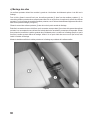
10. Flying the Model in .............................................................................................................................................49
a) Range Test ..................................................................................................................................................49
b) Take-Off .......................................................................................................................................................49
c) Curve Flight .................................................................................................................................................49
d) Trimming the Model .....................................................................................................................................50
e) The First Touch-Down .................................................................................................................................50
11. Propeller change ................................................................................................................................................51
12. Programming the Flight Controller .....................................................................................................................52
a) Neutral Position (Motor Off) .........................................................................................................................52
b) Motor brake .................................................................................................................................................52
c) Other Programming Options ........................................................................................................................52
d) Undervoltage Recognition per Battery Type ................................................................................................53
(

30
Page
e) Battery Type „LiPo“ ......................................................................................................................................53
f) Battery Type „NiMH“ ....................................................................................................................................53
g) Battery Type „LiFe“ ......................................................................................................................................53
h) Motor Timing ................................................................................................................................................53
13. Maintenance and Care ......................................................................................................................................54
14. Disposal .............................................................................................................................................................54
a) General ........................................................................................................................................................54
b) Batteries and Rechargeable Batteries .........................................................................................................54
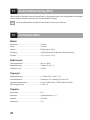
15. Declaration of Conformity (DOC) .......................................................................................................................55
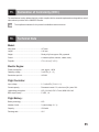
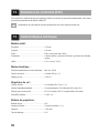
16. Technical Data ...................................................................................................................................................55
1. Introduction
Dear Customer,
thank you for purchasing this product.
This product complies with the statutory national and European requirements.
To maintain this status and to ensure safe operation, you as the user must observe these operating instructions!
These operating instructions are part of this product. They contain important notes on commissioning and
handling. Also consider this if you pass on the product to any third party.
Therefore, retain these operating instructions for reference!
All company names and product names are trademarks of their respective owners. All rights reserved.
If there are any technical questions, please contact:
International: www.conrad.com/contact
United Kingdom: www.conrad-electronic.co.uk/contact

31
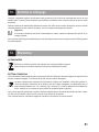
2. Explanation of Symbols
The symbol with the exclamation mark points out particular dangers associated with handling, function or
operation.
The „arrow“ symbol indicates special advice and operating information.
3. Intended Use
This product is an model airplane with wireless radio control through a remote control system. The model is intended
foroutdooruseanddesignedforightmodelsportsbeginners.
The product must not become damp or wet.
The product is not suitable for children under 14 years of age.
Observe all safety information in these operating instructions. They contain important information on hand-
ling of the product.
You are solely responsible for safe operation of the model!
4. Product Description
Theightmodel„PhönixPlus“isamodelgliderwithanelectricalenginethatisdesignedformodelpilotbeginners.
Completion and later operation only require a little knowledge on the handling of model planes.
ThemodelisentirelymadeofEPO(=expandedpoly-olen)andhasbeenappliedwithdecorativelm.Thisspecial
materialishighlyexibleandresistant,whichmakesitperfectforbeginners‘modelight.
Inadditiontotheightmodel,allrequiredpartsfortherudderlinkages,aswellasa2.4GHzremotecontrolsystem
are enclosed.
The user can control: Aileron, elevator and rudder as well as speed control of the motor.
Theseoperatinginstructionsincludethecorrespondingguresforeachconstructionsectionthatpresents
the most essential parts. Special features are noted in the text.
Theguresserveillustrationpurposesandmaydeviatefromtheactualdeliveryincolouranddesigninthe
ightmodelaswellastheremotecontrol.

32
5. Scope of Delivery
Before you start assembly, check the parts for the scope of delivery of your model.
• Fuselagewithcanopy
• Leftandrightwings
• Elevatorrudder
• Fin
• Wingrod(wingconnector)
• Propeller
• Flightbattery
• Transmitter
• Operatinginstructionsforightmodel
• Operatinginstructionsforremotecontrolsystem
The following components not included in delivery are required for assembly and operation:
• Sharpcutterknife
• Finesandpaper
• Screwdriversofdifferentsizes
• LiPochargerforchargingtheightbattery
• Chargingcablewithtee
• FourbatteriesoftypeAA/Mignonforthetransmitter
See our catalogues or our website at www.conrad.com for tried and tested accessories.

33
6. Safety Information
In case of damage caused by non-compliance with these operating instructions, the warranty/gua-
rantee will expire. We do not assume any liability for consequential damage!
We do not assume any liability for property damage and personal injury caused by improper use or
non-compliance with the safety instructions! In such cases the warranty/guarantee is voided.
Normal wear and tear and accident and crash damage (e.g. broken rotor or other broken parts) are also
excluded from the guarantee and warranty.
Dear Customer,
this safety information serves not only to protect the product, but also your own safety and the safety of other
persons. Therefore, read this chapter very carefully before taking the product into operation!
a) General Information
Caution, important note!
Operating the model may cause damage to property and/or individuals. Therefore, make sure that you are
sufcientlyinsuredwhenusingthemodel,e.g.bytakingoutprivateliabilityinsurance.Ifyoualreadyhave
private liability insurance, verify whether or not operation of the model is covered by your insurance before
commissioning your model.
Note:SomeEUcountriesrequireinsuranceforallightmodels!
• Theunauthorizedconversionand/ormodicationoftheproductoritscomponentsisinadmissibleforsafetyand
approval reasons (CE).
• Thisproductisnotatoyandnotsuitableforchildrenunder14yearsofage.
• Theproductmustnotbecomedamporwet.
• Ifyoudonothavesufcientknowledgeregardinghandlingofremote-controlledmodels,contactanexperienced
model sportsman or model construction club.
•Donotleaveanypackagingmaterialunattended.Itmaybecomeadangerousplayingmaterialforchildren.
• Shouldquestionsarisethatarenotansweredbytheseoperatinginstructions,contactus(forcontactinformation,
see chapter 1) or another expert.
b) Before Commissioning
• Perform suitable tests to ensure that your remote control is not impaired by concurrent operation of several
2.4GHz-remotecontrolsystemsandthatyourremotecontroldoesnotimpairanyothermodelsintheirfunction.
• Regularlycheckthefunctionalsafetyofyourmodelandoftheremotecontrolsystem.Watchoutforanyvisible
damage such as defective plug connections or damaged cables. All moving parts on the model must run smoothly
but must not have any tolerance in the bearing.
• Therechargeablebatteriesrequiredforoperation(e.g.remotecontroltransmitters,ightbattery)mustbecharged
accordingtothemanufacturer‘sspecications.
• Ifbatteriesareusedasatransmitterpowersupply,makesurethattheyhavesufcientremainingcapacity(battery
checker). If the batteries are empty, always replace the complete set, never individual cells only.

34
• Beforeeachoperation,checkthesettingsofthetrimslideronthetransmitterforthedifferentsteeringdirectionsand,
if necessary, adjust them.
• Alwayscheckthecorrectandsecurepositionofthepropellerbeforeoperation.
• Regularlyexaminethepropellerfordamage.Damagedpropellersposeadangerandnolongermustbetakeninto
operation.
• Alwaysswitchonthetransmitterrst.Onlythencanthereceiversystembetakenintooperationbyconnectingthe
ightbatteryinthemodel.Otherwise,theremaybeunpredictableresponsesandtherotormaystartunintentio-
nally.
• Makesurethatneitherobjectsnorbodypartsareintherotatingandsuctionareasofthepropellerwhileitisrota-
ting.
c) During Operation
• Donottakeanyriskswhenoperatingtheproduct!Yourownsafetyandthatofyourenvironmentdependscompletely
on your responsible use of the model.
• Improperoperationcancauseseriousdamagetopeopleandproperty!Thereforemakesuretokeepasufciently
safe distance from persons, animals or objects during operation.
• Selectanappropriatesitefortheoperationofyourmodelairplane.
• Onlyyyourmodelifyourabilitytoreactisunlimited.Theinuenceoftiredness,alcoholormedicationcancause
incorrect responses.
• Donotydirectlytowardsaudienceoryourself.
• Neverpointtheaerialofthetransmitterdirectlyontothemodel.Thishasaconsiderablenegativeeffectonsignal
transmission to the model and thus range.
• Neverswitchofftheremotecontrol(transmitter)whilethemodelisinuse.Afterlanding,alwaysdisconnecttheight
batteryrst.Onlythenmustberemotecontrolbeswitchedoff.
• Incaseofdefectormalfunction,removethecauseoftheinterferencebeforestartingyourmodelagain.
• Neverexposeyourmodelandtheremotecontrolsystemtodirectsolarirradiationorgreatheatforanextended
period.

35
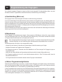
7. Information on Batteries and Rechargeable Batteries
Although use of batteries and rechargeable batteries in everyday life is a matter of course today, there are
many dangers and problems. In particular in LiPo/LiIon batteries with high energy content (as compared to
conventional NiMH batteries), various provisions must be complied with to avoid danger of explosion and
re.
Therefore, always observe the following information and safety notes in handling of batteries and recharge-
able batteries.
• Keepbatteries/rechargeablebatteriesoutofthereachofchildren.
• Donotleaveanybatteries/rechargeablebatterieslyingaroundopenly.Thereisariskofbatteriesbeingswallowed
by children or pets. If swallowed, consult a doctor immediately!
• Removetheightbatteryfromthemodelbeforechargingandputitonre-proofunderground.Keepadistanceto
ammableobjects.
• Neverchargetheightbatteryrightafteruse.AlwaysleavetheLiPoightbatterytocooloffrst(atleast5-10
minutes).
• Onlychargeintactandundamagedbatteries.Iftheouterisolationoftheightbatteryisdamagedortheightbattery
isdeformedorbloated,itmustnotbecharged.Inthiscase,thereisimmediatedangerofreandexplosion!
• Neverdamagetheoutershelloftheightbattery,donotcutthefoilcover,donotpuncturetheightbatterywith
pointedobjects.Thereisariskofreandexplosion!
•Asthechargeraswellastheightbatteryheatupduringthechargingprocess,itisnecessarytoensuresufcient
ventilation.Nevercoverthechargerandightbattery!Ofcourse,thisalsoappliesforallotherchargersandrechar-
geable batteries.
• Chargersmayonlybeoperatedindryrooms.Chargesandightbatteriesmustnotgetdamporwet.
•Neverleavebatteriesunattendedwhilechargingthem.
•Donotexposethechargerorightbatterytohigh/lowtemperaturesortodirectsolarradiation.
•Disconnecttheightbatteryfromthechargerwhenitischargedcompletely.
• Batteries/rechargeablebatteriesmustneverbeshort-circuited,disassembledorthrownintore.Thereisadanger
of explosion!
• Leakingordamagedbatteries/rechargeablebatteriescancausechemicalburnstoskinoncontact;therefore,use
suitable protective gloves.
• Liquidsleakingfrombatteries/rechargeablebatteriesarechemicallyhighlyaggressive.Objectsorsurfacesthat
come into contact with them may take severe damage. Therefore, keep batteries/rechargeable batteries in a suita-
ble location.
• Donotrechargenormal,non-rechargeablebatteries.Thereisariskofreandexplosion!Chargeonlyrechargeable
batteriesintendedforthis;usesuitablechargers.
Batteries (1.5 V) are intended for one-time use only and must be disposed of properly when discharged.

36
• Observecorrectpolaritywheninsertingbatteriesintothetransmitterorconnectingtheightbatterytotheight
controller (positive/+ and negative/-).
Incorrect polarity will damage not only the transmitter but also the plane model and the rechargeable battery. There
isadangerofreandexplosion.
• Ifyoudonotusethemodelforanextendedperiodoftime(e.g.duringstorage)removethebatteries(orrechargeab-
lebatteries)insertedintheremotecontroltoavoiddamagefromleakingbatteries.Alsodisconnecttheightbattery
fromtheightcontroller.
Attention!
Donotleavetherechargeableightbatteryconnectedtotheplanemodelifthelatterisnotused(e.g.during
transportorstorage).Otherwise,theightbatterymaybefullydischargedandisthusdestroyed/unusable!
• Rechargetherechargeablebatteriesaboutevery3months.Otherwise,so-calleddeepdischargemayresult,ren-
dering the rechargeable batteries useless.
• Alwaysreplacetheentiresetofbatteriesorrechargeablebatteriesinthetransmitter.Nevermixfullychargedbat-
teries/rechargeable batteries with partially discharged ones. Always use batteries or rechargeable batteries of the
same type and manufacturer. Never mix batteries and rechargeable batteries!
• WhenhandlingLiPobatteries,observethespecialsafetyinformationofthebatterymanufacturer!
8. Model Setup
Before assembling the model, please read each individual section carefully. The construction stages are
illustrated for better understanding.
For design and colour of your model and the remote control, use the illustration, e.g. on the packaging for
reference.Designandcolourdeviationsintheseoperatinginstructionsarepossible.Theguresinthese
operating instructions only serve illustration.
Only carry out the corresponding steps in the different sections if you have completely understood the
procedure and know exactly what to observe.

37
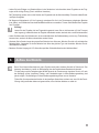
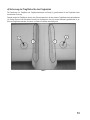
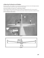
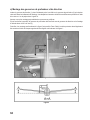
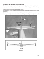
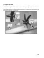
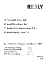
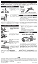
a) Mounting the Elevators and Rudders
Place the rudder (1) in the intended cut-out in the elevator (2) and this unit into the cut-outs at the fuselage. Imprecise
tsshouldbecarefullycorrectedwithacutterknifeand/ornesandpaper.
Also check if installation at an angle of 90° is possible without problems.
When everything is perfect, attach the elevator with the rudder to the fuselage with two M3 x 40 mm screws (3).
Checkifinstallationaccordingtogure2ispossiblewithoutproblems.Ideally,thewingshouldbeinstalledforthisand
thetailunitalignedaccordingtogure1.
Figure 1
Figure 2

38
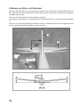
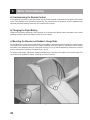
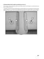
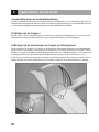
b) Checking the Linkage Rods at the Ailerons
The linkages of the ailerons are pre-installed ex works (1). Also check if the rudder horns of the linkage rods are in the
outer position of the rudder horns (2).
In the neutral position of aileron trimming and control lever, the ailerons need to be in the neutral position as well and
endush(3)withtherearwingedge.Ifthisisnotthecase,theaileronsmustbeadjustedbytwistingtheclevisesin
or out.
The connection of the aileron servos is described in the following chapter „Mounting the Wing“. The correct function is
explained in chapter „Checking the Control Functions“.
Figure 3

39
c) Installing the Wing
The wings are installed in the fuselage slots on the left and right.
For this, push the enclosed wing connector (2) into one wing (1). The wing connector is later secured with one screw
each with the wing pushed on. To install the wing connector, these screws may need to be turned out a little at initial
assembly(seegure5).
Push the wing connector (2) into the hole of the middle fuselage part.
Push the plug of the aileron servo against the counterpiece (3) of the wing holder. The servo plugs match the counter-
piece only in one position. Carefully push the wing half into the cut-out at the fuselage until the shaping of the wing is
ushwiththefuselage.Observethattheservocableisnotcaughtandpushedintothefuselage.
Then install the second wing half on the fuselage in the same manner.
Figure 4

40
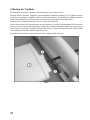
d) Securing the Wings for Flight Operation
Thetsofthewingandwingholderatthefuselage(1)donotensuresufcientfasteningforightoperation.
Therefore, the wings are additionally secured with one screw each that clamps the front wing connectors (2). For
this, carefully turn the screws clockwise until secure clamping is ensured, but the wing connector is not damaged by
too-strong tightening.
Figure 5

41
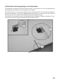
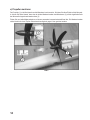
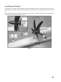
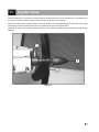
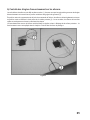
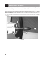
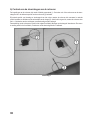
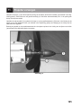
e) Installing the Propeller
The propeller (1) is already correctly installed at the aluminium tappet ex works. Push this unit onto the motor shaft.
Observethatoneofthetwogrubscrewsofthetappet(3)canbescrewedinontheattenedsideofthemotorshaft
(2).
Now tighten both grub screws with a matching hexagon socket wrench. The grub screws should be secured against
coming loose with a drop of threadlocker varnish.
Figure 6

42
9. Motor Commissioning
a) Commissioning the Remote Control
Intheoperatinginstructionsfortheightmodel,onlythecontrolelementsareillustratedintheguresoftheremote
control. They therefore serve illustration purposes only. The precise function of the remote control is explained in the
separately enclosed operating instructions of the remote control system.
b) Charging the Flight Battery
Chargetheightbatteryaccordingtotheinformationofthechargerused.Mostlyobservethesafetynotesinthese
operating instructions and the operating instructions of the charger.
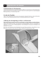
c) Mounting the Elevator and Rudder Linkage Rods
Put the rudder horns of the servos for the elevators and rudders in the neutral position by taking the receiver system
into operation. Also observe the information in chapter „Checking the Control Functions“. Shorten the rods for elevator
and rudder at the dampening areas by twisting the clevises in or out so that the dampening surfaces are in neutral
position and attach the clevises to the rudder horns (1 and 2).
Forelevatorsandrudders,theclevisesshouldbeattachedtotheouterholeoftherudderhornfortherstights.The
correct function is explained in chapter „Checking the Control Functions“.
Figure 7

43
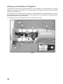
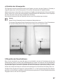
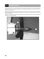
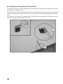
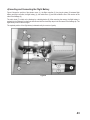
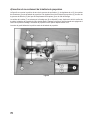
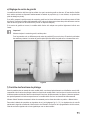
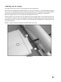
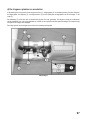
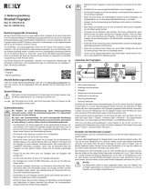
d) Inserting and Connecting the Flight Battery
Figure8showsthepositionoftheelevatorservo(1),theightcontroller(2),theplug-insystem(3)betweenight
batteryandightcontroller,theightbattery(4),therudderservo(5)andtheinstallationsiteofthereceiveratthe
side of the fuselage (6).
Thecabinhood(7)isheldonthefuselagebyalatchingdevice(8).Afterremovingthecanopy,theightbatteryis
pushed into the fuselage from the front and secured with hook-and-loop tape in the front area of the fuselage tip. The
ightbatterymustnotmoveinight.
Therequiredpositionoftheightbatteryisdeterminedbythecentreofgravity.
Figure 8

44
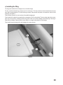
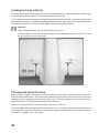
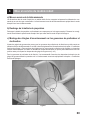
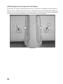
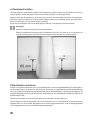
e) Setting the Centre of Gravity
Themodelairplanemustbesetbyproperplacementoftheightbattery(and,ifrequired,byadditionoftrimminglead)
so that the centre of gravity is approx. 65 mm behind the nose strip of the wing.
To do so, mark the corresponding centre of gravity position at the bottom of the wing with a pen. From the bottom, hold
theassembledandready-to-ymodelatthemeasuredpositionswithyourindexngers(oracorrespondingdevice).
If the centre of gravity is set correctly, the model airplane should be leaning slightly forward.
Important!
Always measure the centre of gravity with the cabin hood in place.
Fortherstights,setthecentreofgravityatapprox.62mmwingdepthinsteadofat65mm.Thebest
centre of gravity then can be reset slowly.
Figure 9
f) Checking the Control Functions
Beforestartingyourmodelforthersttime,youneedtofamiliariseyourselfwiththeremotecontrol,thecontrolfunc-
tions and test the model functions. The functions and commissioning of the remote control system can be taken in the
operatinginstructionsseparatelyenclosedwiththeremotecontrol.Thefollowingguresshowtherespectivefunction
symbolically based on a model plane and a remote control transmitter.
Alwaysturnonthetransmitterrstandputthespeedcontrolleverto„Motoroff“.
Connecttheightbatterytotheightcontroller(seegure8,item3).Theightcontrollernowchecksthe„Motoroff“
controlsignalofthetransmitter.Dependingonhowthemotorbrakeisprogrammed,theightcontroller‘sreadiness
for operation is signalled by one or two sounds.

45
Theightcontrollerhasanundervoltagerecognitionthatswitchesoffthemotorataspecicvoltagedepen-
dingonbatterytype.Thusavoidsaharmfuldeepdischargeoftheightbattery.
Theightcontrollerisalreadycorrectlyprogrammedexworks.Formoreinformationonthis,seethechapter
„Programmingtheightcontroller“.
Thesignalsoundsaregeneratedbyashortstart-upofthemotorbytheightcontroller.
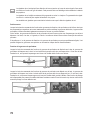
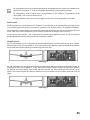
Neutral Position
When the control lever for the rudder, elevator and aileron functions and the respective trimming is precisely in the
centreposition,therudder,elevatorandaileronattheightmodelshouldbepreciselycentred.
Viewedfromtherear,theruddersandelevatorsmustformalevelwiththerudderandmustnotbedeectedtothetop
or bottom, left or right. The ailerons must be at one level with the wings.
If the ailerons and/or rudders or elevators are not aligned precisely, the rudders can be aligned precisely with the
linkage wires by twisting the clevises.
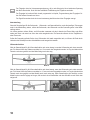
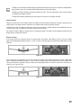
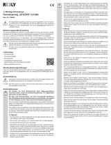
Elevator function
Ifthecontrolstickfortheelevatorfunctionismoveddown,theelevatormustdeecttothetop.Therearrudder
edgemustbedeectedupwardsbyapprox.12mm.Inight,thelandinggearispresseddownwardsandthemodel
ascends.
Figure 10
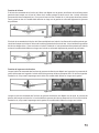
Ifthecontrolstickfortheelevatorfunctionismovedup,theelevatormustdeectdownwards.Therearrudderedge
mustbedeecteddownwardsbyapprox.12mm.Inight,thelandinggearispressedupwardsandthemodeldives.
This control function is required to put the model into a normal light position if it wants to ascend too much due to a
control error or a gust of wind.
Figure 11

46
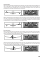
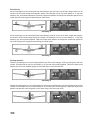
Aileron function
Ifthecontrolleverfortheaileronfunctionismovedtotheleft,theleftwing‘saileronmustbreakouttothetopandthe
aileronoftherightwingtothebottom.Therearrudderedgemustbedeectedordownwardsorupwardsbyapprox.
12mm.Inight,thispressesthewingtothelowerleftandthemodeliestotheleftwithalittleelevatorsupport.
Figure 12
Ifthecontrolleverfortheaileronfunctionismovedtotheright,theleftwing‘saileronmustbreakouttothebottomand
theaileronoftherightwingtothetop.Therearrudderedgemustbedeectedordownwardsorupwardsbyapprox.
12mm.Inight,thispressesthewingtothelowerrightandthemodeliestotherightwithalittleelevatorsupport.
Figure 13
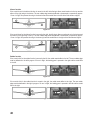
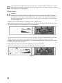
Rudder function
Ifthecontrolstickfortherudderfunctionismovedtotheleft,theruddermustdeecttotheleft.Therearrudderedge
mustbedeectedtotheleftbyapprox.20mm.Inight,thelandinggearispressedtotherightandthemodelies
to the left.
Figure 14
Ifthecontrolstickfortherudderfunctionismovedtotheright,theruddermustdeecttotheright.Therearrudder
edgemustbedeectedtotherightbyapprox.20mm.Inight,thelandinggearispressedtotheleftandthemodel
iestotheright.
Figure 15

47
Iftherudderdoesnotdeectasdescribedabove,the„Servo-Reversefunction“atthetransmittermustbe
used to change the running direction of the servos. Further information on this can be found in the operating
instructions for the remote control.
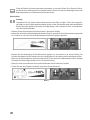
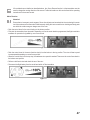
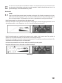
Motor Function
Attention!
Ensurethatnolooseparts,suchaspaper,lmorotherobjectscanbesuckedintotherotorduringthismotor
test. Also make sure that the model is held securely during this test run and that no clothing and body parts
are within the rotation range or danger area of the rotor.
• Pushthecontrolleverforthemotorfunctiontothebottomposition.
• Firststartthetransmitter,thenthemodel.Dependingonhowthemotorbrakeisprogrammed,theightcontroller‘s
readiness for operation is signalled by one or two sounds.
Figure 16
• Pushthecontrolleverforthemotorfunctionslowlyfromthebottomtothetopposition.Therotorwillstartupand
increase speed depending on control lever position.
• Whenthecontrolleverisatthetopstop,themaximumrotorspeedisreached.Thenmovethecontrolleverbackto
the bottom-most position.
• Performabriefmotortestandchecktherunoftherotor.
• Disconnecttheightbatteryfromthemodelandswitchoffthetransmitter.
Figure 17

48
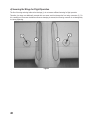
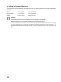
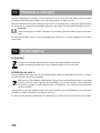
g) Setting the Rudder Deections
Iftheconstructionisperformedandthetransmittersetcorrectly,theruddersshouldhavethefollowingrudderdeec-
tion values:
Aileron 12 mm upwards 12 mm downwards
Elevator rudder 12 mm upwards 12 mm downwards
Rudder 20 mm to the left 20 mm to the right
Attention!
Theindicatedvaluesshowtherudderdeectionstobeselectedfortherstights.
Adjustthedeectionstoyourpersonalpreferencesafterafamiliarisationperiod.
The enclosed remote control system does not permit setting of the servo paths at the transmitter and thus
therudder deectionsatthemodelasmoreexpensivecomputer-basedremote controlsystemsdo.To
changetherudderdeections,thevaluesaresetbyrepositioningthepushrodsontheservoarmsorthe
aps.
Page is loading ...
Page is loading ...
Page is loading ...
Page is loading ...
Page is loading ...
Page is loading ...
Page is loading ...
Page is loading ...
Page is loading ...
Page is loading ...
Page is loading ...
Page is loading ...
Page is loading ...
Page is loading ...
Page is loading ...
Page is loading ...
Page is loading ...
Page is loading ...
Page is loading ...
Page is loading ...
Page is loading ...
Page is loading ...
Page is loading ...
Page is loading ...
Page is loading ...
Page is loading ...
Page is loading ...
Page is loading ...
Page is loading ...
Page is loading ...
Page is loading ...
Page is loading ...
Page is loading ...
Page is loading ...
Page is loading ...
Page is loading ...
Page is loading ...
Page is loading ...
Page is loading ...
Page is loading ...
Page is loading ...
Page is loading ...
Page is loading ...
Page is loading ...
Page is loading ...
Page is loading ...
Page is loading ...
Page is loading ...
Page is loading ...
Page is loading ...
Page is loading ...
Page is loading ...
Page is loading ...
Page is loading ...
Page is loading ...
Page is loading ...
Page is loading ...
Page is loading ...
Page is loading ...
Page is loading ...
Page is loading ...
Page is loading ...
Page is loading ...
Page is loading ...
-
 1
1
-
 2
2
-
 3
3
-
 4
4
-
 5
5
-
 6
6
-
 7
7
-
 8
8
-
 9
9
-
 10
10
-
 11
11
-
 12
12
-
 13
13
-
 14
14
-
 15
15
-
 16
16
-
 17
17
-
 18
18
-
 19
19
-
 20
20
-
 21
21
-
 22
22
-
 23
23
-
 24
24
-
 25
25
-
 26
26
-
 27
27
-
 28
28
-
 29
29
-
 30
30
-
 31
31
-
 32
32
-
 33
33
-
 34
34
-
 35
35
-
 36
36
-
 37
37
-
 38
38
-
 39
39
-
 40
40
-
 41
41
-
 42
42
-
 43
43
-
 44
44
-
 45
45
-
 46
46
-
 47
47
-
 48
48
-
 49
49
-
 50
50
-
 51
51
-
 52
52
-
 53
53
-
 54
54
-
 55
55
-
 56
56
-
 57
57
-
 58
58
-
 59
59
-
 60
60
-
 61
61
-
 62
62
-
 63
63
-
 64
64
-
 65
65
-
 66
66
-
 67
67
-
 68
68
-
 69
69
-
 70
70
-
 71
71
-
 72
72
-
 73
73
-
 74
74
-
 75
75
-
 76
76
-
 77
77
-
 78
78
-
 79
79
-
 80
80
-
 81
81
-
 82
82
-
 83
83
-
 84
84
-
 85
85
-
 86
86
-
 87
87
-
 88
88
-
 89
89
-
 90
90
-
 91
91
-
 92
92
-
 93
93
-
 94
94
-
 95
95
-
 96
96
-
 97
97
-
 98
98
-
 99
99
-
 100
100
-
 101
101
-
 102
102
-
 103
103
-
 104
104
-
 105
105
-
 106
106
-
 107
107
-
 108
108
-
 109
109
-
 110
110
-
 111
111
-
 112
112


Reely 1302975 Operating instructions
- Category
- Remote controlled toys
- Type
- Operating instructions
Ask a question and I''ll find the answer in the document
Finding information in a document is now easier with AI
in other languages
- français: Reely 1302975 Mode d'emploi
- Deutsch: Reely 1302975 Bedienungsanleitung
- Nederlands: Reely 1302975 Handleiding
Related papers
-
 Reely 1542913 Operating instructions
-
Reely 2356861 User manual
-
 Reely 1490800 Operating instructions
-
Reely 2373337 User manual
-
 Reely 1435179 Operating instructions
-
 Reely 1082714 Operating instructions
-
 Reely 1414497 Operating instructions
-
 Reely 1600320 Operating instructions
-
 Reely 1780646 Operating instructions
-
 Reely 239999 Operating instructions


Other documents
-
 RC Logger RC EYE One User manual
-
 Art-Tech Sbach 342 User manual
-
protech TOJEIRO 90 User manual
-
 KYAZHO EDGE 540 User manual
-
ROBBE Air Beaver Instruction And User's Manual
-
Pichler DOMINO 3 User manual
-
-
ParkZone PKZ5275 Owner's manual
-
 Hobbico FLYZONE FREE-FLIGHT F-18 Assembly Instructions
-


