Page is loading ...

R1BK_50-RAD-ING-Manuale-1812.1_SK.3
Installation, Use
and Maintenance Manual
for model
0476
R1BK 50
Floor standing premix condensing
system boiler for outdoor installation

2
R1BK_50-RAD-ING-Manuale-1812.1_SK.3
R1BK 50_SK.3_EN
1. SUMMARY SUMMARY
SUMMARY
INTRODUCTION 4
1. INSTALLER SECTION 7
1.1. INSTALLATION 8
1.1.1. GENERAL INSTALLATION WARNINGS 8
1.1.2. BOILER LOCATION ENVIRONMENTAL REQUIREMENTS 8
1.1.3. REFERENCE LEGISLATION 9
1.1.4. UNPACKING 10
1.1.5. OVERALL DIMENSIONS 11
1.1.6. HEAD/FLOW DIAGRAM 13
1.1.7. INSTALLING THE BOILER 14
1.1.8. HYDRAULIC CONNECTION 15
1.1.9. CHARACTERISTICS OF THE WATER OF THE SYSTEM 16
1.1.10. SYSTEM FILLING 18
1.1.11. CONDENSATE DRAIN 19
1.1.12. ANTI-FREEZE PROTECTION 21
1.1.13. GAS CONNECTION 22
1.1.14. ELECTRICAL CONNECTION 22
1.1.15. POWER SUPPLY 23
1.1.16. OPTIONAL ELECTRICAL CONNECTIONS - INDIVIDUAL INSTALLATION 24
1.1.17. FUME EXHAUST FITTINGS 26
1.1.18. TYPES OF FUME EXHAUST SYSTEMS 27
2. SUPPORT CENTER SECTION 29
2.1. FIRST START-UP 30
2.1.1. PRELIMINARY OPERATIONS FOR FIRST START-UP 30
2.1.2. BOILER COMMISSIONING 31
2.1.3. CO2 VALUE CHECK AND CALIBRATION 32
2.1.4. ACCESSING AND PROGRAMMING THE PARAMETERS 33
2.1.5. DIGITECH CS PARAMETERS TABLE 35
2.1.6. ELECTRIC FAN FREQUENCY/HEAT CAPACITY DIAGRAM 42
2.2. MAINTENANCE 43
2.2.7. GENERAL MAINTENANCE WARNINGS 43
2.2.8. TECHNICAL DATA 44
2.2.9. TECHNICAL ASSEMBLY 47
2.2.10. HYDRAULIC BOARD 48
2.2.11. WIRING DIAGRAM 49
2.2.12. ACCESSING THE BOILER 50
2.2.13. ACCESSING THE ELECTRONIC BOARD 51

3
R1BK_50-RAD-ING-Manuale-1812.1_SK.3
R1BK 50_SK.3_EN
R1BK 50_SK.3_EN
1. SUMMARY SUMMARY
2.2.14. SYSTEM EMPTYING 52
2.2.15. BOILER DEACTIVATION 52
2.2.16. FAULT SIGNALLING CODES 53
2.2.17. ACTIVE FUNCTIONS SIGNALLING CODES 56
2.2.18. GAS CONVERSION 57
3. USER SECTION 59
3.1. USE 60
3.1.1. GENERAL USE WARNINGS 60
3.1.2. CONTROL PANEL 61
3.1.3. DISPLAY ICONS 62
3.1.4. INFO MENU DISPLAY DATA 63
3.1.5. START-UP 64
3.1.6. OPERATING MODE 64
3.1.7. INFORMATIONAL NOTE ON ANTI-FREEZE FUNCTION 65
3.1.8. FAULT SIGNALLING CODES 66
3.1.9. ACTIVE FUNCTIONS SIGNALLING CODES 68
3.1.10. MAINTENANCE 69
3.1.11. COVER CLEANING 69
3.1.12. DISPOSAL 69

4
R1BK_50-RAD-ING-Manuale-1812.1_SK.3
_P refazione_EN
1. INTRODUCTION
INTRODUCTION
WARNING
Before starting any operation it is mandatory to
read this instruction manual, in relation to the
activities to be carried out as described in each
relevant section. Proper operation and optimal
performance of the boiler are ensured by strict
compliance with all the instructions given in this
manual.
The installation, use and maintenance manual is
an integral and essential part of the product and
must be delivered to the user.
MANUAL USERS
The manual users are all those who install, use
and maintain the boiler.
The boiler must be used and accessed only by
qualified operators that fully read and understood
the use and maintenance manual, paying particular
attention to the warnings.
READING AND SYMBOLS OF THE MANUAL
To ease the understanding of this manual,
recurrent symbols where used, in particular:
On the outer margin of the page is placed a thumb
index indicating the type of user to which the
instructions in that section address.
The titles are differentiated by thickness and size
in accordance with their hierarchy.
The images contain important parts described in
the text, marked with numbers or letters.
(See chap “chapter name”): this entry indicates
another section in the Manual that you should
refer to.
Device: this term is used referring to the boiler.
DANGER
It identifies an information related to a
general danger that if not complied with, may cause
serious personal damage or even death.
ATTENTION
It identifies an information that if not
complied with may cause small or medium level
lesions to the person or serious deterioration to the
boiler.
WARNING
It identifies a precaution information that
must be observed in order to avoid damaging the
machine or parts of it.
MANUAL STORAGE
The manual must be carefully stored and replaced
in case of deterioration and/or low legibility.
If you misplace the use and maintenance manual,
you can request it from the Technical Support
Centre giving the serial number and model of the
boiler indicated on the plate placed on the right
side of its casing.
As an alternative, the use and maintenance manual
can be downloaded free from the on-line site www.
radiant.it, accessing the “download” section and
entering the boiler model.
INTRODUCTION

5
R1BK_50-RAD-ING-Manuale-1812.1_SK.3
_P refazione_EN
_P refazione_EN
1. INTRODUCTION
MANUFACTURER WARRANTY AND
RESPONSIBILITY
The warranty of the Manufacturer is provided only
through its own authorized Technical Support
Centres, listed for each Region and Provence on
the site www.radiant.it, and covers all conformity
defects at the moment of sale.
The technical and functional features of the device
are ensured by its use in compliance:
WITH THE USE AND MAINTENANCE
INSTRUCTIONS CONTAINED IN THE MANUALS
ACCOMPANYING THE PRODUCT, THE CONTENT
OF WHICH THE CUSTOMER CERTIFIES THAT HE
IS AWARE;
WITH THE CONDITIONS AND PURPOSES TO
WHICH ASSETS OF THE SAME TYPE ARE
INTENDED.
For more information on the warranty validity,
its duration, the obligations and the exemptions,
please consult the First start-up certificate
attached to this manual.
The manufacturer reserves:
› the right to modify the tools and relative
technical documentation without any obligation
to third parties; neither will the company be
held responsible for any inaccuracies in this
handbook deriving from printing or translation
errors;
› the material and intellectual ownership of
this manual and forbids its distribution and
duplication, even partial, without prior written
authorization.
PRODUCT CONFORMITY
RADIANT BRUCIATORI spa declares that its gas
boilers comply with the European Directives and
with the requirements provided in the European
standards below:
› Eco-design Directive 2009/125 CE,
› Energy labeling Directive 2010/30/CE,
› EU regulation 811/2013,
› EU regulation 813/2013,
› Gas Directive 2016/426/EU,
› Electromagnetic compatibility Directive
2014/30/CE,
› Performance Directive 92/42/CE,
› Low voltage Directive 2014/35/CE.
The materials used such as copper, brass,
stainless steel create a homogeneous, compact
and functional assembly, easy to install and
manage. In its simplicity, the boiler is equipped
with all accessories necessary to render it a
veritable independent heating unit. All boilers
are tested and delivered with a quality certificate
signed by the tester.
INTRODUCTION


The installation operations described in this section should
be performed only by qualified personnel, having the
appropriate technical training in the field for the installation
and maintenance of components of civil and industrial
domestic hot water production and heating plants as
provided by standards and regulations in forced.
1. INSTALLER SECTION1. INSTALLER SECTION

8
R1BK_50-RAD-ING-Manuale-1812.1_SK.3
1 Avvertenze generali per l'installazione_Locale caldaia_cond_alta potenza_EN
1. INSTALLATION
INSTALLER
1.1. INSTALLATION
1.1.1. GENERAL INSTALLATION
WARNINGS
ATTENTION
This machine may be used only for
the purpose for which it has been designed:
heat water to a temperature below boiling
point at atmospheric pressure. Any other
use is considered wrong and dangerous. The
manufacturer is excluded from any contractual
or out of contract responsibility for damage
caused to people, animals or property due to
errors during installation.
ATTENTION
This boiler should be installed only
by qualified personnel, having the appropriate
technical training in the field for the installation
and maintenance of components of civil and
industrial domestic hot water production and
heating plants.
ATTENTION
After having removed the packing,
make sure the equipment is intact. In case of
doubt, do not use the equipment and contact the
supplier.
BEFORE INSTALLING THE BOILER, THE
INSTALLER MUST MAKE SURE THAT THE
FOLLOWING CONDITIONS ARE MET:
› The device is connected to a heating plant and
a water supply network appropriate for its
power and performance.
› The location must be properly vented through
an air vent.
› The air vent must be placed at floor level to
prevent it from being obstructed, protected by
a grid that does not hamper the useful section
of passage.
› The device is suitable for use with the type of
gas available by checking the boiler data plate
(placed on the inner side of the front casing.
› Make sure that the tubes and couplings are
perfectly sealed, without any gas leaks.
› Make sure that the grounding system works
properly.
› Make sure that the electrical systems is
suitable for the maximum power absorbed
by the equipment, value indicated on the data
plate.
WARNING
Use only original RADIANT optional or
kit accessories (including electrical).
1.1.2. BOILER LOCATION
ENVIRONMENTAL
REQUIREMENTS
The boiler has a thermal power over 35 kW and,
therefore, it must be installed only into a heating
unit.
The device's installation location should be vented
due to the presence of threaded joints on the gas
adduction line. The location should be therefore
provided with vents as to ensure air exchange,
with output grid in the natural accumulation area
of eventual gas losses.
WARNING
DO NOT install the boiler in a technical
compartment near a swimming pool or a laundry,
to avoid that the combustion air is exposed to
chlorine, ammonia or alkaline agents that may
worsen the corrosion phenomenon of the heat
exchanger. Failure to observe this caution will
void the warranty of the heat exchanger.
WARNING
If the temperature in the boiler
installation location goes below -10 centigrades,
INSTALLATION

9
R1BK_50-RAD-ING-Manuale-1812.1_SK.3
1 Avvertenze generali per l'installazione_Locale caldaia_cond_alta potenza_EN
1 Avvertenze generali per l'installazione_Locale caldaia_cond_alta potenza_EN
1. INSTALLATION
INSTALLER
please fill the plant with anti-freeze liquid and
insert and electrical resistances kit (see chapter
‘ANTI-FREEZE PROTECTION’).
WARNING
The manufacturer will not be held
responsible for damages caused by incorrect
installation not in conformity with the over
mentioned instructions and not protected
adequately from the freeze.
1.1.3. REFERENCE LEGISLATION
The installation must be realized according to
the requirements of current legislation and in
compliance with local technical regulations,
according to the indications of the good technique.

10
R1BK_50-RAD-ING-Manuale-1812.1_SK.3
1 Disimballo_basamento_R1BK 50_EN
1. INSTALLATION
INSTALLER
1.1.4. UNPACKING
WARNING
Please unpack the boiler just before
installing it. The Company is not responsible for
the damages caused to the device due to incorrect
storage.
WARNING
The packing elements (cardboard box,
wooden crate, nails, fasteners, plastic bags, expanded
polystyrene, etc.) must be kept out of the reach of
children as they may be dangerous. Therefore they
should be dismantled suitably differentiating them in
accordance with the standards in force.
To unpack the boiler, proceed as follows:
› cut the fixing strip (see A-fig.1);
› remove the cardboard box lifting it upwards
(see B-fig.1);
› push the boiler on one side and remove the
pallet underneath (see C-fig.1).
INSTALLATION
fig. 1

11
R1BK_50-RAD-ING-Manuale-1812.1_SK.3
1 Dimensi oni di ingombro_ R1BK 50_ SK .2 _ EN
1 Dimensi oni di ingombro_ R1BK 50_ SK .2 _ EN
1. INSTALLATION
1.1.5. OVERALL DIMENSIONS
LEFT SIDE
AI HEATING FLOW Ø1”1/2
RI HEATING RETURN Ø1”1/2
G GAS Ø3/4”
SC CONDENSATE DRAIN Ø25
E CABLE GLANDS Ø20
S FLUE OUTLET Ø80
130
582
280
264 270
354
SC
EL
RI
AI
495
G
144
S
235 235
480
1455
fig. 1
INSTALLATION

12
R1BK_50-RAD-ING-Manuale-1812.1_SK.3
1 Dimensi oni di ingombro_ R1BK 50_ SK .2 _ EN
1. INSTALLATION
RIGHT SIDE
AI HEATING FLOW Ø1”1/2
RI HEATING RETURN Ø1”1/2
G GAS Ø3/4”
SC CONDENSATE DRAIN Ø25
E CABLE GLANDS Ø20
S FLUE OUTLET Ø80
130
582
280
264 270
354
SC
EL
RI
AI
495
G
144
S
235 235
480
1455
fig. 1
1. INSTALLATION

13
R1BK_50-RAD-ING-Manuale-1812.1_SK.3
1 Diagramma portata-perdita di carico_R1K 50_EN
1 Diagramma portata-perdita di carico_R1K 50_EN
1. INSTALLATION
INSTALLER
1.1.6. HEAD/FLOW DIAGRAM
CIRCULATOR PREVALENCE/FLOW DIAGRAM
BOILER HEAD/FLOW DIAGRAM
Wilo-Yonos PARA RS 15/7.5
0 0,5 1,0 1,5 2,0 2,5 3,0 3,5
0 0,2 0,4 0,6 0,8 1,0
20 4 6 8 10 12 14
0
1
2
3
4
5
6
7
8
0
10
20
30
40
50
60
70
80
0 0,5 1,0 1,5 2,0 2,5 3,0 3,5
4,0
4,0
0
20
40
60
3780/ 25
PWM1
4270/ 15
PWM1
4770/ ≤5
PWM1
3280/ 35
PWM1
2780/ 45
PWM1
2280/ 55
PWM1
1780/ 65
PWM1
1290/ 75
PWM1
max.
p/kPa
H/m
P
1
/W
Q/m³/ h
Q/l/s
Q/Igpm
Q/m³/ h
max.
790/ 85
PWM1
0,0
10,0
20,0
30,0
40,0
50,0
60,0
70,0
0
0,5
1
1,5
2
2,5
[kPa]
[m3/h]
INSTALLATION
fig.1
fig.2

14
R1BK_50-RAD-ING-Manuale-1812.1_SK.3
1 Installazione generatore_R1BK 50_EN
1. INSTALLATION
INSTALLER
1.1.7. INSTALLING THE BOILER
MINIMUM DISTANCES
In order to allow the access inside the boiler for
maintenance operations, you have to respect the
minimum technical spaces indicated in figure 1.
ATTENTION
In boiler installation, follow the
instructions given for installation. Incorrect
slopes of the device would cause the incorrect
flow of condensate through the discharge duct
with the consequent stagnation of condensate
inside the boiler ..
H
A
X Y
INSTALLATION
MINIMUM DISTNACE mm
A - 300 mm
X - 300 mm
Y - 300 mm
H - 1000 mm
fig.1

15
R1BK_50-RAD-ING-Manuale-1812.1_SK.3
1 Allacciamento idraulico_EN
1 Allacciamento idraulico_EN
1. INSTALLATION
INSTALLER
1.1.8. HYDRAULIC CONNECTION
DANGER
Make sure that the tubes of the water
and heating plant are not used as grounding
system for the electrical plant. There are not
suitable for such use.
WARNING
To prevent voiding the warranty and to
ensure the proper operation of the boiler, please
wash the plant (if possible when hot) with suitable
pickling or descaling solutions in order to remove
the impurities coming from tubes and radiators.
WARNING
When connecting the equipment
to water supply, avoid excessive bending and
recovery operations from any off axis positioning
that may damage the tubes causing leaks,
malfunction or early wear.
WARNING
In order to avoid any vibrations and
noises, do not use tubes with small diameters or
elbows with small radius and significant cut-off
of the passage sections.
WARNING
Connect the outlets of safety valves,
three-ways valves (if present) and of the cylinder
(if present) to an outlet funnel, to prevent the
boiler room from flooding if these devices cut
in. This outlet should preferably be sent to the
outside so as to avoid damage to persons or
property caused by hot water in the event that
the valve should open. The manufacturer is not
responsible for any flooding due to the opening of
the safety valve in case of system overpressure.
WARNING
On systems with a closed expansion
tank, the pressure reducer on the automatic
supply unit (where available) should be set to a
pressure that will not exceed the initial design
setting. Make sure that while the equipment is
working the system pressure does not exceed the
working pressure for each component.
WARNING
Ensure that, during the boiler
operation, the system pressure doesn’t exceed
the working pressure of each component.
WARNING
In order to prevent scales or deposits
on the primary heat exchanger, the heating/D.H.W
circuit inlet water must be treated according to
the current regulations.
It is however suggested to treat the water:
› for the heating circuit, over 25 French degrees,
by means of chemical conditioning treatment
for powers < 100 kW or sweetening for powers
> 100 kW.
› for the D.H.W, over 15 French degrees, by means
of chemical conditioning treatment for powers
< 100 kW or sweetening for powers > 100 kW.
It is also necessary to install a safety filter to
protect the system.
WARNING
In case the boiler is installed as part of
a low temperature circuit, please install a safety
thermostat on the heating flow, which can stop
the boiler activity in case of high heating flow
temperature. The company assumes no
liability for damage caused to persons or for failure
to comply with these instructions.
INSTALLATION

16
R1BK_50-RAD-ING-Manuale-1812.1_SK.3
1 Riempimento dell'impianto_MIAH4_R1 K 100_v .2_EN
1. INSTALLATION
INSTALLER
1.1.9. CHARACTERISTICS OF THE
WATER OF THE SYSTEM
For a correct operation of the system, it is
necessary to make sure that:
1. The system does not present losses or that the
most obvious are at least eliminated;
2. If an automatic filling system is present, a litre
meter must be installed in order to precisely know
the extent of any losses;
3. The filling in of the system and the top ups are
performed with softened water in order to reduce
the total hardness. The water must also be treated
in order to maintain the pH within the provided
threshold so as to avoid corrosion phenomena.
4. Either on new systems or on replacements, the
system must be fitted with efficient systems which
ensure the elimination of the air and impurities:
Y filters, micro impurity separators and micro
bubbles of air separators;
5. Avoid draining the water of the system during the
routine maintenance even if it is about apparently
insignificant quantities: for example, in order to
clean the filters, provide the system with adequate
shut-off valves;
6. Always perform an analysis of the water of
the system before opening the communication
between the new generator and the system, in
order to establish if the parameters present in the
water indicate the need to fully drain the system,
to use the water already present in the system or
to chemically wash the system using utility water
adding a detergent when it is suspected that the
system might be dirty or particularly clogged and
at the next loading with new treated water.
Water treatment
In order to preserve the integrity of the water-
fume exchanger and to guarantee optimal thermal
exchanges, it is necessary that the water of the
primary circuit, circulating inside the exchanger
of the condensate boiler, has the characteristics
defined and constant in time. To obtain this, it
is fundamental to perform a series of system
preparation and maintenance operations such as:
• washing the system;
• check the characteristics of the water of the
system;
The type of treatment to be performed will be
chosen based on the characteristics of the water
to treat, of the type of system and on the requested
purity limits
Oxygen
A certain amount of oxygen always enters the
system, both during the filling phase and during
the use in case of reintegration or presence of
hydraulic components without oxygen barriers.
The reaction between the oxygen and the stainless
steel creates corrosion and forms sludge. While
the water fume exchanger is made of stainless
steel, and therefore it is not subject to corrosion,
the sludge created in the carbon steel system
is deposited in the warm points, including the
exchanger. This has the effect to reduce the heat
capacity and thermally insulate the active parts of
the exchanger, which might cause damages.
The precautions to limit the phenomena are:
- Mechanical systems: a deaerator combined with
a sludge remover, correctly installed, reduce the
quantity of oxygen circulating inside the system.
- Chemical systems: the additives allow the oxygen
to dissolve in water.
INSTALLATION

17
R1BK_50-RAD-ING-Manuale-1812.1_SK.3
1 Riempimento dell'impianto_MIAH4_R1 K 100_v .2_EN
1 Riempimento dell'impianto_MIAH4_R1 K 100_v .2_EN
1. INSTALLATION
INSTALLER
Hardness
The filling and make-up water hardness brings
a certain amount of limestone into the system.
It attacks the warm parts of the exchanger, thus
creating load losses and thermal insulation losses
on the active parts. This phenomena can cause
damages.
The filling and make-up water of the system, if
it does not fall under the values indicated below,
should be softened. Moreover, additives can be
added in order to maintain the limestone into
the solution. The hardness must be periodically
checked and registered.
Acidity 7 < pH < 8.5
Conductivity < 400 μs/cm (at 25°C)
Chlorides < 125 mg/l
Iron < 0.5 mg/l
Copper < 0.1 mg/l
If the above indicated limits are exceeded, a water
must be chemically treated.
The type of treatment to be performed will be
chosen based on the characteristics of the water
to treat, of the type of system and on the requested
purity limits.
INSTALLATION

18
R1BK_50-RAD-ING-Manuale-1812.1_SK.3
1 Riempimento dell'impianto_MIAH4_R1 K 100_v .2_EN
1. INSTALLATION
INSTALLER
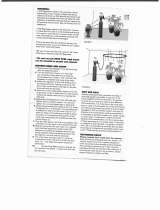
1.1.10. SYSTEM FILLING
WARNING
For system filling use only clean tap
water. In order to prevent limestone build-up and
damages to the domestic water heat exchanger,
the hardness of the domestic supply water
should not exceed 15° Fr. However, please check
the characteristics of the water used and install
suitable treating devices.
WARNING
If the system is filled by adding ethylene
glycol-type chemical agents you have to install on
the loading system a hydraulic trip unit in order
to separate the heating circuit from the domestic
circuit.
Before powering up the boiler, fill the system as
follows:
1. slightly loosen the cap of the jolly valve placed
on the top of the condensing block to release
the air form the top of the system (1-fig.1);
2. check that the jolly valves vent the air present
in the system are not blocked;
3. connect a rubber pipe to the draining tap placed
on top of the condensing heat exchanger (2-
fig.1);
4. open the general domestic water input tap and
load the system by exhaling all the air;
5. use pressure gauge present in the system to
make sure that the system pressure reaches
the design value;
6. after performing this operation, make sure
that the loading tap is properly closed.
7. Open the air relief valves of the radiators and
check the air removal process. When the
water starts to leak close the radiators air
relief valves.
8. If after performing these operations you
observe a decrease of the water pressure
inside the system, open once again the loading
tap until the pressure gauge reaches the
design pressure.
2
1
fig. 1

19
R1BK_50-RAD-ING-Manuale-1812.1_SK.3
1 Scarico condensa_sifone recaplast_EN
1 Scarico condensa_sifone recaplast_EN
1. INSTALLATION
INSTALLER
1.1.11. CONDENSATE DRAIN
FILLING THE CONDENSATE DRAIN SIPHON
Before starting the boiler you have to fill the
condensate collection siphon in order to avoid fuel
reflux through the siphon.
Fill the condensate collection siphon as follows:
› Unscrew the screw “P” (fig. 1), extract the siphon
and fill it with water up to the highest point “T”
(fig. 1);
› Connect the adequately prepared flexible
condensate drain tube to a disposal system
(it is necessary to neutralise the condensate
if the material out of which the canal system
where the condensate arrives is composed
presents a corrosion risk; please see
paragraph ‘CONDENSATE NEUTRALISER’).
The condensate can be drained directly in
the sewerage system by inserting an easily
serviceable siphon.
WARNING
After the first months of operation of the
device, it is recommended to clean the condensate
collection siphon from any deposits deriving
from the first transit of the condensate inside the
technical components of the boiler. Such deposits
might cause a malfunction of the siphon.
CONDENSATE DRAIN
The heat generator produces a significant quantity
of condensate during operation. This condensate
has an acid pH of 3-5. Observe the national standard
in force and the local regulations for the disposal
of the condensate produced by the generator.
The designer, according to the power of the system
and the intended use of the building, is bound to
evaluate the acceptance of systems in order to
neutralise the acid condensate.
The system must be performed so as to avoid the
freezing of the condensate. Before putting into
operation the device, check the correct evacuation
of the condensate.
WARNING
Before connecting the condensate
collection siphon to the drain tube, check that the
slope of the boiler is ensured according to the
indications from chapter ‘INSTALLATION OF THE
GENERATOR’.
WARNING
Correctly connect the condensate
collection siphon of the boiler to a draining system
by adding the slope to the drain of the condensate
of the fume exhaust duct. Where possible, it is
recommended to perform such connection by
means of a collection glass in order to check
the correct discharge of the condensate avoiding
stagnations that might cause dangerous returns of
the condensate to the boiler.
In order to connect the condensate draining to
the draining system, use only corrosion-resistant
materials with an adequate diameter.
T
P
INSTALLATION
fig. 1

20
R1BK_50-RAD-ING-Manuale-1812.1_SK.3
1 Scarico condensa_sifone recaplast_EN
1. INSTALLATION
INSTALLER
CONDENSATE NEUTRALISER
Assemble the condensate neutralisation box, fitted
with granulate and active carbons for a treated
power up to 350 kW (see fig.2). The device allows
neutralising the condensate which is collected
inside the thermal generators and/or in the fume
discharge systems made of stainless steel, plastic,
glass or ceramic.
The acid condensate, inserted into the
neutralisation box, follows a mandatory path for
two phases; the first one, filtration of nitrates and
sulphates by means of active carbons contained
in the first tube line, in the second one, the pH is
increased.
The acidity of the condensate can be checked
by using litmus paper in order to determine the
pH. Then, the neutralised condensate can be
transported into the sewage system.
MAINTENANCE
The pH parameters must be comprised between
< 7 and 8.5 >.
Every six months, it is necessary to establish the
PH of the treated condensate inside the neutraliser.
Immerse a litmus paper (or a suitable digital
tool) in the condensate near the tapped draining
connection for about 2 seconds and thus lay it on a
white paper. After about 30 seconds, it is possible
to compare with the coloured scale. The neutral
point is on the value 6.8-7; at a lower value, the
condensate is acid, at a higher value, it is base].
If necessary, replace the active carbon and the
reagent granulate.
cod.: 82153LA
INSTALLATION
fig. 2
CONDENSATE
COLLECTION HOLE
SULPHATE
ACTIVE CARBONS
SEAT TUBE
CARBONS
OUTPUT CONNECTION
NEUTRALISED CONDENSATE
/