Page is loading ...

Crestron Green Light Express™ Dimming Panel
Introduction
Crestron Green Light Express™ dimming panels come pre-configured with GLXX-2DIM8 dimming modules
already installed. The cabinets only require installation and wiring of feed and load circuits.
Application
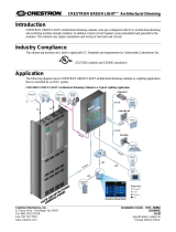
The following diagram shows Crestron Green Light Express dimming panels in a lighting application that is
controlled by an IPAC system.
Crestron Green Light Express Dimming Panels in a Typical Lighting Application
C
R
E
S
N
E
T
O
V
E
R
R
I
D
E
C
R
E
S
N
E
T
C
O
N
T
R
O
L
C
R
E
S
N
E
T
Crestron Electronics, Inc. Installation Guide – DOC. 6889B
15 Volvo Drive Rockleigh, NJ 07647 (2025420)
Tel: 888.CRESTRON 09.10
Fax: 201.767.7576 Specifications subject to
www.crestron.com change without notice.

Dimming Panel Crestron Green Light Express™
Regulatory Compliance
This product is Listed to applicable UL Standards and requirements by Underwriters Laboratories Inc.
Federal Communications Commission (FCC) Compliance Statement
This device complies with part 15 of the FCC Rules. Operation is subject to the following conditions:
(1) This device may not cause harmful interference and (2) this device must accept any interference received,
including interference that may cause undesired operation.
CAUTION: Changes or modifications not expressly approved by the manufacturer responsible for compliance
could void the user’s authority to operate the equipment.
NOTE: This equipment has been tested and found to comply with the limits for a Class B digital device,
pursuant to part 15 of the FCC Rules. These limits are designed to provide reasonable protection against harmful
interference in a residential installation. This equipment generates, uses and can radiate radio frequency energy
and, if not installed and used in accordance with the instructions, may cause harmful interference to radio
communications. However, there is no guarantee that interference will not occur in a particular installation. If
this equipment does cause harmful interference to radio or television reception, which can be determined by
turning the equipment off and on, the user is encouraged to try to correct the interference by one or more of the
following measures:
Reorient or relocate the receiving antenna
Increase the separation between the equipment and receiver
Connect the equipment into an outlet on a circuit different from that to which the receiver is connected
Consult the dealer or an experienced radio/TV technician for help
This Class B digital apparatus complies with Canadian ICES-003.
Cet appareil numérique de la classe B est conforme à la norme NMB-003 du Canada.
Industry Canada (IC) Compliance Statement
As of the date of manufacture, the Green Light Express Dimming Panel has been tested and found to comply
with specifications for CE marking and standards per EMC and Radiocommunications Compliance Labelling.
2 • Crestron Green Light Express™ Dimming Panel Installation Guide – DOC. 6889B

Crestron Green Light Express™ Dimming Panel
Physical Description
This section shows the dimensions of the Crestron Green Light Express dimming panels.
Dimensions of GLPX-XDIM-FT-8 Dimming Panels (Front, Side and Bottom View)
14 1/8"
(359 mm)
12 5/16"
(313 mm)
14 1/8"
(359 mm)
3 1/4"
(83 mm)
1 5/16"
(34 mm)
2 15/16"
(75 mm)
1 3/8"
(35 mm)
4 3/8"
(111 mm)
2 15/16"
(75 mm)
1 3/8"
(35 mm)
1/8"
(4 mm)
1 5/16"
(34 mm)
3 9/16"
(91 mm)
Installation Guide – DOC. 6889B Crestron Green Light Express™ Dimming Panel • 3

Dimming Panel Crestron Green Light Express™
Dimensions of GLPX-XDIM-FT-8 Dimming Panels (Internal View)
12 1/8"
(309 mm)
12 "
(305 mm)
(4X) Ø 1/4"
(Ø 7 mm)
MOUNTING HOLES
10 "
(254 mm)
1 1/16"
(27 mm)
GROUND
BUS
4 • Crestron Green Light Express™ Dimming Panel Installation Guide – DOC. 6889B

Crestron Green Light Express™ Dimming Panel
Dimensions of GLPX-XDIM-FT-16 Dimming Panels (Front, Side and Bottom View)
24 1/4"
(616 mm)
16 1/8”
(409 mm)
3 1/16”
(78 mm)
KNOCKOUT FOR 3/4”
(20 mm) CONDUIT
(TYPICAL BOTH
SIDES)
4 7/16”
(113 mm)
1/4” (7 mm)
3 1/4”
(83 mm)
2 1/2” (64 mm)
14 3/8"
(365 mm)
1 1/4” (32 mm)
Installation Guide – DOC. 6889B Crestron Green Light Express™ Dimming Panel • 5

Dimming Panel Crestron Green Light Express™
Dimensions of GLPX-XDIM-FT-16 Dimming Panels (Internal View)
23 1/2"
(597 mm)
18 15/16”
(481 mm)
(2X) Ø 7/16 ( 12 )
MOUNTING HOLES
Ømm
(2x) 11/16”
(19 mm)
2 1/8” (55 mm)
(2x) Ø 5/8”
(Ø 16 mm)
(2X) Ø 5/16”
(Ø 8 mm)
MOUNTING HOLES
2 1/4”
(58 mm)
10 7/8”
(276 mm)
* TIE WRAP
HOLDERS (MAY
BE MOVED TO
OTHER HOLES
A
S REQUIRED)
SERVICE
SCREWDRIVER
* Installed GLXX-2DIM8 modules come with additional tie wrap holders.
6 • Crestron Green Light Express™ Dimming Panel Installation Guide – DOC. 6889B

Crestron Green Light Express™ Dimming Panel
Dimensions of GLPX-XDIM-FT-24 Dimming Panels (Front, Side and Bottom View)
16 1/8”
(409 mm)
39 5/8”
(1 m)
3 1/16”
(78 mm)
KNOCKOUT FOR 3/4”
(20 mm) CONDUIT
(TYPICAL BOTH
SIDES)
4 7/16”
(113 mm)
1/4” (7 mm)
3 1/4”
(83 mm)
2 1/2” (64 mm)
14 3/8"
(365 mm)
1 1/4” (32 mm)
Installation Guide – DOC. 6889B Crestron Green Light Express™ Dimming Panel • 7

Dimming Panel Crestron Green Light Express™
Dimensions of GLPX-XDIM-FT-24 Dimming Panels (Internal View)
2 1/8” (55 mm)
(2X) Ø 5/16”
(Ø 8 mm)
MOUNTING HOLES
(2x) 11/16”
(19 mm)
10 7/8”
(276 mm)
2 1/4”
(58 mm)
GROUND
LUG
38 7/8”
(998 mm)
34 3/8”
(873 mm)
(2X) Ø 7/16
(Ø 12 mm)
MOUNTING HOLES
(2x) Ø 5/8”
(Ø 16 mm)
* TIE WRAP
HOLDERS (MAY
BE MOVED TO
OTHER HOLES
AS REQUIRED)
SERVICE
SCREWDRIVER
* Installed GLXX-2DIM8 modules come with additional tie wrap holders.
8 • Crestron Green Light Express™ Dimming Panel Installation Guide – DOC. 6889B

Crestron Green Light Express™ Dimming Panel
Installation
Observe the following when installing the panel:
• The panel must be mounted by a licensed electrician in accordance with all national and local codes. Refer
to the diagram below for specific requirements.
• The panel is designed for surface mounting on a wall.
• Panels are intended for indoor use only.
• The ambient temperature range should be 32°F to 104°F (0°C to 40°C). The relative humidity should range
from 10% to 90% (non-condensing). Allow adequate clearance in front of the cover for servicing.
Mounting Location
3 ft
(0.9 m)
Minimum
Required
Clearance
Wall
Installation Guide – DOC. 6889B Crestron Green Light Express™ Dimming Panel • 9

Dimming Panel Crestron Green Light Express™
Wiring
NOTE: All wiring must be installed in accordance with all local and national electrical codes.
NOTE: Refer to the torque settings specified on pages 11 and 12.
Crestron Green Light Express dimming panels are shipped with GLXX-2DIM8 dimming modules installed. The
following must be performed after mounting the panel:
• Connect incoming feed conductors to the input terminals and connect loads to output terminals (section A
of the following diagram)
• Connect control wiring (section B of the following diagram)
SERVICE
SCREWDRIVER
A
B
CLASS 2
WIRING ONLY
FEEDS
FROM
BREAKER
PANEL
TO
LOADS
FEEDS
FROM
BREAKER
PANEL
TO
LOADS
10 • Crestron Green Light Express™ Dimming Panel Installation Guide – DOC. 6889B

Crestron Green Light Express™ Dimming Panel
Feed-Through and Load Wiring (Section A)
NOTE: Use copper conductors only – rated 75°C.
Wire Gauge and Torque Values
TERMINAL CONNECTOR MAX
WIRE RANGE
TORQUE STRIP
LENGTH
INPUTS 26-10 AWG 5.31 lb-in (0.6 Nm) to
7.08 lb-in (0.8 Nm) max
3/8”
(9 mm)
OUTPUTS 26-10 AWG 5.31 lb-in (0.6 Nm) to
7.08 lb-in (0.8 Nm) max
3/8”
(9 mm)
GROUND LUG 14-4 AWG 25-45 lb-in
(2.8-5.1 Nm)
3/4"
(19 mm)
Load Wiring for GLXX-2DIM8
}
NEUTRAL
L1
N1
BRANCH
BREAKER
NEUTRAL
L2
N2
BRANCH
BREAKER
DM1
DM2
DM3
DM4
DM5
DM6
DM7
DM8
TO LOADS
TO LOADS
}
NOTE: All GLXX-2DIM8 modules must be connected together via the NET ports.
Installation Guide – DOC. 6889B Crestron Green Light Express™ Dimming Panel • 11

Dimming Panel Crestron Green Light Express™
Control Wiring (Section B)
The bottom of the cabinet contains Cresnet
®
connections for interfacing to the rest of the Crestron
®
control system.
It also provides overrides input which can be tied to devices such as the GLS-PLS-120/277 phase-loss sensor, or
other devices that provide a dry contact closure (manual switch, fire alarm relay, etc.).
To ensure optimum performance over the full range of your installation topology, use Crestron certified wire.
Failure to do so may incur additional charges if support is required to identify performance deficiencies because of
using improper wire.
NOTE: Interface connectors for NET (x4), and OVERRIDE (x3) ports are provided.
Wire Gauge and Torque Values
TERMINAL CONNECTOR MAX
WIRE RANGE
TORQUE STRIP
LENGTH
NET 26-12 AWG
4.43 lb-in
(0.5 Nm)
1/4”
(6 mm)
OVERRIDE 26-12 AWG
4.43 lb-in
(0.5 Nm)
1/4”
(6 mm)
Connector Wiring
NET:
TO CONTROL SYSTEM AND
OTHER CRESNET DEVICES
OVERRIDE:
FROM GLS-PLS-120/277, FROM
OTHER CABINET,
FROM ALARM, ETC.
(OPTIONAL); TO OTHER
CABINET(S) IF NECESSARY
RED
WHITE
BLUE
BLACK
RED
WHITE
BLUE
BLACK
MODULES:
TO GLXX-2DIM8
MODULES (PREWIRED)
NOTE: For instructions on network wiring, refer to “Appendix C: Network Wiring” on page 21.
12 • Crestron Green Light Express™ Dimming Panel Installation Guide – DOC. 6889B

Crestron Green Light Express™ Dimming Panel
NET Port Wiring
When wiring the supplied NET connectors for connection to a Crestron control system or other device on the
Cresnet network, use Crestron certified wire such as CRESNET-NP or CRESNET-P. For instructions on
network wiring, refer to “Appendix C: Network Wiring” on page 21.
When daisy-chaining connections between NET ports, strip the ends of the wires carefully to avoid nicking the
conductors. Twist together the ends of the wires that share a pin on the network connector, insert the connection
into the Cresnet connector, tighten the retaining screw. Repeat the procedure for the other three conductors.
OVERRIDE Port Wiring
When a connection is applied between the override terminals, the modules will enter Override mode. The
Crestron GLS-PLS-120/277 phase-loss sensor or any device that provides a dry contact closure can be
connected to the supplied OVERRIDE connector on the bottom of the cabinet.
Installation Guide – DOC. 6889B Crestron Green Light Express™ Dimming Panel • 13

Dimming Panel Crestron Green Light Express™
Testing
Manual Load Control
Lighting loads can be manually controlled from the front panel. To dim or turn a load on or off, press the channel
button corresponding to the desired load. When a load is switched on, the status LED of the channel will illuminate
and the display on the GLXX-2DIM8 will indicate the current lighting level of the load.
GLXX-2DIM8 Channel Control (Channel 1 is shown)
STATUS LED (GREEN)
CHANNEL NUMBER
CHANNEL BUTTON
Manual Load Configuration
By default, all channels are set for dimmer operation. The 3-way slide switches provided on the GLXX-2DIM8
allows the user to manually configure each channel for either dimmer, 3-wire fluorescent or non-dimmer operation.
3-way Slide Switch
{
SLIDE SWITCH
When a channel pair is set to 3-wire fluorescent, the channel button corresponding to the first channel in the pair will
control dimming functionality. The button corresponding to the second channel in the pair will be disabled. The
status LED’s for both channels will operate in tandem.
14 • Crestron Green Light Express™ Dimming Panel Installation Guide – DOC. 6889B

Crestron Green Light Express™ Dimming Panel
2-Wire Dimmable or Non-Dimmable Operation
Connect wiring for 2-wire dimmable or non-dimmable operation as shown below. Set channel dip switches to DIM
or NON-DIM as required.
Wiring for 2-Wire Dimmable or Non-Dimmable Loads
DM1
L1
N1
N
H
LOAD
SET CHANNEL DIP
SWITCH TO OR
AS REQUIRED
DIM
NON-DIM
L
BRANCH BREAKER
TO NEUTRAL BUS
TO NEUTRAL BUS
Installation Guide – DOC. 6889B Crestron Green Light Express™ Dimming Panel • 15

Dimming Panel Crestron Green Light Express™
3-Wire Fluorescent Ballast Operation
Connect wiring for 3-wire fluorescent operation as shown below. The first channel in the pair will act as the
dimming control (1-100%). The second channel in the pair will provide full switched power according to the state of
the first channel. Set both channel dip switches in the pair to 3 WIRE FL.
Wiring for 3-Wire Fluorescent Loads
DM1
L1
N1
3-WIRE
FLUORESCENT
LOAD
DM2
SET BOTH CHANNELS
IN PAIR TO
3-WIRE FL
N
DH
SH
L
BRANCH BREAKER
TO NEUTRAL BUS
TO NEUTRAL BUS
16 • Crestron Green Light Express™ Dimming Panel Installation Guide – DOC. 6889B

Crestron Green Light Express™ Dimming Panel
Override Mode
The Override mode overrides the control system program and sets all of the output states to the stored override
values. For instructions on saving override settings, refer to “Save Override Settings” below.
To enable Override mode, press and release the OVR button. The OVR LED flashes slowly.
NOTE: If the Override mode was enabled from an external device (i.e. a contact closure is present on the
OVERRIDE terminals), the OVR LED will flash quickly. Pressing the OVR button has no effect.
To disable Override mode, press the OVR button again. The OVR LED extinguishes and the outputs return to the
states set by the control system program.
NOTE: If override states have not been stored, the factory default override state is all loads on.
Save Override Settings
The state of each output can be saved as an override setting, which can be automatically recalled when the Override
mode is enabled.
NOTE: The control system program has a setting that can prevent locally saving the override state. If this setting is
enabled, the display shows “Er” when trying to save override states. For more information, refer to the SIMPL
Windows help file.
To save the states of all outputs as the override setting, press and hold the OVR button for three seconds until the
OVR LED blinks once.
System Operation and Commissioning
This cabinet has been designed as a component of a programmed Crestron system. System commissioning by an
authorized Crestron representative
must be performed to ensure system operation.
Once the cabinet has been wired and the modules have been tested, contact Crestron at 1-888-CRESTRON
[1-888-273-7876] to schedule commissioning.
Installation Guide – DOC. 6889B Crestron Green Light Express™ Dimming Panel • 17

Dimming Panel Crestron Green Light Express™
Problem Solving
Troubleshooting
The following table provides corrective action for possible trouble situations. If further assistance is required, please
contact a Crestron customer service representative.
Troubleshooting
TROUBLE POSSIBLE CAUSE(S) CORRECTIVE ACTION
Device is not receiving
power from a Crestron
power source.
Use the provided Crestron power source.
Verify connections.
Device is not receiving
sufficient power via
Cresnet link.
Use the Crestron Power Calculator to help
calculate how much power is needed for
the system.
Module(s) does not
function.
System commissioning
not complete.
Arrange for system commissioning.
Unit cannot be taken out
of Override mode
Short (contact closure)
exists between G and OVR
terminals on any of the
OVERRIDE terminals
present at bottom of the
cabinet.
Determine the reason for the short.
Remove or remedy the short
(e.g. GLS-PLS-120/277 phase-loss sensor
may not have been installed properly, or
actual phase-loss has been detected).
Further Inquiries
If you cannot locate specific information or have questions after reviewing this guide, please take advantage of
Crestron's award winning customer service team by calling Crestron at 1-888-CRESTRON [1-888-273-7876].
You can also log onto the online help section of the Crestron website (
www.crestron.com/onlinehelp) to ask
questions about Crestron products. First-time users will need to establish a user account to fully benefit from all
available features.
18 • Crestron Green Light Express™ Dimming Panel Installation Guide – DOC. 6889B

Crestron Green Light Express™ Dimming Panel
Appendix A: Setting Module Net IDs
The following procedure will normally be performed by an authorized Crestron representative as part of the System
Commissioning phase. For system wiring and basic testing as described on pages 10 and 14, it is not necessary to
perform this step. Only perform this step if instructed by an authorized Crestron representative, or when replacing
modules on a system that have already been commissioned (in the latter case the Net ID should be set to match the
Net ID of the module being replaced).
The Net ID of each module in the cabinet can be changed from the front panel of each module. The Net IDs of each
module in the system must be unique.
To set the Net ID using the front panel:
1. Press the recessed SETUP button to enter the Setup mode. The SETUP LED illuminates.
2. As shown in the following diagram, press the left button under the NET ID display to change the left digit
of the Net ID or press the right button under the NET ID display to change the right digit of the Net ID
number.
Changing the Net ID
CHANGES
LEFT DIGIT
CHANGES
RIGHT DIGIT
LABEL FOR
NET ID
SETUP
BUTTON & LED
RIGHT DIGITLEFT DIGIT
3. When the desired Net ID is displayed, press the SETUP button to exit the Setup mode. The SETUP LED
extinguishes.
If the SETUP button is not pressed, the Setup mode will time out after one minute of inactivity and the Net
ID will revert back to its original value.
Installation Guide – DOC. 6889B Crestron Green Light Express™ Dimming Panel • 19

Dimming Panel Crestron Green Light Express™
Appendix B: Specifications
Specifications for the GLXX-2DIM8 modules are listed in the following table.
GLXX-2DIM8 Module Specifications
SPECIFICATION DETAILS
Input Voltage 100 – 277 VAC 50/60 Hz
Supported Load
Types
Incandescent, HID, magnetic low voltage (MLV), electronic low voltage* (ELV),
neon/cold cathode, and fluorescent ballasts, motor
Maximum Load
Lighting 16 A per output (16A max total for group 1-4 and 16A max total for group 5-8)
Motor
1 hp @ 120V
2 hp @ 230V/277V
Environmental
Temperature
32º to 104º F (0º to 40º C)
Humidity 10% to 90% RH (non-condensing)
Heat Dissipation 154 BTU/HR
Cresnet Power
Usage
5W
* Forward phase or leading edge compatible transformers only.
20 • Crestron Green Light Express™ Dimming Panel Installation Guide – DOC. 6889B
/