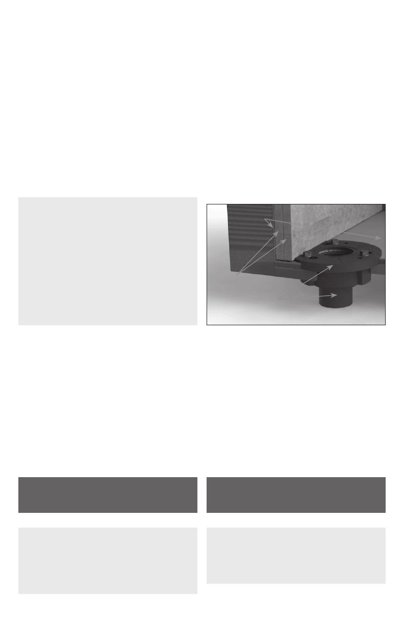
Infinity Drain GJC 38 Operating instructions

Type
Operating instructions
PVC Channel
Site Sizable Series
Installation Instructions
The Site Sizeable Series intended for use with traditional waterproong methods:
°
Hot Mop
°
Copper Pan
°
Rubber Liner (Chloraloy®)
°
PVC Liner
°
Lead Pan
°
Fiberglass
Dimension are subject to Manufacturers tolerance and change without notice. We can assume no responsibility for
use of superseded or void data.
Las dimensiones están sujetos a la tolerancia del fabricante y cambio sin previo aviso. No podemos asumir ninguna
responsabilidad por el uso de datos a sustituir los nulos.
S-TIF 6540
S-TIF 6548
S-TIF 6560
S-TIF 6580
S-TIF 6596
S-TIF 65
S-AG 3836
S-AG 3848
S-AG 3860
S-AG 3896
S-AG 38
S-AG 10048
S-AG 10096
S-AG 100
S-DG 3848
S-DG 3860
S-DG 3896
S-DG 38
S-DG 6548
S-DG 6560
S-DG 6596
S-DG 65
S-AG 6536
S-AG 6548
S-AG 6560
S-AG 6596
S-AG 65
Infinity Drain18 Secatoag Avenue, Port Washington, New York 11050
Phone 516.767.6786 Fax 516.740.3066 www.InfinityDrain.com
Made in the U.S.A.
2
S-AG 38 Series
A 3836 36″ Stainless Steel Grate
A 3848 48″ Stainless Steel Grate
A 3860 60″ Stainless Steel Grate
G 3836 36″ PVC Channel
G 3848 48″ PVC Channel
G 3860 60″ PVC Channel
G 3896 96″ PVC Channel
E 38 PVC Stop End
S 32 PVC Outlet Section
S 50 PVC Threaded Outlet
S-DG 65 Series
D 6548 48″ Stainless Steel Grate
D 6560 60″ Stainless Steel Grate
G 6548 48″ PVC Channel
G 6560 60″ PVC Channel
G 6596 96″ PVC Channel
E 65 PVC Stop End
S 50 PVC Threaded Outlet
S-AG 100 Series
A 10048 48″ Stainless Steel Grate
G 10048 48″ PVC Channel
G 10096 96″ PVC Channel
E 100 PVC Stop End
S 50 PVC Threaded Outlet
S-DG 38 Series
D 3848 48″ Stainless Steel Grate
D 3860 60″ Stainless Steel Grate
G 3848 48″ PVC Channel
G 3860 60″ PVC Channel
G 3896 96″ PVC Channel
E 38 PVC Stop End
S 32 PVC Outlet Section
S 50 PVC Threaded Outlet
S-AG 65 Series
A 6536 36″ Stainless Steel Grate
A 6548 48″ Stainless Steel Grate
A 6560 60″ Stainless Steel Grate
G 6536 36″ PVC Channel
G 6548 48″ PVC Channel
G 6560 60″ PVC Channel
G 6596 96″ PVC Channel
E 65 PVC Stop End
S 50 PVC Threaded Outlet
S-TIF 65 Series
TA 6540 40″ Stainless Steel Grate
TA 6548 48″ Stainless Steel Grate
TA 6560 60″ Stainless Steel Grate
G 6540 40″ PVC Channel
G 6548 48″ PVC Channel
G 6560 60″ PVC Channel
G 6580 80″ PVC Channel
G 6596 96″ PVC Channel
E 65 PVC Stop End
S 50 PVC Threaded Nipple
TIF PL TIF Plates
TKEY Lift Out Key
Series Components:
Note: Installer must verify
all rough-in dimensions
prior to installation and
consult local and national
codes. Conformity and com-
pliance to local and national
codes are the responsibility
of the installer.
Tenga en cuenta: Instala-
dor debe comprobar todas
las dimensiones en las par-
tes previa a la instalacn
y consultar localmente y
nacionalmente los códigos.
La conformidad y el cum-
plimiento de códigos local
y nacional es responsabili-
dad del instalador.
*Not provided by Innity Drain kits
KEY
(A) Top Grate –
A38/D38/A65/TA65/A100
(B) PVC Channel –
G38/G65/G100
(C) Stop End – E38/E65/E100
(D) Outlet Section – S32
(Not Applicable for
AG65/DG65/TIF65/AG100)
(E) Threaded Nipple - S50
(F65 – non-threaded
nipple, for no-hub
installation)
Weep Holes
Waterproong Membrane
(F) 2” Throat Clamp Down
Drain Body*
(Two Pieces)
(F1)
(F2)
3
S-AG38/S-DG38/S-AG65/S-DG65/S-AG100/S-
TIF65 kits DO NOT include a mechanically
fastening clamp down drain due to the disparity
of material of each consumers existing plumbing.
This is a standard item that is available through
Innity Drain or your local plumbing supply from
various manufacturers (Oatey®, Sioux Chief™,
JSC™, PROFLO™, Matco-Norca™).
S-AG 38/S-DG38/S-AG65/S-DG65/S-AG100/
S-TIF65 NO INCLUYE la sujeción mecánica
del drenaje por la razón que varía el material
de código local. Este drenaje es residencial
que está disponible a través de Innity Drain
o su local suministro de plomería de diversos
fabricantes. (i.e. Oatey®, Sioux Chief™, JSC™,
PROFLO™, Matco-Norca™).
2” clamp down drain
not included in kit
Add Clamp Down Drain:
CDA 22 Clamp Down Drain ABS
CDI 22 Clamp Down Drain Cast Iron
CDP 22 Clamp Down Drain PVC
Optional Components: (Not Included)
F 65 PVC Non-Threaded Outlet GAM 65 PVC 90° Angle Joiner TNRN-P PVC Threaded Nipple
F 100 PVC Non-Threaded Outlet G38108 108” PVC Channel UCP 2 Universal 2” Clamping Plate
GJC 38 PVC Straight Joiner Strip G65108 108” PVC Channel UCP 4 Universal 4” Clamping Plate
GAM 38 PVC 90° Angle Joiner GJ 100 PVC Straight Joiner Strip ERB Eccentric Reducer Bushing 4”x2
GJC 65 PVC Straight Joiner Strip GA 100 PVC 90° Angle Joiner
Section A-A
S-AG 38, S-DG 38
1⅝"
1⅞"
³ ¹"
2½"
6½"
2"
Section A-A
S-TIF 65
1¾"
¾"
2⅞"
1⁹ ¹"
2½"
6½"
2"
Section A-A
S-AG 65, S-DG 65
2½"
2⅞"
6½"
2"
¹ ¹"
1⅝"
1¾"
4³⁄¹⁶"
¹³⁄ ¹⁶"
2½"
6½"
2"
Section A-A
S-AG 100
All drains can be
adjusted upward
for an additional
1” in height.
4
OPTIONAL PROCEDURE:
When drain install is required to be ush
against the nished wall, build out wall with
backer board over round clamp down drain
body (F) to compensate for the drain radius.
PROCEDIMIENTO OPCIONAL:
Cuando el drenaje sea instalado, se requi-
ere que esté completamente a la pared,
construir la pared con múltiples paneles de
cemento sobre el redondo drenaje (F) para
compensar el radial del drenaje.
Installation
1. Determine the location of the drain outlet
location. Typically linear drains span a dimen-
sion from wall to wall, against a wall or at a
shower entrance.
2. If clamp down drain body (F) is not
installed. Attach (F) to existing waste line
and allow drain body to recess into sub-
floor. Ensure that drain body (F) is level.
Unscrew and remove top clamp down plate
from drain body.
3. Spread a primary mortar bed across the
intended shower area. Pitch this bed in four
directions towards the drain body (F).
4. When mortar layer is dry, perform
necessary waterproong (PVC Liner, CPE
Rubber Liner/Chloraloy™, Lead Pan, Copper
Pan, Hot Mop, Fiberglass) as per local code.
Ensure waterproong layer reaches the
edge of the hole in the drain body (F). Reat-
tach the top clamp down plate to the clamp
down drain body (F) over the waterproong
layer using bolts.
5. Measure desired wall to wall length, allow
for wall tile thickness and 3/16” for both stop
ends (C). Cut PVC channel (B) to desired length.
Instalación
1. Determine la ubicación del emplazamiento
del drenaje. Típicamente el drenaje lineal atra-
viesa una dimensn de pared a pared, contra
la pared, o en una entrada de un baño.
2. Si el drenaje (F) no está instalado. Adjuntar
el drenaje (F) a la línea de residuos exis-
tentes y permite el drenaje a que descanse
en el piso. Asegúrese, que el drenaje (F) este
nivelado. Destornilla y remueve la placa de
sujecn de arriba.
3. Esparcir una primaria de capa de mortero a
través del destino o zona del bo. Lanzar la
capa de mortero en cuatro direcciones hacia
el drenaje (F).
4. Cuando la capa de mortero este seca, realice
la impermeabilización necesaria (Forro del PVC,
cobre, panal de vidrio) según el código local.
Asegura que la capa de impermeabilización
alcance al borde del agujero en el drenaje (F).
Vuelva a colocar la placa de sujecn de arriba
al drenaje (F) sobre las capa de impermeabili-
zación usando tonillos.
5. Medir la longitud deseada a pared a pared,
permitir el espesor de la baldosa pared y
3/16” por ambas partes (C). Corte canal (B) a
la desead longitud.
TENER EN CUENTA SOLO PARA S-AG38/S-
DG38: Tener en cuenta en los dos 7/16”
sección (D) a lo largo del canal.
NOTE ONLY FOR S-AG38/S-DG38 Series:
Account for the 2-7/16” outlet section (D)
along channel length.
6a. ONLY FOR S-AG38/S-DG38 Install: Cut the
sized PVC channel at the desired location of the
outlet section. Insert the open ends of the PVC
channel (B) into the slotted ends of the outlet
section (D) Dry t components before axing.
Ax with clear PVC primer and PVC cement.
6a. SOLO PARA S-AG38/S-DG38 INSTALA-
CION: Corte el canal de PVC a la ubicación
deseada a donde va ser la sección de salida
de agua. Pegar la parte (D) a la parte (B) del
canal con PVC cemento.
Waterproong
Membrane
Double Layer Backer Board
(F) 2” Throat Clamp Down
Drain Body* (Two Pieces)
(F1)
(F2)
*Not provided by Innity Drain kits
OPTIONAL PROCEDURE / PROCEDIMIENTO OPCIONAL
5
6b. ONLY FOR S-AG65/S-DG65/S-TIF65/S-
AG100 Install: Using a 2-1/4” hole saw, cut
a hole through the base of the PVC channel
at the desired outlet location along the
length of the channel.
6b. SOLO PARA S-AG65/S-DG65/S-TIF/S-
AG100 INSTALACION: Usando un 2-1/4” sier-
ra de perforación, corte un agujero a tras
de la base del canal de PVC a la ubicacn que
desea a lo largo de la longitud del canal.
Cordless Drill with
” Hole Saw
(B) PVC Channel –
G38/G100
7. Dry t components before axing. Ax
the stop ends (C) to the channel using clear
PVC primer and PVC cement.
7. Poner una tapa de PVC a cada esquina del
canal usando imprimación PVC y cemento
de PVC.
(B) PVC Channel – G38/G65/G100
(C) Stop End – E38/E65/E100
Note: Do NOT ax channel or outlet sec-
tion to threaded nipple until step 9.
Tenga en cuenta: No pege el canal a la sec-
ción de salida al niple roscado hasta el paso 9.
8. Screw threaded nipple (E) into top clamp
down plate of the drain body (F). Adjust to
the desired height. Turn clockwise to lower,
counter-clockwise to raise.
8. Enroscar niple roscado (E) en la sujeción
superior del drenaje (F). Adaptarla a la altura
que desea. Gire hacia la derecha para bajar,
hacia izquierda para subir.
9. Test t the combined PVC channel for
desired height onto the threaded nipple (E).
Ax the threaded nipple (E) to the underside
of the combined PVC channel using clear PVC
primer and PVC cement.
9. Pruebe y ajuste a la combinación de PVC
a la desea longitud en el threaded nipple (E).
Colocar el threaded nipple (E) en la parte
inferior del canal de PVC usando impri-
macn PVC y cemento de PVC.
(E) Threaded
Nipple - S50
(F) 2” Throat Clamp Down
Drain Body* (Two Pieces)
Waterproong
Membrane
Mortar Bed
Suboor
(F1)
(F2)
(B) PVC Channel – G38
Desired Outlet
Location
32 Tooth per
Inch Blade
Hacksaw
(D) Outlet Section – S32
(B) PVC Channel – G38
6
Note: Minimum height: 1⅝” Maximum
height with standard nipple (S50): 2¾
Tenga en Cuenta: Altura Mínima: 1” Altura
xima con niple: (S50): 2¾”
PVC Channel Assembly
Waterproong MembraneMortar BedSuboor
Shims
Lumber
Tile
Backer Board
10. After dry, measure and cut a piece of
lumber to length and width of the PVC channel.
Insert the lumber into the channel during mor-
tar and tiling to prevent channel exing.
11. Measure the distance between the
waterproong and set PVC Channel assembly.
Cut two pieces of lumber to the measured
dimensions and place under the PVC Channel
for support while laying mortar bed.
10. Después que se seque, medir y cortar
una pieza de madera a la longitud y ancho
del canal de PVC. Insertar la madera en canal
durante el mortero y baldosas para prevenir
que el canal se doble.
11. Medir la distancia entre la impermeabi-
lización y colocar el canal. Corte dos piezas
de madera para medir las dimensiones y
coloque bajo el canal para soportar, mientras
que el mortero se instala.
12. Create a mortar bed the length of the
channel on the waterproong membrane
and backll the underside of the channel and
ensure it is level. Use necessary amount of
mortar to adequately support the channel.
12. Crear un mortero a la longitud del canal en la
impermeabilización y rellena la parte inferior del
canal y asegura que este nivelado. Usa cantidad
necesaria de mortero para apoyar adecuada-
mente el soporte del canal.
Note: Site Sizable models are designed with
a nished neutral internal pitch. With proper
ventilation of waste line plumbing, the uid
of the charged channel will nd any point of
exit by force of gravity. Negative pressure
below the drain level will create a vacuum
to aid in the siphoning action through the
drain outlet. Based on Mannings Equation
the designed depth of the channel has been
optimized for the specied ow capacity.
Tenga en cuenta: Nuestro Site-Sizable
modelos son diseñado con un tono interno
neutral, con adecuada ventilación de la línea de
residuos, el uido de la carga del canal encon-
trara todos los puntos de salida por la fuerza
de la gravedad, la presión negativa por debajo
del drenaje creara un vacío para ayudar en la
accn de sifón a tras del agujero del drenaje.
Basada en la ecuación de Manning’s la longitud
deseada del canal ha sido optimizada para la
capacidad de ujo especicada.
*Not provided by Innity Drain kits
(E) Threaded Nipple -
S50
PVC Channel Assembly
(F) 2” Throat Clamp Down
Drain Body*(Two Pieces)
(F1)
(F2)
7
32 Tooth per Inch
Blade Hacksaw
(A) Top Grate – TA65
5 Inches
32 Tooth per Inch
Blade Hacksaw
(A) Top Grate – TA65
Desired Length
2
ONLY FOR S-TIF65 INSTALL: Measure the
inside length of the channel. Cut 5” from one
end of the TA65 grate (A) and set this aside.
Cut the remainder of the TA65 grate (A) to
the measured length of the inside channel
less 5”. Join the desired cut length to the 5”
end using the provided screws and plates.
SOLO PARA S-TIF65 INSTALACION: Medir la
longitud interior del canal. Corte 5” desde una
punta de la reja TA65 (A) y establezca esto a
un lado. Corte el resto de la reja TA 65 (A) a la
longitud medida del canal menos de 5”. Una la
desead longitud cortada a la pieza de 5”usan-
do los clips de los tornillos suministrados.
1
(A) Top Grate – TA65
5 Inches
4
TIF Plates
TIF Screws
(A) Top Grate – TA65
TIF Plates
3
TIF Screws
14. Using desired oor material, mark thick-
ness of the material along the channel so that
nishing material will nish 1/16” above the
channel. Lay nal mortar bed across the wet
area. Pitch this bed in one plane toward the
linear drain. Allow space for thinset and tile
so that tile nishes 1/16” above the chan-
nel. After dry, apply a bead of silicone caulk
around the channel. Lay thinset and tile, n-
ish tile work to the edge of the combined PVC
channel. DO NOT allow tile to nish on top of
the PVC channel.
14. Utilizando el material de piso deseado,
marque el espesor del material a lo largo del
canal para que termine 1/16” arriba del canal.
Sentar la última capa de mortero a tras de
la zona mojada. Lanzar esta capa en un plano
hacia el drenaje lineal. Asegura que el espacio
para el thinset y el material terminen 1/16”
arriba del canal. Una vez este seco, aplique
un cordón de silicona alrededor del canal.
Colocar el thinset y material terminado, y
tener el material terminado al borde del canal
de acero inoxidable. NO DEJE o PERMITA que
el material terminado termine en la parte
superior del canal de acero inoxidable.
13. Measure and cut the top grate (A) to a
⅛” less than the inside length of the channel
(to allow for grate removal) using a hack saw
with a 32 tooth blade, band saw or shop saw.
Gently le back the rough edges.
13. Medir y corte la rejilla superior (A) ⅛
menos de la parte interior del canal (para
permitir la eliminacn de rejilla) usando
una sierra para metal con una cuchilla de 32
dientes, sierra de cinta. Suavemente le los
bordes ásperos.
8
15. To cover the visible edge of the PVC chan-
nel (B), use sandpaper to rough the channel’s
top edge. Use a bead of a epoxy based silicone
that this similar in color to the nishing grout.
OR Use a 1:1 mixture of clear PVC cement
and desired dry unsanded grout, and apply
immediately along the visible edge. Clear PVC
primer solvent should be used on the channel
edges before applying PVC/grout mix.
15. Para cubrir los bordes visibles en el canal de
PVC (B), use papel de lija para desbastar el borde
superior del canal. Use un corn de base de
silicona epoxi, similar al color del mortero O use
1:1 mezcla de imprimación de PVC transparente
y deseada boquilla sin arena y aplique inmediat-
amente a lo largo del borde visible, imprimación
de PVC transparente solvente tiene que ser
usado en el borde del canal antes de aplicar
PVC/mezcla de mortero.
16.ONLY FOR S-TIF65 INSTALL: Spread a
layer of mortar into the Tile Insert Frame
(TA65), allowing for thinset and tile so
that the tile nishes 1/16” above the metal
frame. Allow to dry, spread thinset and tile.
16.SOLO PARA S-TIF 65 INSTALACION:
Extender una capa de mortero en la
inserción en la parte (TA65), permitiendo el
thinset y el material terminado a 1/16” arriba
de la estructura de metal. Permitir que se
seque, difundir el thinset y tender el material.
Tile
Waterproong
Membrane
PVC Channel
Assembly
Final Mortar Bed
Finished Grate
Threaded Outlet
Primary Pre-Pitched
Mortar Bed
Suboor
Backer Board
Before nishing
material
Antes que el material
esté terminado
After nishing
material
Desps que el material
esté terminado
Caulking
Tile
Assure that grate is
lower than installed tile
Mortar Bed
Mortar Bed
Sub-oor
Waterproong
Membrane
  • Page 1 1
  • Page 2 2
  • Page 3 3
  • Page 4 4
  • Page 5 5
  • Page 6 6
  • Page 7 7
  • Page 8 8

Infinity Drain GJC 38 Operating instructions

Type
Operating instructions

Ask a question and I''ll find the answer in the document

Finding information in a document is now easier with AI