Page is loading ...

FT4213
Version 5 - 5/2018
Trak & Stop Kit
INSTRUCTION MANUAL
MANUEL D’INSTRUCTIONS
MANUAL DE INSTRUCCIONES
Precision
ITEM# KMS8000

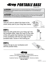
Top Trak Production Stop
The Production Stop measures and records the distance between the end
of the board and the saw blade, drill bit or router cutter. This allows you to
easily cut mul tiple pieces of stock to the exact same length. Cutting numerous
pieces to the exact length without measuring is easy. Gently press the end
of the board opposite the blade against the side of the stop arm as shown at
left. The Production Stop can be secured anywhere along the Top Trak, easily
lifted off the top of the track and reposi tioned on the opposite side of the blade.
The Production Stop features two adjustable lens cursors that can be set
independently to read accurately off of either side of the blade.
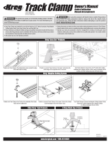
Top Trak
T-Slot
Measuring Tape
Half Dovetail
1/8” Drill
Drill Guide Line
2¼”
¾”
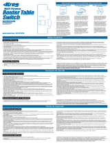
One of the most common
applications for the Precision
Trak & Stop Kit is combined with
a miter saw. The table design,
shown at left allows you to
customize the table height for
your saw. The table box height
should be the same as the height
of the miter saw table. Table
boxes can be placed to the left
or right of the miter saw and will
support the material being cut
as well as provide a mounting
surface for the Top Trak.
The image below shows an expanded view of the end prole of the image
above. The height of the back board should be the height of the table box
PLUS 2-1/4”. The example below shows a table box that is constructed using
pocket hole joinery and pocket hole screws (sold separately). Although this
is an effective method of construction for this application it is not the only
method that may be utilized. The vertical members that are sized for the miter
saw table height are attached to the table box top with pocket hole screws in
15-degree pocket holes. The bottom and the back are attached with pocket
hole screws. If you want to learn more about pocket hole joinery consult your
local Kreg dealer or visit us on the Web at www.kregtool.com.
Top Trak
Knob
Lens
Tape
Work Piece
Stop Arm
1. 2.
At the heart of the Precision Trak & Stop Kit is the Kreg Top Trak. Top Trak
attaches to your ¾” thick fence component such as melamine, plywood, or other
suitable material. A recessed area on top of the track allows you to attach the
Measuring Tape while the T-slot provides a means to guide and anchor the Swing
Stop
™
. The Half Dovetail prole on the front and back of the track anchors the
Production Stop. The fence component must be 3/4” x 2-1/4” for the Top Trak,
Swing Stop™, and Production Stop to function properly. A groove in the rear of
the track functions as a drill guide. Drill a 1/8” screw hole, 1” from each end, then
space the remaining screw holes evenly between the outside holes for a total of
4 or 5 screws per each 2-foot section. To “connect” the 2-foot Top Trak pieces to
form a 4-ft, 6-ft, or 8-ft section simply butt the adjoining pieces and mount in place.
2¼”
Top Trak
Table Box
Kreg Pocket Hole Screws
Kreg Swing Stop
™
Back
Board
Height of the
Miter Saw Table
Miter Saw
Top Trak
Kreg Stops
Back Board
Table Box
Height of the
Miter Saw Table
FT4064
FT4176
FT4063
FT4092
ASSEMBLE THE STOP
Part# Qty. Description
FT4092 1 Stop Arm
FT4063 2 Lens
FT4064 2 10-32 x 1/4” Nylon Screw
FT4176 1 Threaded Knob
*Please see step 4. Measuring Tape for setting the cursor correctly on your stops.
Precision Trak & Stop Instructions

Swing Stop
™
Measuring Tape
Stop
Arm
The Swing Stop™ measures and
records the distance between the end
of the board and the saw blade, drill bit
or router cutter. This allows you to easily
cut multiple pieces of stock to the exact
same length. Cutting numerous pieces
to the exact length without measuring is
easy. Gently press the end of the board
opposite the blade against the side
of the stop arm as shown at left. The
Swing Stop™ can be secured anywhere
along the track. The Swing Stop™ arm
can be assembled on either side of the
Stop Base knob although it must be
positioned between the Stop Base and
the saw blade.
The curved Swing Stop™ arm is
designed to rise automatically when a
board is pushed against the front of the
stop arm as shown at left. The Swing
Stop™ arm rests on top of the work
piece until the board underneath is
removed. When the board is removed
or moved to the side of the Swing Stop
™
the Stop arm drops down and is again
ready to be used as a stop.
About the Lens
Set the Cursor
Locate the Measure Tape
1. Cut a straight 3/4” thick piece of material
exactly 24” long by 3” wide.
2. Turn the board on edge and place the
board with one end against the teeth of the
saw blade as shown at left.
3. Use a square or similar layout tool to
place a pencil mark across the top of the
fence onto the Top Trak on either side of the
indentation for the Self Adhesive Measuring
Tape. Butt the square against the reference
board so that the pencil marks will be
exactly 24” from the blade as shown. If you
have placed Top Trak on both sides of the
blade repeat the same process for the other
side of the blade.
4. Align the 24-3/8” mark of the Self
Adhesive Measuring Tape to the pencil
mark and adhere
the Tape to the indentation along the length
of the Top Trak. Cutoff excess tape with
scissors.
Note: Placing the Tape is much easier if
you slice the backing of the Measuring Tape
under the 24” mark and fold over to expose
only a short amount of the adhesive.
1. Adjust the cursor so it sits about 3/8” from the
edge of the stop. The cursor set screw is on
top of the stop arm.
2. Measure a piece of scrap wood. The exact
length of this scrap is not important. A board
about 24” works well because it gives you
plenty of room to make some test cuts.
3. Set the stop so the cursor reads a length less
than the length of the scrap piece.
4. Cut the scrap board to the new length and
measure the cut board.
5. Without moving the stop loosen the cursor set
screw and adjust it to read this exact
measurement.
Pencil
Marks
Square
24” Pencil
Marks
24”
Board
Red Line
Cursor
3/8” off-set
3/8”
off-set
Saw
Blade
24”
Pencil
Mark
Both the Production Stop and the Swing
Stop™ feature an adjustable lens cursor
similar to the lens on a quality table saw rip
fence.
The lens is a clear material except for a red
line (cursor) on the bottom of the lens as
shown at left. The red line cursor makes it
easy to read the tape lines and ne-tune the
stop when compensating for blade thickness
variations or a tape that is not perfectly
positioned.
Note: When placing the self-adhesive tape
onto the track, the tape must be placed 3/8”
CLOSER TO THE SAW BLADE to allow the
Lens to function properly.
3. 4.
Knob
Stop Base
Lens
Tape
Stop Arm
Top Trak
Workpiece
FT4137
FT4060
FT4261
FT4212
FT4257
FT4262
FT4258
FT4137
FT4061
FT4063
FT4064
FT4257
FT4257
DK1313
ASSEMBLE THE STOP
Part# Qty. Description
FT4261 1 Swing Stop
™
Arm - Position on side of stop base nearest blade
FT4063 1 Lens - Allows precise adjustment of Swing Stop
™
FT4061 1 Nyloc Nut - Won't work loose during use
FT4137 2 Brass Washer - Protects the Plastic Stop Bushing
FT4064 1 Nylon Screw - Used to calibrate lens zero position
DK1313 1 Black T-Knob - Tightens Swing Stop
™
assembly in position
FT4060 1 Hex Head Bolt - Secures Swing Stop
™
assembly
FT4262 1 Stop Base - Anchors assembly to aluminum trak
FT4212 1 T-Bolt - Slides in T-Slot of aluminum trak
FT4257 4 Plastic Stop Bushing - Allows for smooth operation
FT4258 1 Plastic Support Button - Allows for smooth operation
*Please see step 4. Measuring Tape for setting the cursor correctly on your stops.
Precision Trak & Stop Instructions

Four 2 ft. sections of trak lets you set up your shop for the way you work. Additional trak sections and extra stops are available separately.
Congurez votre atelier comme vous le voulez grâce aux quatre sections de rail de 0,61 m. Vous pouvez vous procurer des sections de rail et des butées supplémentaires séparément.
Cuatro secciones de 0,61 m del trak le permitirán congurar su negocio de la manera en que usted trabaja. Las secciones adicionales de trak y los topes adicionales se encuentran disponibles por separado.
Safety Guidlines
Warning
- Woodworking machines are dangerous and can cause personal injury if not used properly.
- Read safety instructions and operating instructions for your machine completely before using products.
Using this system before understanding its safe and proper use could result in serious injury to the operator.
- Warning: Failure to follow these rules may result in serious personal injury.
- For your own safety, read instruction manual before operating the tool. Learn the tools application and
limitations as well as the specic hazards peculiar to it.
- Keep all guards and safety devices in proper place while using these products.
- Always wear safety glasses.
- Keep hands well away from the rotating blade when operating machine.
- Avoid awkward hand positions, where a sudden slip could cause contact with rotating blade. Never reach behind
the rotating blade with either hand to clear the area of debris.
Consignes de sécurité
Avertissement
- Les appareils conçus pour le travail du bois sont dangereux et peuvent causer des blessures s’ils ne sont pas utilisés correctement.
- Lisez toutes les consignes de sécurité et le mode d’emploi de votre appareil avant de l’utiliser.
Vous pourriez subir de graves blessures si vous utilisez ce système sans connaître la méthode correcte et sécuritaire.
- Avertissement : Le non-respect de ces consignes peut causer des blessures graves.
- Pour votre sécurité, lisez le manuel d’instructions avant d’utiliser l’outil. Assurez-vous de connaître le fonctionnement et les restrictions de cet outil ainsi que les
dangers potentiels liés à son utilisation.
- Maintenez tous les protecteurs et les dispositifs de sécurité en place lorsque vous utilisez ces produits.
- Portez toujours des lunettes de sécurité.
- Gardez vos mains loin de la lame lorsque vous utilisez l’appareil.
- Évitez de placer les mains dans une position où elles risquent d’entrer en contact avec la lame en cas de déviation soudaine. Ne mettez jamais la main derrière
la lame pour enlever les débris.
Pautas de seguridad
Advertencia
- Las máquinas para carpintería son peligrosas y pueden provocar lesiones personales si no se usan de manera adecuada.
- Lea completamente las instrucciones de seguridad y de funcionamiento de la máquina antes de utilizar los productos.
El uso de este sistema antes de comprender su utilización segura y adecuada puede causar lesiones graves al operador.
- Advertencia: No seguir estas reglas puede provocar lesiones personales graves.
- Por su propia seguridad, lea el manual de instrucciones antes de operar la herramienta. Conozca las aplicaciones y las limitaciones de la herramienta,
como también sus posibles peligros especícos.
- Mantenga todas las protecciones y los dispositivos de seguridad en el lugar adecuado mientras utiliza estos productos.
- Siempre use gafas de seguridad.
- Mantenga las manos alejadas de la hoja giratoria mientras opere la máquina.
- Evite las posiciones de manos incómodas donde un resbalón repentino podría provocar el contacto con la hoja giratoria. Nunca intente alcanzar la parte
de atrás de la hoja giratoria con las manos para limpiar el área de desechos.
Customize to your shop • Personnalisez votre atelier • Personalice para su negocio
4 foot on either side
1,22 m de chaque côté
1,22 m a cada lado
8 foot, all on one side
2,44 m d’un seul côté
2,44 m, todo de un lado
6 foot and 2 foot
1,83 m et 0,61 m
1,83 m y 0,61 m
WARNING:
!
This product can expose you to chemicals including Acrylonitrile and other chemicals, which are known to the State of California to cause cancer and reproductive harm.
For more information go to www.P65Warnings.ca.gov.
Avertissement :
!
Cet article peut vous exposer à des produits chimiques, notamment à l’acrylonitrile et à d’autres produits chimiques reconnus par l’État de la Californie comme étant la cause de cancers et
de problèmes liés aux fonctions reproductrices. Pour plus de renseignements, rendez-vous au www.P65Warnings.ca.gov.
Advertencia:
!
este producto puede exponerlo a sustancias químicas, incluidas el acrilonitrilo y otros químicos, reconocidas por el estado de California como causantes de cáncer o daños en el aparato
reproductivo. Para obtener más información, visite www.P65Warnings.ca.gov.
/