Page is loading ...

i
Cooling Fresh Air Clean AirHeating
Rittling
Cabinet Convectors
Installation, Operation and Maintenance

Models 1
Ratings 2
Dimensions and data 3
General information 9
Receiving 9
Safety considerations 10
Unpacking and preparation 11
Handling and installation 12
Hot water connections 13
Exposed unit touch-up 14
Heating system 14
Water system balancing 15
Water treatment 15
Maintenance 16
Equipment start-up checklist 16
Replacement parts 17
IMPORTANT: Submittal documentation, specific to
each project, supersedes the general guidelines
contained within this manual.

Models
Floor models
Wall models
FL: Floor, flat top SF: Floor, sloped top
WL: Wall, flat top RL: Wall, semi-recessed
PL: Wall, fully recessedSL: Wall, sloped top
1Models

Steam ratings
Table 1: BTU/H (215 °F at 65 °F E.A.T.)
Depth (in.) Length (in.)
Type SL slope top wall mounted nominal heights Type SF slope top free standing nominal heights
18 20 26 32 18 20 26 32
4
24 3936 4056 4248 4416 3600 3744 4080 4248
28 4776 4896 5112 5304 4320 4488 4896 5112
36 6456 6624 6936 7248 5904 6096 6624 6960
40 7296 7488 7824 8112 6648 6864 7512 7848
48 8952 9192 9600 9984 8136 8448 9192 9624
52 9744 9936 10440 10848 8832 9144 9936 10440
60 11400 11616 12192 12816 10248 10704 11616 12192
64 12288 12528 13128 13920 10992 11544 12528 13176
6
24 6264 6432 6936 7176 5424 5736 6528 6960
28 7560 7752 8328 8688 6528 6888 7752 8328
36 10152 10464 11232 11616 8904 9336 10488 11280
40 11448 11784 12648 13152 9984 10536 11808 12696
48 14064 14448 15528 16104 12336 12888 14496 15576
52 15288 15720 16896 17592 13536 14016 15720 16896
60 17880 18360 19728 20568 15792 16344 18360 19728
64 19224 19752 21216 22080 16848 17640 19776 21312
8
24 7776 8016 8640 9000 7200 7392 8064 8664
28 9408 9648 10416 10824 8640 8880 9648 10416
36 12720 13080 14112 14688 11760 12144 13776 14136
40 14376 14784 15936 16584 13200 13656 14856 16008
48 17664 18096 19560 20376 16320 16776 17760 19656
52 19248 19752 21336 22224 17712 18192 19752 21336
60 22512 23112 24960 26040 20736 21288 23112 24960
64 24216 24888 26832 28008 22392 22992 24960 26928
Table 2: Steam ratings in BTU/H (215 °F at 65 °F E.A.T.)
Depth (in.) Length (in.)
Front outlet nominal heights
18 20 26 32
4
24 2760 3120 3696 3984
28 3312 3816 4464 4776
36 4368 5136 6000 6480
40 4896 5760 6768 7296
48 5952 7080 8304 8952
52 6552 7800 9072 9744
60 7656 9120 10608 11400
64 8136 9744 11376 12264
6
24 4032 4536 5520 6144
28 4848 5520 6672 7368
36 6432 7344 9000 9912
40 7248 8328 10152 11184
48 8880 10200 12432 13656
52 9744 11064 13536 14904
60 11400 13056 15840 17424
64 12192 13992 17016 18744
8
24 5112 5712 6552 7080
28 6384 6960 7896 8520
36 8712 9312 10656 11520
40 9864 10536 12024 12984
48 11952 12960 14736 15984
52 13464 14232 16104 17424
60 15768 16656 18840 20376
64 16776 17784 20256 21936
Ratings above are based on open inlet, derating for inlet louvers is required, see catalog for derating factors
For steam pressures other than 0.9, use correction factors found in catalog
2

Dimensions and data Model PL
Fully recessed wall
Nominal
lengths
(L)
Nominal
heights
(H)
Nominal
depths
(D)
Maximum
dimension
(R)
24"
28"
36"
40"
48"
52"
60"
64"
18"*
20"
26"
32"
4"
6"
8"
3-3/4"
5-3/4"
7-5/8"
Any combination of length, height and depth is available.
3/8" (typical)
8-3/4"
1-3/8"
L
L + 3"
Outlet grille
Inlet opening
Standard element
H + 3"
D
R
H
**
PL Convector Access Door Location Availability
Unit Height Unit Lengths
# of Doors
Available
Available
Locations
Door Size
Less than 18" All Lengths 0 No access door locations available
18" to 19" Less than 32" 1 3, 4, 5, 6 4"H x 5"W
18" to 19" Less than 32" 2 3, 5 or 4, 6 4"H x 5"W
18" to 19" 32" and longer 4 3, 4, 5, 6 4"H x 5"W
20" to 25" Less than 32" 1 1, 2, 3, 4, 5, 6 4"H x 5"W
20" to 25" Less than 32" 2 1, 2 or 3, 5 or 4, 6 4"H x 5"W
20" to 25" 32" and longer 4 3, 4, 5, 6 5"H x 5"W
26" and over Less than 32" 2 1, 2 or 3, 5 or 4, 6 5"H x 5"W
26" and over Less than 32" 4 1, 2, 3, 5 or 1, 2, 4, 6 5"H x 5"W
26" and over 32" and longer 6 1, 2, 3, 4, 5, 6 5"H x 5"W
Standard Convector
Access Door Locations
#3 #4
#1 #2
#5 #6
Note:
Access doors not available in locations 5 and 6 with arched inlet.
*Contact factory on heights less than 20"
For convectors less than 28" long, end pockets are not offered as
standard. Consult factory for availability.
**The coil is adjustable 7/8" up in 7/16" increments.
Optional access
doors shown
3Dimensions and data

Dimensions and data Model RL
Partially recessed wall
Nominal
lengths
(L)
Nominal
heights
(H)
Nominal
depths
(D)
Maximum
dimension
(R)
24"
28"
36"
40"
48"
52"
60"
64"
18"*
20"
26"
32"
4"
6"
8"
3-3/4"
5-3/4"
7-5/8"
Any combination of length, height and depth is available.
Wall
H
D
* 8-3/4''
1-1/2" (typical)
1-3/8''
L + 3''
H + 3''
L
Outlet grille
Inlet opening
Standard element
*
PL Convector Access Door Location Availability
Unit Height Unit Lengths
# of Doors
Available
Available
Locations
Door Size
Less than 18" All Lengths 0 No access door locations available
18" to 19" Less than 32" 1 3, 4, 5, 6 4"H x 5"W
18" to 19" Less than 32" 2 3, 5 or 4, 6 4"H x 5"W
18" to 19" 32" and longer 4 3, 4, 5, 6 4"H x 5"W
20" to 25" Less than 32" 1 1, 2, 3, 4, 5, 6 4"H x 5"W
20" to 25" Less than 32" 2 1, 2 or 3, 5 or 4, 6 4"H x 5"W
20" to 25" 32" and longer 4 3, 4, 5, 6 5"H x 5"W
26" and over Less than 32" 2 1, 2 or 3, 5 or 4, 6 5"H x 5"W
26" and over Less than 32" 4 1, 2, 3, 5 or 1, 2, 4, 6 5"H x 5"W
26" and over 32" and longer 6 1, 2, 3, 4, 5, 6 5"H x 5"W
Standard Convector
Access Door Locations
#3 #4
#1 #2
#5 #6
Note:
Access doors not available in locations 5 and 6 with arched inlet.
*Contact factory on heights less than 20"
For convectors less than 28" long, end pockets are not offered as
standard. Consult factory for availability.
**The coil is adjustable 7/8" up in 7/16" increments.
Optional access
doors shown
4

Dimensions and data Model SL
Wall hung slope top
Nominal
lengths
(L)
Nominal
heights
(H)
Nominal
depths
(D)
24"
28"
36"
40"
48"
52"
60"
64"
18"*
20"
26"
32"
4"
6"
8"
Any combination of length, height and
depth is available.
D + 7/8"
4-3/4"
4" (typical)
1-3/8"
L + 1/8"
Outlet grille
Standard element
H
**
Note:
*Contact factory on heights less than 20"
**The coil is adjustable 7/8" up in 7/16" increments.
For convectors less than 28" long, end pockets are not offered as
standard. Consult factory for availability.
SL Convector Access Door Location Availability
Unit Height Unit Lengths
# of Doors
Available
Available
Locations
Door Size
Up to 20" All lengths 2 1, 2 4"H x 5"W
20" and over All lengths 2 1,2 5"H x 5"W
Standard Convector
Access Door Locations
#3 #4
#1 #2
#5 #6
Optional access
doors shown
5Dimensions and dataDimensions and data

Dimensions and data Model FL
Free standing floor
Nominal
lengths
(L)
Nominal
heights
(H)
Nominal
depths
(D)
24"
28"
36"
40"
48"
52"
60"
64"
18"*
20"
26"
32"
4"
6"
8"
Any combination of length, height and
depth is available.
D + 1/8"
8-3/4"
1-3/8"
L
Outlet grille
Inlet opening
Standard element
H
**
Note:
Access doors not available in locations 5 and 6 with arched inlet.
*Contact factory on heights less than 20"
For convectors less than 28" long, end pockets are not offered as
standard. Consult factory for availability.
**The coil is adjustable 7/8" up in 7/16" increments.
FL Convector Access Door Location Availability
Unit Height Unit Lengths
# of Doors
Available
Available
Locations
Door Size
Up to 18" Less than 32" 1 3, 4, 5, 6 4"H x 5"W
Up to 18" Less than 32" 2 3, 5 or 4, 6 4"H x 5"W
Up to 18" 32" and longer 4 3, 4, 5, 6 4"H x 5"W
19" Less than 32" 1 1, 2, 3, 4, 5, 6 4"H x 5"W
19" Less than 32" 2 1, 2 or 3, 5 or 4, 6 4"H x 5"W
19" 32" and longer 4 1, 2, 5, 6 4"H x 5"W
20" and over Less than 32" 2 1, 2 or 3, 5 or 4, 6 5"H x 5"W
20" and over Less than 32" 4 1, 2, 3, 5 or 1, 2, 4, 6 5"H x 5"W
20" and over 32" and longer 6 1, 2, 3, 4, 5, 6 5"H x 5"W
Standard Convector
Access Door Locations
#3 #4
#1 #2
#5 #6
Optional access
doors shown
6

Dimensions and data Model SF
Free standing slope top
Nominal
lengths
(L)
Nominal
heights
(H)
Nominal
depths
(D)
24"
28"
36"
40"
48"
52"
60"
64"
18"*
20"
26"
32"
4"
6"
8"
Any combination of length, height and
depth is available.
D + 1/8"
8-3/4"
1-3/8"
L + 1/8"
Outlet grille
Inlet opening
Standard element
H
**
Note:
Access doors not available in locations 5 and 6 with arched inlet.
*Contact factory on heights less than 20"
For convectors less than 28" long, end pockets are not offered as
standard. Consult factory for availability.
**The coil is adjustable 7/8" up in 7/16" increments.
SF Convector Access Door Location Availability
Unit Height Unit Lengths
# of Doors
Available
Available
Locations
Door Size
Up to 18" Less than 32" 1 5 or 6 4"H x 5"W
Up to 18" 32" and longer 2 5, 6 4"H x 5"W
18" to 19" Less than 32" 3 1, 2, 5 or 1, 2, 6 4"H x 5"W
18" to 19" 32" and longer 4 1, 2, 5, 6 4"H x 5"W
20" and over Less than 32" 3 1, 2, 5 or 1, 2, 6 5"H x 5"W
20" and over 32" and longer 4 1, 2, 5, 6 5"H x 5"W
Standard Convector
Access Door Locations
#3 #4
#1 #2
#5 #6
Optional access
doors shown
7Dimensions and data

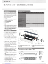
Dimensions and data Model WL
Wall hung
Nominal
lengths
(L)
Nominal
heights
(H)
Nominal
depths
(D)
24"
28"
36"
40"
48"
52"
60"
64"
18"*
20"
26"
32"
4"
6"
8"
Any combination of length, height and
depth is available.
Wall
D + 1/8''
* 4-3/4''
1-3/8''
Outlet grille
L
H
Standard element
Floor
4" min.
*
Note:
Access doors not available in locations 5 and 6 with arched inlet.
*Contact factory on heights less than 20"
For convectors less than 28" long, end pockets are not offered as
standard. Consult factory for availability.
**The coil is adjustable 7/8" up in 7/16" increments.
WL Convector Access Door Location Availability
Unit Height Unit Lengths
# of Doors
Available
Available
Locations
Door Size
Up to 20" Less than 32" 1 3 or 4, 1 or 2 4"H x 5"W
Up to 20" 32" and longer 2 3, 4 or 1,2 4"H x 5"W
20" and over Less than 32" 3 1, 2, 3 or 1, 2, 4 5"H x 5"W
20" and over 32" and longer 4 1, 2, 3, 4 5"H x 5"W
Standard Convector
Access Door Locations
#3 #4
#1 #2
#5 #6
Optional access
doors shown
8

Dimensions and data Model Coil
Note:
Fins are 0.010" thick aluminum.
Header material is cast brass.
*For Convectors with end pockets, subtract end pocket length from length of Convector.
2'' 2'' 2-1/4''
3/4'' THREADED
(FEMALE) N.P.T.
COIL LENGTH
(LENGTH OF CONVECTOR MINUS 1/4'')
COIL CENTERLINE
(LENGTH OF CONVECTOR MINUS 2-3/4'')
COIL WIDTH
WIDTH = (DEPTH - 1/4'')
1/4'' TAPPED VENT PLUG
(BY OTHERS)
1/4'' VENT PLUG
(BY OTHER)
N = Standard Coil
1/4'' VENT PLUG
(BY OTHER)
1/4'' VENT PLUG
(BY OTHER)
B = Optional Coil
*
9

General information
This installation instructions
literature is for Rittling Cabinet
Convectors. Rittling Cabinet
Convectors are hydronic terminal
units designed for high heating
capacity in open or hard-to-
reach areas. Your equipment
is initially protected under the
Zehnder Rittling standard 1-year
warranty provided the steps
outlined in this manual for initial
inspection, installation, periodic
maintenance and normal every
day operation of the equipment
are followed. This manual should
be thoroughly reviewed prior
to the installation, start-up or
maintenance of the equipment.
If any questions arise, please
contact your local Zehnder
Rittling sales representative or
the factory before proceeding
any further.
Upon delivery, examine the
shipment against the bill of
lading to make sure all of the
units have been received and
then check each unit carefully
for shipping damage. Any
damage should be reported to
the freight carrier and a claim
should be filed with them. Ensure
the shipping company makes
proper notation of any shortages
or damage on all copies of the
freight bill. Concealed damage
not discovered during unloading
must be reported to the shipping
company within 15 days of
receipt of the shipment.
All units are shipped F.O.B.
factory. Therefore, Zehnder
Rittling is not responsible for
damage during transit. It is the
responsibility of the installing
contractor to inspect and verify
that the units shipped were in
fact the correct model number,
voltage, etc. Any discrepancies
should be reported to the
local Sales Representative for
immediate resolution prior to
unpackaging and installation.
The factory should be notified
of any warranty repairs required
in writing before any corrective
action is taken. The factory
must be fully informed of the
expected costs before the work
Receiving
is begun. Zehnder Rittling is
not responsible for any repairs
or alterations made by the
purchaser without Zehnder
Rittling’s written consent and
will not accept any back charges
associated with these repairs
or alterations. The return of
damaged equipment will not
be accepted without written
authorization from Zehnder
Rittling.
A unit that has received a written
Return Goods Authorization will
be inspected by Zehnder Rittling
upon receipt. Any damage,
missing parts, reworking or
repackaging resulting from prior
installation will constitute just
cause for Zehnder Rittling to
issue partial credit.
10 General information

Safety considerations
All fastening devices must be
designed to mechanically hold
the assembly in place without
the ability to loosen or break
away due to system operation or
vibration.
Never pressurize equipment
beyond specified pressures.
Always pressure test with an
inert fluid such as water or
dry nitrogen to avoid possible
damage or injury in the event of a
leak or component failure during
testing.
Always protect adjacent
flammable material when welding
or soldering. Use a suitable heat
shield material to contain sparks
or drops of solder. Have a fire
extinguisher readily available.
Please follow standard safe
practices regarding the handling,
installing or servicing of
mechanical equipment.
Read these instructions
thoroughly and follow all
warnings or cautions attached
to the equipment. Consult
local building codes for special
installation requirements.
Understand the signal words:
danger, warning and caution.
Identifies the most serious
hazards which will result in
severe personal injury or death.
Signifies hazards that could
result in personal injury or death.
Used to identify unsafe
practices, which would result in
minor personal injury or product
and property damage.
The installation of Rittling
Cabinet Convectors and all
associated components, parts
and accessories which make
up the installation, shall be in
accordance with the regulations
of all authorities having
jurisdiction and must conform to
all applicable codes. Only trained
and qualified service personnel
using good judgment and safe
practices should install, repair
and/or service air conditioning
equipment.
Untrained personnel can perform
basic maintenance functions
such as cleaning coils. All other
operations should be performed
by trained service personnel.
When working on air conditioning
equipment, observe precautions
in the literature, tags and labels
attached to the equipment and
all other safety precautions that
may apply.
Improper installation,
adjustment, alteration, service,
maintenance, or use can cause
hazardous conditions which
may cause serious personal
injury and/or property damage.
Consult a qualified installer,
service agency, or your sales
representative for information or
assistance.
The equipment must always be
properly supported by rigging and
lifting equipment. Any temporary
supports used during installation
or maintenance must be designed
to adequately hold the equipment
in place until equipment is
permanently fastened and set
in its final location. All supports
must meet applicable local codes
and
ordinances.
The manufacturer assumes
no responsibility for personal
injury or property damage
resulting from improper or unsafe
practices during the handling,
installation, service or operation
of the equipment. The installation
of cabinet convectors and all
associated components, parts
and accessories shall be in
accordance with the regulations
of all authorities having
jurisdiction and must conform
to all applicable codes. It is the
responsibility of the installing
contractor to determine and
comply with all applicable codes
and regulations.
11

Unpacking and
preparation
All units are carefully inspected
at the factory throughout the
entire fabrication and assembly
processes under Zehnder
Rittling’s stringent quality
assurance program.
Each unit is carefully packaged
in a cardboard container and
filled with kraft paper padding
for shipment to avoid damage
during normal handling in the
shipment process. It is the sole
responsibility of the customer
to provide the protection
necessary to prevent vandalism
and weather deterioration
of the equipment. Under no
condition should the units be left
unprotected from the elements.
If the equipment is not needed
immediately at the job site, it
should be left in its shipping
carton and stored in a clean,
dry area of the building or in a
warehouse. Do not remove any
equipment from its shipping
package until it is needed for
installation. The equipment
is NOT suitable for outdoor
installations.
After determining the condition of
the cardboard container exterior,
carefully remove each unit from
the container and inspect for
hidden damage. At this time,
check that all shipped loose
items are accounted for and
placed in a safe area. Any hidden
damage should be recorded
and immediately reported to
the carrier and a claim should
be filed. In the event a claim for
shipping damage is filed, the
unit, cardboard container, and all
packing must be kept for physical
inspection by the freight carrier.
Once the equipment is properly
positioned on the job site,
cover the units with either a
shipping carton, vinyl film, or an
equivalent protective covering.
Cap open ends of piping that is
stored on a job site. Take special
care to prevent foreign materials
from entering the units in areas
where painting, dry walling, or
spraying of fireproof material,
etc. has not yet been completed
as these materials may
accumulate on the coil. Foreign
material that accumulates
within the units can prevent
proper start-up, necessitate
costly clean-up operations,
or result in immediate or
premature component failure.
Before installing any of the
system components, be sure to
examine each pipe, fitting and
valve, and remove any dirt or
foreign material found in or on
these components. Some job
conditions may require some
form of temporary unit covering
during construction.
DO NOT store or install units
in corrosive environments or in
locations subject to temperature
or humidity extremes (e.g.,
attics, garages, rooftops, etc.).
Corrosive conditions and high
temperature or humidity can
significantly reduce system
performance, reliability and
overall service life.
12 Unpacking and preparation

Handling and
installation
While all equipment is designed
for durability and fabricated with
heavy gauge materials and may
present a robust appearance,
great care must be taken to
assure that no undue force
is applied to the coil, piping
or other components during
handling. Gloves should be
worn when handling finished,
painted units and should never
be set down on unclean, hard
surfaces. Failure to follow
these instructions may lead to
scratching or gouging of the
finished surface.
Although Zehnder Rittling
does not become involved
with the design and selection
of support methods and/
or components, it should be
recognized that unacceptable
operating characteristics and/
or performance may result from
poorly implemented unit support.
Additionally, proper clearance
must be provided for service and
removal of the equipment.
Make sure that the convector
liners are secured tight to
the mounting surface. Using
fasteners, supplied by others,
attach the liner to wall studs by
penetrating the liner wherever
necessary. Locate the convector
coil in the coil clips located on
each end of liner, making sure to
provide proper pitch down from
the supply end if the convector is
being used in a two pipe steam
system.
Upon installation, make sure that
all sweated connections have
been flushed with system water
to avoid corrosion from left over
flux material.
Once the coil is connected into
the heating system, a standard
pressure leak test should be
conducted as specified by the
engineer.
After completion of the pressure
leak test, install the convector
front onto the convector liner.
Make sure that latching screws
for access doors (if any) are
secured with the door closed. If
the convector is supplied with an
optional damper, open and close
the damper blade, with the knob
damper provided, to make sure
that there is no binding of the
blade during operation.
After mounting the unit, it is
then ready for the water or
steam service connection. At
this time it should be verified
that the proper type of service is
actually provided to the unit. On
those units requiring hot water,
the proper line size and water
temperature should be available
to the unit.
On units with steam heating
coils, the proper line sizing and
routing should be verified. The
maximum steam pressure should
never exceed 50 psig. The drain
piping and steam trap, supplied
by others, should be sized
and routed to allow for proper
condensate flow.
13

Hot water connections
14
Hot water
connections
All coil connections are to be
made with a threaded joint.
Use specified pipe dope or
thread sealer tape for threaded
connections to the cast bronze
headers. Make sure that the pipe
fitting going into the header is
not over tightened. This may
cause the header to split.
After the connections are
completed, the system should
be tested for leaks. Since
some components are not
designed to hold pressure with
a gas, hydronic systems should
be tested with water. Test
pressure must not exceed 250
psig. Pressure testing should
be completed prior to sheet
rocking, finished floors, painting,
caulking, etc.
All water coils must be protected
from freezing after initial filling
with water. Even if the system is
drained, unit coils may still hold
enough water to cause damage
when exposed to temperatures
below freezing.
In the event that leaking or
defective components are
discovered, the Zehnder Rittling
Sales Representative must be
notified before any repairs are
attempted. All leaks should be
repaired before proceeding with
the installation.
After system integrity has been
established, the piping should
be insulated in accordance with
the project specifications. This is
the responsibility of the installing
or the insulation contractor.
Zehnder Rittling will not accept
any charges associated with
re-insulating piping if the
installing contractor failed to
establish system integrity prior to
insulating.

15
Units will be furnished with an
epoxy powder coated paint finish.
Small scratches in the finish may
be repaired with touch-up spray
paint available from the factory.
Proper safety procedures should
be followed regarding ventilation
and personal safety equipment
when using spray paint. Follow
the manufacturer’s directions for
the products being used.
To repaint the factory powder
coat finish, prepare the surface
by lightly sanding with #280 grit
sand paper or #000 or #0000 fine
steel wool. The surface may also
be wiped with a liquid surface
etch cleaning product. These
items should be available at most
paint product stores. It should be
noted that the more care taken
during this process, the more
effective it will be.
Exposed unit touch-up
and repainting
Heating system
After this preparation is finished,
the factory finish should provide
excellent adhesion for a variety
of air dried top coats. Enamel will
give a more durable, higher gloss
finish, while latex will not adhere
as well and will give a dull, softer
finish. Top coats involving an
exothermic chemical process
between two components such
as epoxies and urethanes should
be avoided.
All standard colors including
primer can be painted over. If the
installing contractor chooses not
to paint over the primer color,
the factory cannot match primer
color on future orders, potentially
causing color match issues in the
field.
Factory touch-up spray paint
may require a number of light
coats to isolate the factory finish
from the quick drying touch-up
paint.
Prior to the water system
start-up and balancing, the
hot water system should be
thoroughly flushed to clean
out dirt and debris which may
have accumulated in the piping
during construction. During this
procedure, all unit service valves
must be in the closed position.
This will prevent any foreign
material from entering the unit’s
heat exchanger and clogging
valves and metering devices.
Strainers should be installed in
the piping mains to prevent this
material from entering the units
during normal operation.
During system filling, air venting
should be done through air vents
provided in the main system.
Inspect the entire system
for potential air traps and
independently vent those areas
as required. In addition, some
systems may require repeated
venting over time to fully
eliminate air in the system.

16
Water system
balancing
A complete knowledge of the
hydronic system, including its
components and controls, is
essential to proper water system
balancing and should only be
completed by a qualified expert. The
system must be complete, and all
components must be in operating
condition before beginning the water
system balancing procedures.
Each hydronic system has different
operating conditions depending on
the devices and controls installed for
the particular application. The actual
balancing technique may vary from
one system to another.
After the proper system operation
is established, the appropriate
operating conditions such as
water temperatures, flow rates and
pressure drops should be recorded
for future reference.
Before and during water system
balancing, conditions may exist due
to incorrect system pressures which
may result in noticeable water noise
or undesired valve operation. After
the entire system is balanced, these
conditions will not exist on properly
designed systems. If any of these
conditions persist, recheck the
system for air that may not have been
properly vented during start-up.
Water treatment
Proper water treatment is
a specialized industry and
therefore it is recommended
to consult an expert in this
field to analyze the water for
compliance with the water
quality parameters listed below
and to specify the appropriate
water treatment program. The
expert may recommend rust
inhibitors, scaling preventative,
antimicrobial growth agents or
algae preventatives. Anti-freeze
solutions, glycols, may also be
used to lower the freezing point.
Water content Required concentration
Sulphate < 200 ppm
pH 7.0 – 8.5
Chlorides < 200 ppm
Nitrate < 100 ppm
Iron < 4.5 mg/L
Ammonia < 2.0 mg/L
Manganese < 0.1 mg/L
Dissolved solids < 1000 mg/L
Calcium carbonate hardness 300 – 500 ppm
Calcium carbonate alkalinity 300 – 500 ppm
Particulate quantity < 10 ppm
Particulate size 800 micron max
All Zehnder Rittling water coils
are constructed of copper tubes
and brass headers. It is the end
user’s responsibility to ensure
that any of the water delivery
components are compatible with
the treated water.
Failure to provide proper water
quality will void the fan coil unit’s
warranty.
Water system balancing and treatment

17
Before each heating season,
remove front panel and inspect
coil fins for accumulation of dust
or other debris that may block
airflow between fins. Brush the
entire finned surface with a soft
bristled brush, brushing parallel
to the fins, taking care not to
damage the fins. Brushing should
be followed by cleaning with a
vacuum cleaner. Compressed
air can also be used by blowing
air through the coil fins, again
followed by vacuuming. If fins
are damaged during the cleaning
process, use an instrument
screwdriver or other small, flat-
edged tool to restraighten fins.
Maintenance
For a deeper cleaning, spray
the finned surface with a mild
alkali cleaning solution and rinse
thoroughly.
Failure to maintain a clean coil
surface will result in reduced
performance.
Inspect for leaks. Replace front
cover. If a damper is included,
ensure that the damper is able to
move freely.
Equipment start-up
checklist
Heating connections
Connect field piping to unit
Pressure test all piping for
leaks
Install drain lines and traps, as
required
Insulate all piping, as required
Unit start-up
General visual inspection and
system inspection
Close all unit isolation valves
Flush water systems
After system has been flushed,
ensure all isolation valves are
open
Receiving and inspection
Unit received undamaged
Unit received complete as
ordered
Unit structural support is
complete and correct
Handling and installation
Unit mounted level and square
Proper access is provided for
unit and accessories
Proper hot water line size to
unit
Unit protected from dirt and
foreign matter

18
Replacement parts
Factory replacement parts
should be used wherever
possible to maintain unit
performance and its normal
operating characteristics.
Replacement parts may
be purchased through the
local Zehnder Rittling Sales
Representative.
Contact the local Sales
Representative or factory
before attempting any unit
modifications. Any modifications
not authorized by the factory
could result in personnel injury,
damage to the unit, and will void
the manufacturer’s warranty.
When ordering parts, the
following information should be
supplied to ensure proper part
identification:
Complete unit model number
Complete part description
including any identifying
numbers on the part
On warranty replacements, it
is often necessary to return the
faulty component to receive
credit. Contact the local Sales
Representative who will get
authorization from the factory
including an RGA (Returned
Goods Authorization) to be used
when sending components back
for inspection. Any returned
components sent back to the
factory without the proper
RGA attached will cancel any
outstanding credit.
Replacement parts
/