Page is loading ...

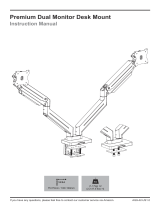
ASSEMBLY AND ADJUSTMENT
EDGE2 Model EDGE2-SLV
Model EDGE2-BLK
Model EDGE2-WHT
DUAL MONITOR ARM
EDGE2 Rev A 2/17

2
PLEASE REVIEW these instructions before beginning the assembly and adjustment procedures. Check that
all the parts and tools listed below were provided with your order. Contact your supplier if any materials are
your satisfaction.
EDGE2 DUAL MONITOR ARM PARTS AND TOOLS
Base Assembly (1) Monitor Arm Assembly (2)
Clamp Pad (1) Grommet Mount Plate (1) Grommet Bar (1) Grommet Bolt (1)
Grommet Bolt Washer (1)
M10x27
Grommet Bolt Nut (2) 14mm Wrench (1)
2mm Allen Key (1) 4mm Allen Key (1) 5mm Allen Key (1)
M4x9M4x10M4x10
VESA Plate Screw (8) VESA Locking Screw (2) 180° Locking Screw (2)
PARTS AND TOOLS PROVIDED
CAUTION: Hand-tighten
screws only. Do not use
power tools.
ADDITIONAL TOOLS REQUIRED
• Phillips screwdriver
3x 3
/8-16
9
/16 x3/8-16

3
Peel and
Adhere
Clamp Method
The base assembly is shipped with the bottom clamp in the “upper attachment position.” To change to the
“lower attachment position” for thicker work surface, follow this procedure (see illustrations):
• Use the 4mm Allen key to remove the two screws holding the bottom clamp in position.
• Reattach the bottom clamp to the lower two holes. Tighten the screws securely using the Allen wrench.
CAUTION: Do not use a power drill. Clamp screws are rated at 102 in-lbs.
Attach Clamp Pad
• Peel the backing from the adhesive side of the clamp pad and adhere the pad
to the bottom of the base, as shown. The pad protects the work surface.
Install Base Assembly
• Clamp the base assembly to the work surface. Be sure to tighten the knob
securely.
• Proceed to “Install Monitor Arm Assemblies” on page 5.
Two Base Assembly Attachment Methods
• Clamp method. The base assembly is clamped to
a table or desk surface that is between 0.6" (15mm)
thick and 3" (76mm) thick. See below.
• Grommet method. The base assembly is secured
through a grommet hole in the work surface, with
a diameter between 0.78" (20mm) and 2" (51mm).
Surface thickness must be between 0.6" (15mm)
and 1.5" (38.1mm). See page 4.
INSTALLATION OF BASE ASSEMBLY EDGE2 DUAL MONITOR ARM
Bottom
Clamp
Assembly
Upper Attachment
Position (Standard)
Lower Attachment
Position (Optional)
To Change: 1) Remove
Upper Attachment Screws
2) Re-Install Screws with
Clamp in Lower Position
Bottom
Clamp
Assembly
Remove
Re-Install
Upper
Attachment Lower
Attachment
1.38" – 3"
(35mm – 76mm)
0.6" – 2.2"
(15mm – 56mm)
Grommet
Method
Clamp
Method
Grommet
Method
Clamp
Method

4
Grommet Method
This method can be used for work surfaces that have a grommet hole in an
appropriate position. Surface thickness must be between 0.6" (15mm) and
1.5" (38.1mm), and the grommet hole diameter must be between 0.78" (20mm)
and 2" (51mm).
Remove Clamp Assembly
• Remove the standard clamp assembly from the
base assembly. Use the 4mm Allen key to remove
the three screws holding the clamp assembly in
position. Retain the three screws.
Attach Grommet Assembly
• Place the grommet bolt in the large center hole on
the grommet mount plate.
• With the grommet bolt in position, fasten the
grommet mount plate and bolt to the monitor arm
base with the three screws previously removed. As
before, use the 4mm Allen key.
Attach Clamp Pad
• Peel the backing from the adhesive side of the clamp pad and adhere the
pad to the bottom of the grommet mount plate, as shown. The pad protects
the work surface.
Install Base Assembly
• Place the base assembly over the grommet hole, with the bolt centered.
• The bolt must extend under the work surface a minimum of 1.3" (33mm).
• Secure the base assembly as illustrated.
— Secure the grommet bar and washer with one of the grommet bolt nuts.
Use the provided wrench to tighten the nut securely.
—
assembly.
• Proceed to “Install Monitor Arm Assemblies” on page 5.
0.6" – 1.5"
(15mm – 38.1mm)
Remove
Clamp
Assembly
Attach
Grommet
Assembly
Peel and
Adhere
Base
Assembly
Grommet
Bar
Washer
Nuts Wrench
EDGE2 DUAL MONITOR ARM INSTALLATION OF BASE ASSEMBLY

5
Install Monitor Arm Assemblies
• Insert the monitor arms into the base assembly.
• Secure each monitor arm by tightening the set screws
using the 2mm Allen key. Adjust the tightness to allow
for the desired ease of monitor arm rotation.
Install Monitors
• Remove the VESA plate from each VESA mount by pressing
down on the plastic tab to release the lock. Pull the plate
upward to remove.
• Place each of the LCD monitors face down on a at
surface. Align the VESA plate holes with the holes
on the back of the monitor. Attach the VESA plates
using the eight VESA plate screws provided (four
screws per monitor).
— There are two sets of four holes on each VESA
plate. One set has holes 3.9" (100mm) apart, the
other set has holes 3" (75mm) apart. Use the set
that matches the holes on the monitor.
MONITOR INSTALLATION EDGE2 DUAL MONITOR ARM
Tighten
Set Screw
VESA
Plate 1.
2.
VESA
Plate
Screw VESA Plate
3.9"
(100mm)
3"
(75mm)
Monitor
(Face Down)
Upward

6
• Slide each VESA plate (with monitor attached) back onto the VESA mount. Make sure the VESA plate
clicks securely in place.
— Optional: Install a VESA locking screw behind each VESA plate to prevent the tab on the VESA plate
from releasing the monitors. Tilt the monitor down for easier access to the screw hole.
Cable Management
Use the cable clip and cable cover to help manage
the monitor cables.
• Pinch the cable clip to remove it from the motion
arm, and again when re-installing it with the cables
captured.
• Slide the cable cover out from the xed arm. Slide it
back in with the cables captured.
180° Lock-Out Feature
• Use the 2mm Allen key to secure the 180° locking
screws into the base of each monitor arm assembly
to limit the xed monitor arm rotation to 180°. Fully
tighten the screws, then back out one full turn.
EDGE2 DUAL MONITOR ARM MONITOR INSTALLATION
VESA
Locking
Screw
(Optional)
Motion
Arm
Cable Cover
Cable
Clip
Fixed
Arm
180° Locking
Screws

7
Tension Adjustments
1. Monitor swivel adjustment
— Use the 2mm Allen key to adjust the set screw for the desired ease of monitor rotation.
2. Motion arm swivel adjustment
— Use the 2mm Allen key to adjust the set screw for the desired ease of motion arm rotation.
3. Fixed arm swivel adjustment
— Use the 2mm Allen key
4. Monitor tilt adjustment
— Use the 4mm Allen key to adjust the set screw for the appropriate monitor weight.
5. Monitor arm weight adjustment
— Use the 5mm Allen key to adjust the set screw for the appropriate monitor weight.
— Weight capacity per arm is 6.5 lbs to 17.6 lbs (2.9 kg to 7.98 kg). Capacity may be reduced if monitor
size is greater than 26" (66cm) or depth is greater than 2.17" (55mm).
FINAL ADJUSTMENTS EDGE2 DUAL MONITOR ARM
Store
Allen Keys
for Future
Adjustments
Allen Key Storage
• Insert the Allen keys into the holes behind the VESA plate to store for future
adjustment.
— Insert the two smaller Allen keys into the same hole.
Tension
Adjustments
Behind
VESA
Plate
1
2
3
5
4

800.833.3746 esiergo.com
© 2017 ESI Ergonomic Solutions. All rights reserved. EDGE2 Rev A 2/17
/