Page is loading ...

1
Kit Contents
Boiler MBH 50 MBH 75MBH 75 MBH 100 MBH S3 100 MBH S2
Fuel NAT/LP NAT LP NAT/LP NAT/LP
Kit Number 550002825 550002826 550002828 550002827 550002829
Control Panel Assembly X X X X X
Burner Plate X X X X X
Hot Surface Igniter X X X X X
Upgrade Label X X X X X
Inducer X
Air Baffl e X
050/075/100 FIELD CONVERSION INSTRUCTIONS
DSI TO HSI
Kit #'s 550002825, 550002826, 550002827, 550002828, 550002829
WARNING
Fire, explosion, asphyxiation and electrical shock
hazard. Improper installation could result in
death or serious injury. Read this instruction
and understand all requirements, including
requirements of authority having jurisdiction,
before beginning installation. Installation not
complete until appliance operation verifi ed per
Installation, Operation & Maintenance Manual
provided with boiler.
!
Kit installation shall be completed by qualifi ed agency.
Tools needed for Kit applications:
1.
Screw Drivers - Phillips and Flat
2.
Wire Cutters
3.
Pliers
4.
Nut Drivers 5/16 & 7/16
5.
Drill Bit Set
6.
1" Hole Saw or Step Drill
7.
Marker
8.
Adjustable Wrench
9.
Combustion Analyzer
NOTICE
Draining boiler is not necessary for this process.
Keep this manual near boiler
Retain for future reference
Replacement Installation, Operation
and Maintenance Manual included with
Kit Instructions.

P/N 240010144, Rev. A [05/2013]
DSI Removal:
1.
Follow instructions to TURN OFF GAS TO
APPLIANCE found on Operating Instructions
label on boiler or in Installation, Operation &
Maintenance Manual. Verify all electrical power to
boiler is turned off.
WARNING
Electric shock hazard. Turn OFF electrical power
supply at service panel.
2.
Remove front and top jacket panel(s).
WARNING
Burn hazard. Verify heat exchanger has cooled or
use appropriate personal protection equipment.
!
3.
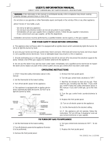
Inspect combustion chamber through sight glass.
Verify fl ame is not present. See fi gure 1.
4.
Disconnect wires at:
A. Casting temperature switch. See fi gure 1.
B. Gas Valve
C. Igniter ground and ground wire
D. Inducer Temperature Switch. See fi gure 2.
Kit installation shall be completed by qualifi ed agency.
WARNING
Fire, explosion, asphyxiation and electrical shock
hazard. Improper installation could result in
death or serious injury. Read these instructions
and understand all requirements, including
requirements of authority having jurisdiction,
before beginning installation. Installation is not
complete until appliance operation is verifi ed per
Installation, Operation & Maintenance Manual
provided with boiler.
!
Figure 1 - Sight Glass, Casting Temperature
Switch,Gas Valve Igniter
Figure 2 - Inducer Temperature Switch
Sight Glass
A
B
C
D
DSI Removal

3
5.
Remove temperature sensor from thermo well,
save clip. See fi gure 3.
6.
Locate wire bundle going to external junction box.
Cut the wire bundle. See fi gure 4.
7.
Disconnect pressure hoses at: See fi gure 5.
A. Gas valve - reference port
B. site glass
C. intake
DSI Removal Conti.
Figure 3 - Temperature Sensor, Clip and Well
Figure 4 - Wire Bundle to External Junction Box
Figure 5 - Pressure Hoses

4
Figure 6 - Remove Existing Control Panel Asembly
Figure 7 - Remove Existing Igniter
8.
Lift, twist and remove control panel assembly. See
fi gure 6.
9.
Remove existing igniter. See fi gure 7.
10.
Disconnect air intake at Fernco connection.
Remove nuts holding mixing valve to casting. See
fi gure 8.
Figure 8 - Fernco Connection
DSI Removal Conti.

5
DSI Removal Conti.
11.
Remove mixing valve body and fi rst gasket. See
fi gure 9.
12.
Remove existing burner plate.
13.
Disconnect all wires connected inside the junction
box.
14.
Remove small conduit knockout from upper left of
junction box. See fi gure 10.
15.
Mark hole from knockout on panel for location.
See fi gure 10.
16.
Remove two screws holding junction box. Remove
junction box. Save screws and junction box for
use.
17.
Drill out 1 inch hole in center of hole marked from
knockout, deburr. Predrill to avoid scratching
sheet metal. See fi gure 12.
18.
Remove strain relief attached to junction box.
Dispose of cut wires and strain relief. See fi gure
11.
Figure 12 - Drill Hole For Junction Box
Figure 10 - Mark Knockout Hole on Sheet Metal
Figure 11 - Remove Wire Strain Relief
Figure 9 - Mixer with Gasket
Note: Additional hole
is required for low
voltage wires.

6
Figure 13 - Install Replacement Junction Box
Figure 14 - Install Supplied Replacement Control
Panel Assembly
19.
Kit 550002829 (100 MBH ONLY) :
A. Remove inducer assembly , 4 screws. See
fi gure 2.
B. Remove air baffl e plate inside fernco fi tting. See
fi gure 8.
HSI Installation:
1.
Attach junction box to side of boiler panel with two
screws. See fi gure 13.
2.
Install replacement control panel assembly. See
fi gure 14.
3.
Install supplied burner plate and gasket.
4.
Attach burner ground spade to outside stub. Verify
ground spade is between burner orifi ce plate and
gasket. See fi gure 15.
Figure 15 - Mixer Ground and Gasket
DSI Removal Conti.

Figure 17 Install Hot Surface Igniter
Figure 18 Connect to Casting Temperature Switch, Inducer, Gas Valve, Igniter Ground and Ground Wire
HSI Installation
Figure 16 Attach Gasket and Gas Mixing Valve
5.
Attach gas valve body. Leave nuts loose. See
fi gure 16
6.
Install supplied hot surface igniter with two
screws. Tighten all screws holding gas mixer in
place. Ensure wire crimp of grounding spade is
under the gasket. See fi gure 17.
7.
Kit 550002829 (100 MBH only) :
• Install supplied inducer with 4 pin connector.
• Install supplied air baffl e plate marked "100
S3" inside Fernco fi tting. See fi gure 8.
8.
Connect wires at: See fi gure 18.
A. Casting temperature switch
B. Inducer temperature switch
C. Gas Valve
D. Igniter ground and ground wire

8
Figure 19 Connect Thermostat and Power Wires
Figure 20 Insert Sensor and Install Sensor Clip
HSI Installation
9.
Run wire bundle with power wires to center of
knock out of junction box. Snap black strain relief
in place. See fi gure 19.
10.
Run thermostat control wires to upper left knock
out. Snap grey strain relief in place. See fi gure 19.
11.
Insert supplied temperature sensor into thermo
well. Ensure it is inserted in all the way. The
temperature sensor serves as the LWCO and must
have contact with the sidewall of the well for
operation. See fi gure 20.

9
HSI Installation
Figure 21 Pressure Tube Routing
12.
Connect pressure tubes: See fi gure 21.
A. Site glass - run tube over gas valve assembly
and/or piping creating an inverted u-trap.
Translucent silicone tubing coming from a tee.
B. Gas valve - reference port. Clear silicone tube
coming from a cross.
C. Air intake. Clear silicone tube coming from the
cross.
13.
Wire junction box internal wires and cover plate.
See fi gure 19.

10
Natural Gas LP
MBH CO
2
CO MBH CO
2
CO
50 8.7- 9.7 < 100 50 10.0 - 11.1 < 100
75 8.7- 9.7 < 100 75 10.0 - 11.1 < 100
100 8.7- 9.7 < 100 100 10.0 - 11.1 < 100
Table 1 - Manufacturer Settings
14.
Install top boiler panel.
15.
Turn on electric and gas to boiler
16.
Resume operation using OPERATING
INSTRUCTIONS found on Operating Instructions
label on boiler or in Installation, Operation &
Maintenance Manual.
17.
Verify proper operation by following START
UP PROCEDURE in Installation, Operation &
Maintenance Manual.
18.
Verify Combustion:
A. Adjust gas pressure for optimal A/F ratio.
Gas pressure and fl ow will be lower after kit
installation. Refer to table 1 for combustion
settings.
B. Install adjustment screw and cover. Verify
settings.
C. Operate boiler thru several cycles after setting
the gas pressure to verify ignition quality.
19.
Attach upgrade label next to rating plate. See
fi gure 23.
20.
Install front jacket panel(s).
Figure 23 - Label Placement
HSI Installation

11
NO
TE
S
Prior to leaving job site review supplied instructions for :
1.
Proper Venting Material
2.
Proper Venting Size
3.
Proper Venting Installation
4.
Review Control Setup and Operation
Questions: Contact Technical Support - 800-241-5501
IMPORTANT

12
Company Address & Phone #Company Name & Tech InitialsService PerformedDate
SERVICE RECORD

2
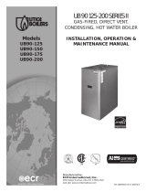
DIMENSIONS
2
Figure 1 - Boiler Dimensions
NOTICE
Draft inducer (blower) may be
rotated 90° or 180° to orient
vent connection towards right
side or rear.

3
INTRODUCTION
Introduction
• This appliance is a gas-fi red direct vent hot water boiler
with cast aluminum boiler sections.
• The heating system water absorbs large amounts of
heat from the cast aluminum heat exchanger, cooling
fl ue gases and causing condensation.
• Sealed combustion, premix gas burner, and low fl ame
temperature means reduced CO and NOx emissions,
which contribute to cleaner and healthier environment.
• This appliance takes its combustion air directly from
outdoors (sealed combustion) and does not compete
with building occupants for fresh air.
• Sealed combustion (also known as “direct vent”)
is safest and best way to obtain plenty of clean
combustion air.
Dimensions ....................................................................................................................2
Introduction ................................................................................................................... 3
Important Safety Information ........................................................................................... 4
Boiler Ratings & Capacities ..............................................................................................5
Boilers For Use At High Altitude - United States Installations ................................................ 6
Before Installing The Boiler ..............................................................................................8
Boiler Installation ...........................................................................................................9
Near Boiler Piping ......................................................................................................... 11
Combustion Air And Vent Pipe ........................................................................................ 22
Gas Supply Piping ......................................................................................................... 28
Electrical Wiring ........................................................................................................... 30
Controls And Accessories ............................................................................................... 34
Start Up ...................................................................................................................... 36
Operating Instructions ................................................................................................... 37
Detailed Sequence Of Operation ..................................................................................... 38
Verifi cation Procedure And Adjustment ............................................................................ 42
Differential Air Pressure Switch Check - All Models ............................................................ 45
Negative Pressure Switch Check ..................................................................................... 46
Maintenance And Cleaning ............................................................................................. 47
Troubleshooting ............................................................................................................ 49
Troubleshooting - High Limit Control And LWCO ............................................................... 50
Troubleshooting -Hydrostat High Limit Control And LWCO .................................................. 51
Appendix A - Water Quality, Water Treatment And Freeze Protection ........................58
Installation And Check-Out Certifi cate ............................................................................. 62
• Induced draft fan draws in outside combustion
air, takes cooler fl ue gases from boiler unit and
provides positive removal of fl ue gases from the
building through readily available PVC, CPVC and PP
(Polypropylene) pipes.
• These low pressure gas-fi red hot water boilers are
design certifi ed by CSA International for use with
natural gas and propane gas.
• Boilers are constructed and hydrostatically tested for
maximum working pressure of 50 psig (pounds per
square inch gage) in accordance with A.S.M.E. Boiler
and Pressure Vessel Code Section IV Standards for
heating boilers.

4
Installation shall conform to requirements of
authority having jurisdiction or in absence of such
requirements:
•
United States
• National Fuel Gas Code, ANSI Z223.1/NFPA 54
.
• National Electrical Code, NFPA 70.
• Canada
• Natural Gas and Propane Installation Code, CAN/CSA
B149.1.
• Canadian Electrical Code, Part I, Safety Standard for
Electrical Installations, CSA C22.1
Where required by authority having jurisdiction,
installation shall conform to Standard for Controls
and Safety Devices for Automatically Fired Boilers,
ANSI/ASME CSD-1.
Additional manual reset low water cutoff and/or manual
reset high limit may be required.
Requirements for Commonwealth of
Massachusetts:
Boiler installation must conform to Commonwealth of
Massachusetts code 248 CMR which includes but is not
limited to:
• Installation by licensed plumber or gas fi tter.
Installers - Follow local regulations with respect to
installation of CO (Carbon Monoxide) Detectors. Follow
maintenance recommendations “Maintenance And Cleaning”
on page 47 .
NOTICE
Used to address practices not related to personal
injury.
CAUTION
Indicates a hazardous situation which, if not avoided,
could result in minor or moderate injury.
!
!
WARNING
Indicates a hazardous situation which, if not avoided,
could result in death or serious injury.
!
DANGER
Indicates a hazardous situation which, if not avoided,
WILL result in death or serious injury
!
This is the safety alert symbol. Symbol alerts you to
This is the safety alert symbol. Symbol alerts you to
potential personal injury hazards. Obey all safety messages
potential personal injury hazards. Obey all safety messages
following this symbol to avoid possible injury or death.
following this symbol to avoid possible injury or death.
Become familiar with symbols identifying
Become familiar with symbols identifying
potential hazards.
potential hazards.
General
Boiler installation shall be completed by qualifi ed agency.
See glossary for additional information.
WARNING
Fire, explosion, asphyxiation and electrical shock
hazard. Improper installation could result in death
or serious injury. Read this manual and understand
all requirements before beginning installation.
!
IMPORTANT SAFETY INFORMATION
Keep this manual near boiler
Retain for future reference

5
Table 1 - SEA LEVEL RATINGS – NATURAL AND PROPANE GASES
Model
Input
*(MBH)
++ Heating Capacity
*(MBH)
Net AHRI Rating
*(MBH)
Shipping
Weight (lbs.)
AFUE
90-50 50 45 39 220
90.0
90-75 75 68 59 220
90.0
90-100 100 90 78 220
90.0
* 1 MBH = 1,000 Btuh Btuh = British Thermal Units Per Hour
BOILER RATINGS & CAPACITIES
++ AFUE (Annual Fuel Utilization Effi ciency) and Heating Capacity is based on the D.O.E. (Department of Energy) test
procedure.
Heating Capacity indicates the amount of heat available after subtracting losses up the stack. Most of this heat is available
to heat water. A small portion is heat from jacket and surfaces of the boiler, and it is assumed that this heat stays in the
structure.
Net AHRI rating represents portion of remaining heat that can be applied to heat radiation or terminal units (i.e. fi nned
tube baseboard, cast iron radiators, radiant fl oor, etc.). The difference between Heating Capacity and Net AHRI Rating,
called piping and pickup allowance, establishes reserve for heating volume of water in system and offsetting heat losses
from piping.
Net AHRI ratings shown are based on piping and pickup factor of 1.15 in accordance with AHRI Standard as published
by Hydronics Institute. Net AHRI rating of boiler selected should be greater than or equal to the calculated peak heating
load (heat loss) for building or area(s) served by boiler and associated hot water heating systems. Consult manufacturer
before selecting a boiler for installations having unusual piping and pickup requirements.
Boilers for use at high altitude
Canada - Boilers are factory equipped for operation at altitudes ranging from 0-4,500 feet above sea level. Contact
Provincial authority having jurisdiction for installations above 4,500 feet (1,350m) above sea level.
United States - See “Boilers For Use At High Altitude” on page 6.

6
Table 2 - NATURAL GAS
MODEL 90-50
Stock Factory Btu Value of Natural Gas++
Settings 750 850 950 1000 1050
Altitude in Ft. 0-5,000 5,000-10,000
Normal Input (MBH) 50 – – – – –
Combustion Setting (CO
2
)
8.7 - 9.7% (CO < 100 ppm)
Orifi ce 43331094 43331094
MODEL 90-75
Stock Factory Btu Value of Natural Gas++
Settings 750 850 950 1000 1050
Altitude in Ft. 0-5,000 5,000-10,000
Normal Input (MBH) 75 – – – – –
Combustion Setting (CO
2
)
8.7 - 9.7% (CO < 100 ppm)
Orifi ce 43331092 43331092
MODEL 90-100 /
Stock Factory Btu Value of Natural Gas++
Settings 750 850 950 1000 1050
Altitude in Ft. 0-5,000 5,000-10,000
Normal Input (MBH) 100 – – – – –
Combustion Setting (CO
2
)
8.7 - 9.7% (CO < 100 ppm)
Orifi ce 43331090 43331090
++Contact local gas utility or distributor for Btu value of gas.
BOILERS FOR USE AT HIGH ALTITUDE - UNITED STATES INSTALLATIONS
• Boilers (with exception of 90-75 propane (LP) product)
are factory equipped for operation at altitudes ranging
from 0-10,000 feet above sea level.
• No changes to factory settings are required for
installations from 0-5,000 feet above sea level.
• For altitudes from 5,000-10,000 feet above sea level
gas manifold pressure needs to be adjusted based upon
calorifi c (Btu) value of supply gas (contact local gas
utility or distributor for this value).
• For specifi c settings refer to Table 2 for natural gas
applications and
Table 3, Page 7
for propane (LP) gas
applications.
• Instructions on how to adjust gas manifold pressure
settings see
Figure 25 and Figure 26, Page 44
.
Note 90-75 propane (LP) applications for 5,000 - 10,000
feet above sea level require orifi ce change as well as gas
manifold pressure adjustment based upon calorifi c (Btu)
value of supply gas.
Refer to
Table 2
and Table 3 for high altitude orifi ce
part numbers. For replacing an orifi ce refer to specifi c
instructions included with conversion kit.

7
Table 3 - PROPANE GAS
MODEL 90-50
Stock Factory Btu Value of Propane Gas++
Settings 2300 2350 2400 2450 2500
Altitude in Ft. 0-5,000 5,000-10,000
Normal Input (MBH) 50
–– – – –
Combustion Setting (CO
2
)
10.0 -11.1% (CO < 100 ppm)
Orifi ce 43331095 43331095
MODEL 90-75*
Stock Factory Btu Value of Propane Gas++
Settings 2300 2350 2400 2450 2500
Altitude in Ft. 0-5,000 5,000-10,000
Normal Input (MBH) 75
–– – – –
Combustion Setting (CO
2
)
10.0 -11.1% (CO < 100 ppm)
Orifi ce 43331093
43331096*
* For model 90-75 Propane units only at altitudes above 5,000 ft., install 90-75 High Altitude Orifi ce Kit #550002629 For all other
altitudes use sea level orifi ce.
MODEL 90-100 **
Stock Factory Btu Value of Propane Gas++
Settings 2300 2350 2400 2450 2500
Altitude in Ft. 0-5,000 5,000-10,000
Normal Input (MBH) 100
–– – – –
Combustion Setting (CO
2
)
10.0 -11.1% (CO < 100 ppm)
Orifi ce 43331091
43331091
++Contact local gas utility or distributor for Btu value of gas.
BOILERS FOR USE AT HIGH ALTITUDE - UNITED STATES INSTALLATIONS
Model 90-75 propane (LP) units only at altitudes
above 5,000 ft., install 90-75 High Altitude Orifi ce Kit
#550002629*.
For all other altitudes use sea level orifi ce

8
Boiler Sizing
Check to be sure you have selected boiler with proper
capacity before starting installation. AHRI Rating of boiler
selected should be greater than or equal to calculated
peak heating load (heat loss) for building or area(s) served
by boiler and associated hot water heating systems. See
Table 1, Page 5 .
Heat loss calculations should be based on approved
industry methods.
Boiler Location Considerations
Before selecting boiler location consider following.
• Supplied with correct type of gas (natural gas or
propane).
• Connected to suitable combustion air intake piping
system to supply correct amounts of fresh (outdoor)
air for combustion, refer to “Combustion Air and Vent
Pipe” on page 22 for details.
• Connected to suitable venting system to remove
hazardous products of gas combustion, refer to
“Combustion Air and Vent Pipe” on page 22 for details.
• Connected to suitable hot water heating system.
• Supplied with suitable electrical supply for all boiler
motors and controls.
• Connected to properly located thermostat or operating
control. Not included with boiler.
• Placed on level surface.
• Condensate drain line must be pitched down to fl oor
drain or external condensate pump with reservoir at ¼”
per foot (wood frame or blocks may be used to raise
boiler).
1.
Boiler is equipped for residential installations. If used
for commercial applications, any additional code
requirements must be adhered to for installation.
This may require additional controls including but not
limited to an additional low water cut off, a manual
reset high temperature limit, and wiring and/or piping
modifi cations.
2.
Before servicing boiler - allow boiler to cool. Shut off
electricity and gas supply connected to boiler prior to
servicing.
3.
Inspect gas line for leaks.
4.
Verify gas input rate is correct. Over fi ring may result
in early failure of boiler sections. This may cause
dangerous operation. Under fi ring may result in too
much air for pre-mix burner causing poor or loss of
combustion.
5.
Never vent products of combustion from this boiler to
enclosed space. Always vent to outdoors. Never vent to
another room or to inside building.
6.
Be sure there is adequate outdoor air supply to boiler
for complete combustion.
7.
Follow regular service and maintenance schedule for
effi cient and safe operation.
8.
Keep boiler area clean of debris and free of combustible
and fl ammable materials.
9.
Proper through wall or through roof combustion venting
shall be in accordance with materials and methods
described in this manual. Installation must comply with
local codes.
10.
Boiler and related hot water heating systems are not do
it yourself items they must be installed and serviced by
qualifi ed professionals.
BEFORE INSTALLING THE BOILER
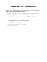
Minimum Clearances To Combustible Construction
8”
Boiler
Rear
Front
Control Side
Opposite Side
1”
(26MM)
11”
(280MM)
1”
(26MM)
1”
(26MM)

9
Table 4 -
Required Clearances
Unit
Combustible
Clearance
Accessibility,
Cleaning, and
Servicing
Top 1” (26mm) 8” (204mm)
Left Side 1 “ (26mm) -
Right Side 11” (280mm) -
Base 1” (26mm) -
Front 1” (26mm) 24” (610mm)
Back 1” (26mm) -
Intake/Vent Piping 0 (0) -
All distances measured from the cabinet of the boiler.
Locating The Boiler
1.
Place crated boiler as close to selected location as
possible and un-crate boiler. Boiler may be moved into
position with appliance dolly or 2 wheel hand truck.
Insert dolly or hand truck under left hand side of
boiler. It is possible to slide boiler for short distance on
smooth fl oor or surface.
2.
Select level location central to piping systems served
and as close to vent and air intake terminals as
possible.
3.
Accessibility clearances, if more stringent (i.e. larger
clearances) than required fi re protection clearances,
must be used for boiler installation. Accessibility
clearances may be achieved with the use of removable
walls or partitions.
4.
Boiler is approved for installation in closets and on
combustible fl oors. This boiler shall NOT be installed on
carpeting.
5.
Clearances shown in Table 4
indicate required
clearances. Maintain minimum 1” clearance between
combustible construction and each of left, top and
back surfaces of the boiler. Minimum 11” clearance is
required on right side, to allow room for induced draft
blower. Allow 24” at front and 8” at top for servicing.
No clearances are required to venting or combustion air
intake piping.
6.
Install equipment in location which facilitates operation
of venting and combustion air intake piping systems
as described in this manual. Draft inducer (blower)
may be rotated 90° or 180° to orient vent connections
towards right side or rear. Remove blower mounting
screws. Orient blower and install mounting screws. Do
not overtighten screws.
7.
Advise owner to keep venting and combustion air
intake passages free of obstructions. Both venting
and combustion air intake piping systems connected
to outdoors must permit fl ow through piping systems
without restrictions for boiler operation.
8.
Install boiler such that the automatic gas ignition
system components are protected from water
(dripping, spraying, rain, etc.) during operation and
service (circulator replacement, condensate trap,
control replacement, etc.).
9.
Keep boiler area clean of debris and free of fl ammable
and combustible materials, vapors and liquids.
10.
Locate boiler where minimum possible room
temperature where boiler is installed, assuming boiler
is not in operation and therefore contributes no heat
to space, is always at or above 32°F (0°C) to prevent
freezing of liquid condensate.
Combustion Air And Vent Pipe Requirements
This boiler requires a dedicated direct vent system. In a
direct vent system, all air for combustion is taken directly
from outside atmosphere, and all fl ue products are
discharged to outside atmosphere.
Terminate combustion air and vent pipe connections in
same atmospheric pressure zone, through roof or sidewall
(roof termination preferred). See Figure 12 thru Figure 14 ,
pages 24 and 25 for required clearances.
WARNING
Solvent cements are combustible. Keep away from
heat, sparks, and open fl ame. Use only in well
ventilated areas. Avoid breathing in vapor or allowing
contact with skin or eyes. Failure to follow these
instructions could result in fi re, serious injury, or death.
!
• Combustion air must be clean outdoor air. Combustion
air must not be taken from inside structure because
that air frequently is contaminated by halogens, which
include fl uorides, chlorides, phosphates, bromides
and iodides. These elements are found in aerosols,
detergents, bleaches, cleaning solvents, salts, air
fresheners, paints, adhesives and other household
products.
• Locate combustion air inlet as far away as possible
from swimming pool and swimming pool pump house.
• All combustion air and vent pipes must be airtight and
watertight. Combustion air and vent piping must also
terminate as shown in
“Combustion Air and Vent
Pipe”
section.
• Vent connections serving appliances vented by
natural draft shall not be connected into any portion
of mechanical draft systems operating under positive
pressure.
BOILER INSTALLATION
/