
Q95M-200
GAS-FIRED DIRECT VENT
MODULATING HOT WATER BOILER
INSTALLATION, OPER ATION &
MAINTENANCE MANUAL
An ISO 9001-2008 Certied Company
Manufactured by:
ECR International, Inc.
2201 Dwyer Avenue, Utica NY 13501
web site: www.ecrinternational.com
P/N# 240006103D, Rev. E [02/2014]
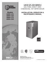
Model
Q95M-200

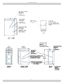
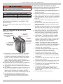
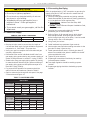
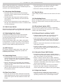
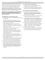
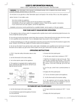
1 - DIMENSIONS
OPENING FOR
SAFETY
RELIEF VALVE
DISCHARGE PIPE
30⅞”
(785mm)
39⅜”
(1.1m)
18”
(458mm)
2

1 - Dimensions ..............................................................................................................2
2 - Introduction .............................................................................................................3
3 - Important Safety Information .....................................................................................4
4 - Boiler Ratings & Capacities .........................................................................................5
5 - Before Installing The Boiler ........................................................................................6
6 - Locating The Boiler ...................................................................................................7
7 - Near Boiler Piping .....................................................................................................9
8 - Combustion Air And Vent Pipe .................................................................................. 12
9 - Gas Supply Piping ................................................................................................... 17
10 - Electrical Wiring .................................................................................................... 19
11 - Controls And Accessories ....................................................................................... 21
12 - Boiler Startup ....................................................................................................... 23
13 - Operating Instructions ........................................................................................... 24
14 - Maintenance And Cleaning ..................................................................................... 25
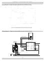
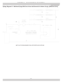
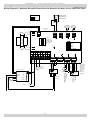
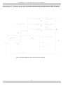
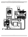
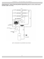
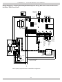
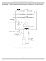
Appendix A - Boiler Piping And Wiring ............................................................................ 27
Appendix B - Water Quality, Water Treatment and Freeze Protection ................................... 45
2.1 Introduction
• Boiler is certied in accordance with ANSI Z21.13
American National Standards Institute) and CSA
(Canadian Standards Association) 4.9.
• This appliance is a gas-red direct vent modulating cast
aluminum hot water boiler.
• Cast aluminum monoblock heat exchanger allows better
heat transfer and thermal storage than similarly sized
cast iron boilers resulting in higher efciency.
• The heating system water absorbs large amounts of
heat from the cast aluminum heat exchanger, cooling
ue gases and causing condensation.
• Sealed combustion, premix gas burner, and low ame
temperature means reduced CO and NOx emissions,
which contribute to cleaner and healthier environment.
• This appliance takes its combustion air directly from
outdoors (sealed combustion) and does not compete
with building occupants for fresh air.
2 - INTRODUCTION
• Sealed combustion (also known as “direct vent”)
is safest and best way to obtain plenty of clean
combustion air.
• Forced draft fan draws in outside combustion air, takes
cooler ue gases from boiler unit and provides positive
removal of ue gases from the building through readily
available PVC and CPVC pipes. Canada use ULC S636
Material.
• These low pressure gas-red hot water boilers are
design certied by CSA International for use with
natural gas and propane gas.
• Boilers are constructed and hydrostatically tested
for maximum working pressure of 50 psig (pounds
per square inch gage) in accordance with A.S.M.E.
(American Society of Mechanical Engineers) Boiler and
Pressure Vessel Code Section IV Standards for heating
boilers.
3

3 - IMPORTANT SAFETY INFORMATION
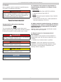
NOTICE
Used to address practices not related to personal
injury.
CAUTION
Indicates a hazardous situation which, if not avoided,
could result in minor or moderate injury.
!
WARNING
Indicates a hazardous situation which, if not avoided,
could result in death or serious injury.
!
DANGER
Indicates a hazardous situation which, if not avoided,
WILL result in death or serious injury
!
This is the safety alert symbol. Symbol alerts you to
potential personal injury hazards. Obey all safety messages
following this symbol to avoid possible injury or death.
Become familiar with symbols identifying
potential hazards.
3.1 General
Boiler installation shall be completed by qualied agency.
See glossary for additional information.
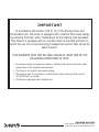
WARNING
Fire, explosion, asphyxiation and electrical shock
hazard. Improper installation could result in death or
serious injury. Read this manual and understand all
requirements before beginning installation.
!
Keep this manual near boiler
Retain for future reference
3.2 Installation shall conform to requirements of
authority having jurisdiction or in absence of such
requirements:
•
United States
• National Fuel Gas Code, ANSI Z223.1/NFPA 54
.
• National Electrical Code, NFPA 70.
• Canada
• Natural Gas and Propane Installation Code, CAN/CSA
B149.1. and .2
• Canadian Electrical Code, Part I, Safety Standard for
Electrical Installations, CSA C22.1
3.3 Where required by authority having jurisdiction,
installation shall conform to Standard for Controls
and Safety Devices for Automatically Fired Boilers,
ANSI/ASME CSD-1.
Additional manual reset low water cutoff and/or manual
reset high limit may be required.
3.4 Requirements for Commonwealth of
Massachusetts:
Boiler installation must conform to Commonwealth of
Massachusetts code 248 CMR which includes but is not
limited to:
• Installation by licensed plumber or gas tter.
Installers - Follow local regulations with respect to
installation of CO (Carbon Monoxide) Detectors. Follow
maintenance recommendations “Maintenance And
Cleaning” Section 14 page 25.
4

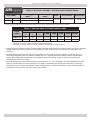
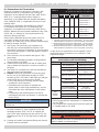
TABLE 1: SEA LEVEL RATINGS - NATURAL AND PROPANE GASES
Input (MBH)
(1)
Heating Capacity
(MBH)
(1)(2)
Net AHRI Rating
(MBH)
(1)
AFUE
(2)
Flue Diameter Shipping Wt.
High Fire 200 182 158
92.5% 2” CPVC & 3” PVC 284 lbs.
Low Fire 80 73 63
(1)
1 MBH = 1,000 BTUH (British Thermal Units Per Hour)
(2)
Heating Capacity and AFUE (Annual Fuel Utilization Efciency) are based on DOE (Department of Energy) test procedures.
TABLE 2: 95M-200 HIGH ALTITUDE DERATE CHART
Input
(MBH)
Altitude (In Feet)
3,000
(2)
4,000
(2)
5,000
(3)
6,000 7,000 8,000 9,000 10,000
High Fire 196 192 177 174.5 172 169 168 167
Low Fire 78.4 76.8 115 113.5 112 110 109 108
1)
Boiler Input Rate is determined at minimum vent length. The rate will decrease as vent length increases.
2)
Parameter 17 is set to 2,250 at elevations of 2,000 feet and below.
3)
Parameter 17 must be raised to 3,200 at altitudes or elevations of 2,000 feet and above.
• Heating Capacity indicates amount of heat available after subtracting losses up the stack. Most of this heat is available
to heat water. Small portion is heat loss from jacket and boiler surfaces, and it is assumed this heat stays in the
structure.
• Net AHRI Rating represents portion of remaining heat that can be applied to heat radiation or terminal units (i.e.,
nned tube baseboard, cast iron radiators, radiant oor, etc.) Difference between Heating Capacity and Net AHRI
Rating, called piping and pickup allowance, establishes reserve for heating volume of water in the system and
offsetting heat losses from piping.
• Net AHRI Ratings shown are based on piping and pickup factor of 1.15 in accordance with AHRI Standard. Net AHRI
Rating of selected boiler should be greater than or equal to calculated peak heating load (heat loss) for building or
area(s) served by boiler and associated hot water heating systems. Consult manufacturer before selecting boiler for
installations having unusual piping and pickup requirements.
4 - BOILER RATINGS & CAPACITIES
5

5.2 Boiler Sizing
• Verify you have selected boiler with proper capacity
before continuing installation. AHRI Rating of selected
boiler should be greater than or equal to calculated
peak heating load (heat loss) for the building or area(s)
served by boiler and associated hot water heating
systems. See Sea Level Ratings - Natural and Propane
Gases” Section 4.
• Heat loss calculations should be based on approved
industry methods.
5.3 Considerations for Boiler Location
Before selecting boiler location consider following.
• Supplied with correct type of gas (natural gas or
propane).
• Connected to suitable combustion air intake piping
system to supply correct amounts of fresh (outdoor) air
for combustion (15’ minimum equivalent length/100’
maximum equivalent length).
• Connected to suitable venting system. (15’ minimum
equivalent length/100’ maximum equivalent length).
• Connected to suitable hot water heating system.
• Supplied with suitable electrical supply for all boiler
motors and controls.
• Connected to properly located thermostat or operating
control (not included with boiler).
WARNING
Fire hazard. Do not install on carpeting. Failure to
follow these instructions could result in death or
serious injury.
!
• Placed on level surface (must NOT be installed on
carpeting).
• Pitch condensate drain line down to oor drain or
external condensate pump with reservoir at ¼” per foot
(wood frame or blocks may be used to raise boiler).
5.1 Before Boiler Installation
1.
Boiler is equipped for residential installations. If
used for commercial applications, additional code
requirements must be adhered to for installation. This
may require additional controls including but not limited
to a low water cut off, a manual reset high temperature
limit, and wiring and/or piping modications.
2.
Never vent products of combustion from this boiler to
enclosed space. Always vent to outdoors. Never vent to
another room or to inside building.
3.
Keep boiler area clean of debris and free of combustible
and ammable materials.
4.
Proper through wall or through roof combustion venting
shall be in accordance with materials and methods
described in this manual. Installation must comply with
local codes.
5 - BEFORE INSTALLING THE BOILER
6

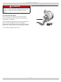
6.1 Locating the Boiler
1.
Place crated boiler as close to selected location as
possible and un-crate boiler. Boiler may be moved into
position with appliance dolly or 2 wheel hand truck.
Insert dolly or hand truck under right hand side of
boiler. It is possible to slide boiler for short distance on
smooth oor or surface.
2.
Select level location central to piping systems served
and as close to vent and air intake terminals as
possible.
3.
Accessibility clearances, if more stringent (i.e. larger
clearances) than required re protection clearances,
must be used for boiler installation. Accessibility
clearances may be achieved with use of removable
walls or partitions.
WARNING
Fire hazard. Do not install on carpeting. Failure to
follow these instructions could result in death or
serious injury.
!
4.
Boiler is approved for installation in closets and on
combustible oors. Boiler shall NOT be installed on
carpeting.
5.
Clearances shown in Table 3 indicate required
clearances per CSA listing. Minimum 1” (26mm)
clearance must be maintained between combustible
construction and each of the right, top and back
surfaces of the boiler. Allow at least 24” (610mm) at
front and left side and 8” (204mm) at top for servicing.
No combustible clearances are required to venting or
combustion air intake piping.
6.
Install equipment in location which facilitates operation
of venting and combustion air intake piping systems as
described in this manual.
7.
Advise owner to keep venting and combustion air
intake passages free of obstructions. Both venting
and combustion air intake piping systems connected
to outdoors must permit ow through piping systems
without restrictions for boiler to operate.
8.
Install boiler so automatic gas ignition system
components are protected from water (dripping,
spraying, rain, etc.) during operation and service
(circulator replacement, control replacement, etc.).
9.
Keep boiler area clean of debris and free of ammable
and combustible materials, vapors and liquids.
10.
Locate boiler where ambient room temperatures
(minimum possible temperatures where boiler is
installed assuming boiler is not in operation and
therefore contributes no heat to space) are always
at or above 32°F (0°C) to prevent freezing of liquid
condensate.
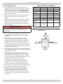
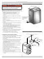
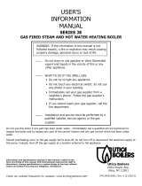
Figure 1 - Minimum Clearances To Combustible
Construction
8”
Boiler
Rear
Front
Right Side
Left Side
1”
(26mm)
1”
(26mm)
6”
(153mm)
0”
(0mm)
TABLE 3: BOILER CLEARANCES
Dimension
Combustible
Construction
Accessibility/
Cleaning
Service
Top
1” (26mm) 8” (204mm) 8” (204mm)
Left Side
1” (26mm) 24” (610mm) 24” (610mm)
Right Side
1” (26mm) - -
Base
Combustible - -
Front
0 24” (610mm) 24” (610mm)
Back
6” (153mm) - -
Intake/Vent
Piping
0 - -
Near Boiler
Hot Water
Piping
1” (26mm) - -
6 - LOCATING THE BOILER
7

6.2 Combustion Air and Vent Pipe Requirements
• This boiler requires dedicated direct vent system.
• In direct vent system all air for combustion is taken
directly from outside atmosphere, and all ue products
are discharged to outside atmosphere.
• Combustion air and vent pipe connections must
terminate together in same atmospheric pressure
zone, either through roof or sidewall (roof termination
preferred). See Figures 5 and 6 for required clearances.
For proper set up of concentric vent termination see
Figure 7 and Figure 8.
WARNING
Solvent cements are combustible. Keep away from
heat, sparks, and open ame. Use only in well
ventilated areas. Avoid breathing in vapor or allowing
contact with skin or eyes. Failure these instructions
could result in re, personal injury, or death.
!
• Locate combustion air inlet as far away as possible
from swimming pool and swimming pool pump house.
• All combustion air and vent pipes must be airtight and
watertight. Combustion air and vent piping must also
terminate as shown in “Combustion Air and Vent Pipe”
section.
• Vent connections serving appliances vented by
natural draft shall not be connected into any portion
of mechanical draft systems operating under positive
pressure.
• Covering non-metallic vent pipe and ttings with
thermal insulation shall be prohibited.
6 - LOCATING THE BOILER
6.3 Condensate Drain Requirements
• Condensate trap provided with boiler, an additional
trap is not required and should not be used.
• Pitch condensate drain line down to oor drain at
minimum of ¼” per foot. External condensate pump
(not furnished) may be used if oor drain is not
available.
• Condensate pump must be designed for ue gas
condensate application.
• Wood frame or blocks may be used to raise boiler
to maintain drain pitch or to be above external
condensate pump reservoir.
• If boiler is not level, condensate drain lines will not
function properly. Adjustable feet are located on boiler
to make up for minor surface irregularities or tilt.
• 115 volt AC receptacle provided on control panel to
provide power for external condensate pump if used.
6.4 Removal of Existing Boiler From Common
Vent System
When an existing boiler is removed from a common
venting system, the common venting system is likely to be
too large for proper venting of the appliances remaining
connected to it. At the time of removal of an existing boiler,
the following steps shall be followed with each appliance
remaining connected to the common venting system
placed in operation, while the other appliances remaining
connected to the common venting system are not in
operation.
1.
Seal any unused openings in the common venting
system.
2.
Visually inspect the venting system for proper size and
horizontal pitch and determine there is no blockage, or
restrictions, leakage, corrosion and other deciencies
which could cause an unsafe condition.
3.
In-so-far as is practical, close all building doors and
windows and all doors between the space in which the
appliances remaining connected to the common venting
system are located and other spaces of the building.
Turn on clothes dryer and any appliance not connected
to the common venting system. Turn on any exhaust
fans, such as range hoods and bathroom exhaust, so
they will operate at maximum speed. Do not operate a
summer exhaust fan. Close re dampers.
4.
Place in operation the appliance being inspected.
Follow the lighting instructions. Adjust thermostat so
appliances will operate continuously.
5.
Test for spillage at the draft hood relief opening after 5
minutes of main burner operation. Use the ame of a
match or candle, or the smoke from a cigarette, cigar
or pipe.
6.
After it has been determined that each appliance
remaining connected to the common venting system
properly vents when tested as outlined above, return
doors, windows, exhaust fans, re place dampers,
and any other gas-burning appliance to their previous
condition of use.
7.
Any improper operation of the common venting system
should be corrected so the installation conforms with
the National Fuel Code, NFPA-54/ANSI -Z223.1 and/or
the Natural Gas and Propane Installation Code, CAN/
CSA B149.1. When re-sizing any portion of common
venting system, common venting system should be re-
sized to approach minimum size as determined using
appropriate tables in Chapter 13 of the National Fuel
Gas Code, NFPA-54/ANSI- Z223.1 and/or the Natural
Gas and Propane Installation Code, CAN/CSA B149.1.
8

7.2 Supply & Return Lines
See Appendix A for piping examples.
• Packaged boiler set to receive 1¼” NPT return piping
from rear of unit with option for left or right return
connections.
• Use two furnished dielectric unions at boiler supply and
return connections between copper system piping and
boiler. Do not install copper supply and return piping
directly into aluminum boiler casting due to galvanic
corrosion between dissimilar metals.
• 1¼” NPT supply piping exits boiler jacket at top of unit.
• Some boilers supplied with circulator pump and
isolation valves are furnished in a carton inside boiler
cabinet and can be installed at installer preferred
location.
7.1 Clean System First
Before
connecting boiler to heating system, clean and ush
system thoroughly. Verify system is free of sediment, ux
and any residual boiler water additives.
Systems having antifreeze not recommended must be
completely ushed to insure no old antifreeze remains. In
older systems obviously discolored, murky or dirty water;
or pH reading outside acceptable range (between 7.0 and
8.0) are indications system should be cleaned or treated.
Thoroughly ush system with clean water to remove any
sediment or contaminants. Sludge and iron oxide deposits
can cause rapid breakdown of inhibitors.
Flushing with clean water. If chemical cleaners are used,
use only those recommended for use with aluminum
boilers. Follow chemical cleaner manufacturer’s instructions
completely.
DO NOT
mix different manufacturer’s products.
• When boiler installation is for new heating system,
install all of radiation units (panels, radiators,
baseboard, or tubing) and supply and return mains.
• After all heating system piping and components have
been installed, make nal connection of system piping
to boiler.
• Hot water boiler installed above radiation level, or as
required by the Authority having jurisdiction, must be
equipped with low water cut off device. This boiler is
factory equipped with manual reset probe type low
water cutoff.
• Periodic inspection is necessary per low water cut off
manufacturers specic instructions.
7 - NEAR BOILER PIPING
9

7 - NEAR BOILER PIPING
7.3
Safety Relief Valve / Temperature Pressure Gauge
WARNING
Burn and scald hazard. Safety relief valve could
discharge steam or hot water during operation.
Install discharge piping per these instructions.
!
Installation of (supplied) safety relief valve shall conform to
ANSI/ASME Boiler and Pressure Vessel Code, Section IV.
• Install furnished safety relief valve using 3/4” pipe
ttings provided with boiler. See Figure 2.
• Install safety relief valve with spindle in vertical
position.
• Do not install shutoff valve between boiler and safety
relief valve.
• Install discharge piping from safety relief valve. See
Figure 2.
• Use ¾” or larger pipe.
• Use pipe suitable for temperatures of 375°F (191°C) or
greater.
• Individual boiler discharge piping shall be independent
of other discharge piping.
• Size and arrange discharge piping to avoid reducing
safety relief valve relieving capacity below minimum
relief valve capacity stated on rating plate.
• Run pipe as short and straight as possible to location
protecting user from scalding.
• Install union, if used, close to safety relief valve outlet.
• Install elbow(s), if used, close to safety relief valve
outlet and downstream of union (if used).
• Terminate pipe with plain end (not threaded).
7.4 Expansion Tank & Make-up Water
• Determine required system ll pressure, system design
temperature, and system water content.
• Boiler contains 2.6 gallons (US). Size expansion tank
accordingly.
• Consult expansion tank manufacturer for proper sizing
information. Connect properly sized expansion tank
(not furnished) as shown in Figure 3 for diaphragm
type expansion tank.
• Adjust tank air pressure on diaphragm type expansion
tanks to match system ll pressure.
• Install air vent (furnished) as shown for diaphragm
type expansion tank system only.
• Install make-up water connections as show.
• If pressure reducing valve is used, adjust to match
system ll pressure.
• Verify clean water supply is available when connecting
cold make-up water supply to boiler.
• Use sand strainer at pump if water supply is from well
or pump.
GATE VALVE
REDUCED PRESSURE
BACKFLOW PREVENTER
FEED
WATER
PRESSURE
REDUCING VALVE
AIR SCOOP
DIAPHRAGM TYPE
EXPANSION TANK
SUPPLY PIPING
Check local codes
for maximum
distance from
oor.
FLOOR
Safety Relief Valve
Figure 2 - Safety Relief Valve Discharge Piping
Figure 3 -
Diaphragm Type Expansion Tank Piping
10

7.5 Condensate Drain Piping
Boiler is factory equipped with a condensate trap.
Additional trap is not required and should NOT be used.
• Use supplied 1/2” PVC tee, transition to ½” pipe and
ttings for PVC condensate drain line.
• The ½” diameter schedule 40 PVC or CPVC condensate
drain and pipe ttings must conform to ANSI standards
and ASTM D 1785 or D2846.
• Schedule 40 PVC or CPVC cement and primer must
conform to ASTM D2564 or F493. In Canada, use
CSA or ULC certied schedule 40 PVC drain pipe and
cement.
• Condensate pump with reservoir (not furnished) to
remove condensate to drain line (sanitary line) above
boiler if oor drain is not available or is inaccessible.
7.6 Filling Condensate Trap with Water
On initial start up manually ll condensate trap with water.
Following are steps required to initially ll condensate trap
for start up. Steps are only required at initial start up or if
maintenance requires draining of condensate trap.
1.
Remove vent drain line from CPVC vent pipe. Pour
about 1 cup of cold tap water into vent drain line.
2.
Excess water should go through overow and out
through condensate drain line. Verify proper operation
of drain line (or external condensate pump if used).
3.
Reinstall vent drain line.
7.7 Chilled Water Piping
Install Boiler, when used in connection with refrigeration
system, so chiller medium is piped in parallel with boiler
with appropriate valves to prevent chilled medium from
entering boiler.
Piping system of hot water boiler connected to heating coils
located in air handling units where they may be exposed
to refrigerated air circulation must be equipped with ow
control valves or other automatic means to prevent gravity
circulation of boiler water during cooling cycle.
7 - NEAR BOILER PIPING
11

8 - COMBUSTION AIR AND VENT PIPE
8.1 Connections And Termination
Boilers for connection to gas vents or chimneys, vent
installations shall be in accordance with “Venting of
Equipment” of the National Fuel Gas Code, ANSI Z223.1/
NFPA 54, or “Venting Systems and Air Supply for
Appliances”, of the Natural Gas and Propane Installation
Code, CAN/CSA B149.1, or applicable provisions of local
building codes.
Provisions for combustion and ventilation air must be
in accordance with section, Air For Combustion and
Ventilation, of the National Fuel Gas Code, ANSI 2223.1/
NFPA54, National Gas and Propane Installation Code, CAN/
CGA-B 149.1, in absence of such requirements to the
Authority having jurisdiction.
Boilers require dedicated direct vent system. All air for
combustion is taken directly from outdoors through
combustion air intake pipe. All ue products are discharged
to outdoors through vent pipe.
1.
See Figures 5 and 6 for two pipe combustion air
and vent pipe roof and sidewall termination. Roof
termination is preferred. Combustion air and vent pipes
must terminate together in same atmospheric pressure
zone as shown.
2.
Use of concentric vent termination see Figures 7-9for
proper setup.
3.
For Canadian installations all plastic venting material
must be listed to ULC S636.
4.
Construction through which vent and air intake pipes
may be installed is maximum 24 inches, minimum ¼”
thickness.
5.
See Table 5 for combustion air and vent pipe ttings
approved material and standards.
6.
Canada construct all combustion air and vent pipes
for this unit of ULC S636 listed schedule-40 CPVC,
schedule-40 PVC, PVC-DWV or ABS-DWV pipe and pipe
cement. SDR pipe is not approved in Canada.
• First 3 feet (900mm) of venting must be readily
available for visual inspection.
• Specied primers and glues of certied vent
system must be from single manufacturer, and not
intermixed with other manufacturer’s vent system
parts.
• Components of the certied system must not be
interchanged with other vent systems, or unlisted pipe
and/or ttings.
NOTICE
Transition from 2” pipe to 3” pipe must be made in
vertical run.
7.
Boiler combustion air and vent pipe connections are 2”
but must increase to 3”. Due to potential for ue gas
temperatures above 155°F, rst 30” of supplied vent
pipe is CPVC while remaining vent pipe can be PVC. Any
replacement of rst 30” of vent pipe must be made with
CPVC.
8.
Covering non-metallic vent pipe and ttings with thermal
insulation shall be prohibited.
TABLE 4
Maximum Allowable Temperatures
Of Typical Non-Metallic Vent Material
Material
HDT
RTI
Standard
°F °C °F °C
PVC 158 70 – –
ASTM F 891 *
ASTM D2665 **
ASTM D1785 **
ASTM D2241 **
CPVC 210 100 – –
ASTM D2846 **
ASTM F441 **
ASTM F442 **
ABS 180 82 – –
ASTM D2661 ***
ASTM F628 ***
* Allowable temperatures based on Classications covered in ASTM
D4396 [Deection Temperatures under Load (264psi) (1819 KPa)].
** Allowable temperatures based on Classications covered in ASTM
D1784 [Deection Temperatures under Load (264psi) (1819 KPa)].
*** Allowable temperatures based on Classications covered in ASTM
D3965 [Deection Temperatures under Load (264psi) (1819 KPa)].
Length of pipe is counted from end of supplied 2” CPVC
pipe exiting boiler. Termination is not counted in “Total
Equipment Length.”
Table 5 - Combustion air and vent pipe ttings
must conform with the following:
Item Material Standards
Vent Pipe
and Fittings
PVC schedule 40 ANSI/ASTM D1785
PVC - DWV ANSI/ASTM D2665
CPVC schedule 40
ANSI/ASTM D1784/
F441
SDR-21 & SDR-26 PVC ANSI/ASTM D2241
ABS-DWV ANSI/ASTM D2661
Schedule 40ABS ANSI/ASTM F628
PP (Polypropylene)
Pipe and Components
UL 1738
ULC S636-08
Pipe
Cement/
Primer
PVC ANSI/ASTM D2564
CPVC ANSI/ASTM F493
Schedule 40 ABS ANSI/ASTM D2235
• IPEX is approved vent manufacturer in Canada listed
to ULC-S636.
• IPEX System 636 Cements and Primers are approved
in Canada listed to ULC-S636.
Use of cellular core PVC (ASTM F891), cellular core CPVC, or Radel
®
,
(Polyphenolsulfone) in venting systems shall be prohibited.
WARNING
Use of cellular core PVC for venting ue gas could
result in death, or serious injury.
!
12

8 - COMBUSTION AIR AND VENT PIPE
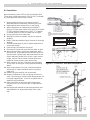
Allowable Vent and Air Intake Lengths
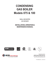
3” Pipe Min. Length 3” Pipe Max. Length
15 ft. equivalent length 100 ft. equivalent length
FIELD INSTALL 2” BY 3”
TRANSITION IN THE
VERTICAL POSITION
ONLY (2 REQ’D, NOT
FURNISHED)
3” INTAKE AND
EXHAUST
TERMINATIONS
2” (50.8MM)
CPVC
VENT PIPING
(FURNISHED &
REQUIRED)
2” (50.8MM)
COMBUSTION AIR
INTAKE PIPING
(FURNISHED)
Figure 4 - Combustion Air & Vent Piping
9.
Combustion air must be clean outdoor air. Do not take
combustion air from inside structure because that air
is frequently contaminated by halogens, which includes
uorides, chlorides, phosphates, bromides and iodides.
These elements are found in aerosols, detergents,
bleaches, cleaning solvents, salts, air fresheners, paints,
adhesives, and other household products.
10.
Locate combustion air inlet as far away as possible from
swimming pool and swimming pool pump house.
11.
All combustion air and vent pipes must be airtight and
watertight.
12.
Pitch exhaust air piping back to boiler at minimum ¼” per
foot from vent terminals so all moisture in vent piping
drains to boiler. Pitch pipes with no sags or low spots
where moisture can accumulate and block ow of ue gas.
13.
Vent connections serving appliances vented by
natural draft shall not be connected into any portion
of mechanical draft systems operating under positive
pressure.
8.2 Vent/Air Intake Termination Location
Consider following when determining appropriate location
for termination of combustion air and vent piping.
A. Position termination where vent vapors will not
damage plants/shrubs, air conditioning equipment, or
siding on the house.
B. Position termination so it will not be effected by wind
eddy, air born leaves, snow, or recirculated ue gases.
C. Position termination where it will not be subjected to
potential damage by foreign objects, such as stones,
balls, etc.
D. Position termination where vent vapors are not
objectionable.
E. Put vent on wall away from prevailing winter wind.
Locate or guard vent to prevent accidental contact
with people or pets.
F. Terminate vent above normal snow-line. Avoid locations
where snow may drift and block vent. Ice or snow may
cause boiler to shut down if vent becomes obstructed.
G. Under certain conditions, ue gas will condense,
forming moisture, and may be corrosive. In such
cases, take steps to prevent building materials at
vent from being damaged by exhaust of ue gas.
H. United States - Terminate vent system at least 4
feet (1.22 m) horizontally from, and in no case
above or below, unless a 4 feet (1.22 m) horizontal
distance is maintained, from electric meters, gas
meters, regulators and relief equipment.
I. Canada - Terminate vent system at least 6 feet
(1.83m) horizontally from, and in no case above
or below, unless 6 feet (1.83m) horizontal distance
is maintained, from electric meters, gas meters,
regulators and relief equipment.
J. Terminate venting system at least 3 feet (0.3m)
above any forced air inlet (except boiler’s
combustion air inlet) within 10 feet (3m).
K. Terminate venting system at least 12 inches
(300mm) from any air opening into any building.
L. Locate bottom of vent at least 12 inches (300mm)
above grade.
M. Terminate vent not less than 7 feet (2.1m) above
adjacent public walkway.
N. Vent terminal shall not be installed closer than 3 feet
(0.9m) from inside corner of L shaped structure.
O. Termination of vent should be kept at least 3 feet
(0.9m) away from vegetation.
P. If multiple terminations are used, minimum of
12 inches (300 mm) between exhaust of one
termination and air intake of next termination. See
pages 14 & 15.
Q. All eld installed vent pipe must be 3”.
Length of pipe is counted from end of supplied 2” CPVC
pipe exiting boiler. Termination is not counted in “Total
Equivalent Length.”
Reduce maximum vent/air intake length by 5 feet per each
90° elbow.
WARNING
Covering non-metallic vent pipe and ttings with
thermal insulation shall be prohibited.
!
13

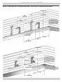
Figure 5 - Side Wall Vent / Intake terminations - Less Than 12” Clearance Above Grade
8 - COMBUSTION AIR AND VENT PIPE
3” MIN
SEPARATION
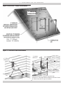
14

8 - COMBUSTION AIR AND VENT PIPE
Combustion
Air
Vent
1" (26mm)
Maximum
1" (26mm)
Maximum
Roof Overhang
* See Note
Below
Vent
Combustion
Air
36"(915mm) Minimum
Maintain 12"(300mm)
clearance above highest
anticipated snow level or
grade
12" (300mm) Minimum
*Must be less than 4" (102mm) or greater than
24"(610mm) Horizontal distance between end bells of each
air intake to prevent ue gas recirculation.
Figure 6 -Roof Vent / Intake Terminations
Figure 7 - Concentric Vent Terminations
3” MINIMUM
SEPARATION
15

8 - COMBUSTION AIR AND VENT PIPE
MAINTAIN 12 IN.
Figure 8 - Concentric Vent w/ Dimensions
Figure 9 - Concentric Vent Roof Installation
8.3 Installation
When transitioning from CPVC to PVC use Weld-On CPVC
724 or other cement approved for CPVC to PVC. In Canada
ULC S636 approved cement must be used.
1.
Recommend all pipes be cut, prepared, and pre-
assembled before permanently cementing any joint.
2.
Rigid supports cause excess noise in vent piping.
3.
Attach combustion air intake piping to supplied 2”
piping on CVI gas valve. Attach vent piping to furnished
2” CPVC preformed exhaust pipe. Use 2” x 3” adapter
in vertical position on both air intake and vent pipe.
4.
All pipe joints are to be water tight.
5.
Working from boiler to outside, cut pipe to required
length(s).
6.
Deburr inside and outside of pipe. Remove all chips and
shavings.
7.
Chamfer outside edge of pipe for better distribution of
primer and cement.
8.
Clean and dry all surfaces to be joined.
9.
Check dry t of pipe and mark insertion depth on pipe.
10.
After pipes have been cut and pre-assembled, apply
cement primer to pipe tting socket and end of pipe to
insertion mark. Quickly apply approved cement to end
of pipe and tting socket (over primer). Apply cement
in light, uniform coat on inside of socket to prevent
buildup of excess cement. Apply second coat.
11.
While cement is still wet, insert pipe into socket with
¼ turn twist. Be sure pipe is fully inserted into tting
socket.
12.
Wipe excess cement from joint. Continuous bead of
cement will be visible around perimeter of properly
made joint.
13.
Handle pipe joint carefully until cement sets.
14.
Support combustion air and vent piping minimum of
every 5 feet using pre-formed metal hanging straps. Do
not rigidly support pipes. Allow for movement due to
expansion and contraction.
15.
Slope combustion air and vent pipes toward boiler
minimum of ¼” per linear foot with no sags between
hangers.
16.
Use appropriate methods to seal openings where vent
and combustion air pipes pass through roof or side
wall.
A
B
C
3” Diameter PVC
Vent/Exhaust
1½”
4½” Dia.
31⅞”
A
A
B
B
C
C
D
E
F
G
G
3” Diameter PVC
Intake/Combustion Air
46¾”
Dimension
1
³⁄16
”
D
E
F
Dimension
16

9 - GAS SUPPLY PIPING
CAUTION
WHAT TO DO IF YOU SMELL GAS
• Do not try to light any appliance.
• Do not touch any electrical switch; do not use
any phone in your building.
• Immediately call your gas supplier from a
neighbor’s phone. Follow gas supplier’s
instructions.
• If you cannot reach your gas supplier, call the re
department.
!
9.1 Check Gas Supply
TABLE 6: GAS SUPPLY PRESSURE
Natural Gas 4” min. w.c. 10” max. w.c.
LP Gas 10” min. w.c. 14” max. w.c.
Check line pressure while unit is running in high re mode.
TABLE 7: GAS PIPING SIZES
Natural Gas
Pipe Length
Pipe Capacity - BTU/Hr. Input Includes Fittings
½” ¾” 1” 1¼”
20’ 92,000 190,000 350,000 625,000
40’ 63,000 130,000 245,000 445,000
60’ 50,000 105,000 195,000 365,000
LP Gas
Pipe Length
Pipe Capacity - BTU/Hr. Input Includes Fittings
Copper Tubing (O.D.) Iron Pipe
⅝” ¾” ½” ¾”
20’ 131,000 216,000 189,000 393,000
40’ 90,000 145,000 129,000 267,000
60’ 72,000 121,000 103,000 217,000
The length of pipe or tubing should be measured from the gas meter or
propane second stage regulator.
• Gas pipe to boiler must be correct size for length of
run and total Btuh input of all gas utilization equipment
connected to it.
See Table 7
for proper size.
• Verify your gas line complies with local codes and gas
company requirements.
• Disconnect boiler and its individual shutoff valve from
gas supply piping system during any pressure testing of
system at test pressures in excess of ½ psig (3.5kPa).
• Isolate boiler from gas supply piping system by closing
its manual shutoff valve during any pressure testing of
gas supply piping system at test pressures equal to or
less than ½ psig (3.5kPa).
• For proper boiler operation line pressure should be
within minimum and maximum values in Table 6.
• Gas line enters boiler through left side panel. See page
2 Dimensions and Figure 10.
Boiler is equipped with ½” NPT connection on gas valve for
supply piping and ½” NPT ball valve for manual shut off.
Following rules apply:
1.
Use only those piping materials and joining methods
listed as acceptable by the authority having jurisdiction,
or in the absence of such requirements,
• United States - National Fuel Gas Code, ANSI
Z223.1/NFPA 54.
• Canada - Natural Gas and Propane Installation Code,
CAN/CSA B149.1.
2.
Use pipe joint compound suitable for liqueed
petroleum gas on male threads only.
3.
Refer to Figure 10 for general layout, which shows
basic ttings needed. As shipped, gas line enters
boiler through right side, as an option, it can be routed
through either rear or left side panel.
4.
Use ground joint unions.
5.
Install sediment trap upstream of gas controls.
6.
Use two pipe wrenches when making connection to the
gas valve to keep it from turning.
7.
Install manual shutoff valve in vertical pipe about 5’
above oor outside boiler jacket in addition to shutoff
valve supplied with boiler.
8.
Tighten all joints securely.
9.
Propane gas connections should only be made by
licensed propane installer.
10.
Two stage regulation should be used by propane
installer.
11.
Propane gas piping should be checked by propane
installer.
9.2 Connecting Gas Piping
17

Figure 10 - Gas Piping
9.3 Leak Check Gas Piping
After making gas connections, open manual shutoff
valve(s) and check all gas connections for leaks before
placing boiler in operation.
Locate leakage using gas detector, noncorrosive detection
uid, or other leak detection method acceptable to
authority having jurisdiction. Do not use matches, candles,
open ames, or other methods providing ignition source.
Correct leaks immediately and retest.
9 - GAS SUPPLY PIPING
1/2” GAS CONNECTION
*NOTE: 3/4” GAS SUPPLY
TO BOILER JACKET
REQUIRED TO FEED
THE BOILER.
DANGER
Fire Hazard. Do not use matches, candles, open
ames, or other methods providing ignition source.
Failure to comply will result in death or serious
injury.
!
18

10.1 Codes
Electrically bond boiler to ground in accordance with
requirements of authority having jurisdiction. In absence
of such requirements, Refer to:
• USA - National Electrical Code, ANSI/NFPA 70.
• Canada - Canadian Electrical Code, Part I, CSA C22.1:
Safety Standard for Electrical Installations.
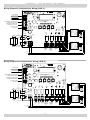
10.2 Line Voltage Connections
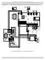
1.
Connect 120 VAC power wiring to line voltage terminal
strip on boiler control panel.
2.
Provide and install fused disconnect or service switch
(15 amp recommended) as required by code.
3.
Boiler circulator is shipped loose. Wire boiler circulator
as shown in wire diagram label on boiler side panel.
(CH L1, CH L2) CH = Central Heat
4.
When connecting DHW circulator, connect wiring to line
voltage terminal strip on boiler control panel. (DHW L1,
DHW L2) DHW = Domestic Hot Water
5.
Route all wires and conduits to openings in right jacket
panel.
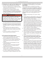
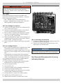
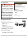
10.3 Line Voltage Monitor
• Boiler is factory equipped with line voltage monitor that
continuously monitors incoming voltage for errors.
• When incoming line voltage is greater than 12% or less
than 8% of nominal voltage monitor will ash indicating
fault.
• 6 Seconds after line voltage is back within acceptable
range green light will illuminate on monitor and boiler will
restart. Line voltage monitor is factory set at 115 VAC.
It is important that monitor be set to voltage present at
installation site by following these directions:
1.
Using multimeter, locate wall outlet nearest to boiler
and determine line voltage present on site.
2.
Disconnect power to boiler.
3.
Remove boiler cover.
4.
Locate line voltage monitor mounted to display panel.
5.
Remove line monitor protective cover.
6.
Using small screwdriver turn left dial until arrow points
at input voltage measured during step 1.
7.
Set right dial at 0.1 minute, this is factory setting.
8.
Reinstall line monitor protective cover.
9.
Replace boiler cover and re-connect power to unit.
WARNING
Electrical shock hazard. Turn OFF electrical power
supply at service panel before making electrical
connections. Failure to do so could result in death or
serious injury.
!
10 - ELECTRICAL WIRING
NOTICE
Use only N.E.C. Class 1 wiring. If replacing original
boiler wiring, use only type 105°C wire or equivalent.
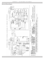
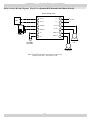
See Piping and Wiring Appendix for wiring
and piping diagrams.
Figure 11 - Line Voltage Monitor
10.4 Low Voltage Connections
1.
Connect low voltage wiring to low voltage terminal strip
as shown in boiler wiring diagram.
2.
Route all low voltage wires through opening on right
jacket panel. Use shielded cable.
L1 L2
19

10 - ELECTRICAL WIRING
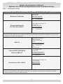
10.6 Thermostat
1.
Connect room thermostat or end switch (isolated
contact only) between terminals T1 and T2.
2.
Install thermostat on inside wall away from inuences
of drafts, hot or cold water pipes, lighting xtures,
televisions, sun rays, or replaces.
3.
Thermostat anticipator (if applicable)
A. Set for 0.1 amps if connected directly to boiler.
B. Set to match total electrical power requirements of
connected devices if connected to relays or other
devices. See device manufacturers’ specications
and thermostat instructions for details.
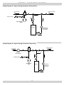
10.7 Outdoor Temperature Sensor
1.
Connect outdoor temperature sensor between terminals
A1 and A2 to enable outdoor reset operation of the
boiler. If xed temperature operation is required, do
not install outdoor sensor.
2.
Mount sensor on exterior wall, shielded from direct
sunlight or ow of heat or cooling from other sources.
3.
If desired, install a summer/winter switch across
terminals A1 and A2. When the switch is closed, the
boiler (space heating) circulator is disabled.
4.
Route sensor wires through the holes provided on the
right jacket panel of the boiler.
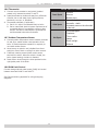
10.8 DHW Limit Control
Connect storage indirect water heater (DHW) limit control
between terminals DHW T1 and DHW T2.
See Piping and Wiring Appendix for wiring and piping
diagrams.
AVOID THE FOLLOWING
Dead Spots
Corners
Alcoves
Behind doors
Cold Spots
Concealed pipes or ducts
Stairwells - drafts
Unheated rooms on the other side
of the wall
Hot Spots
Concealed pipes
Fireplaces
TVs or radios
Lamps
Direct sunlight
Kitchens
20
Page is loading ...
Page is loading ...
Page is loading ...
Page is loading ...
Page is loading ...
Page is loading ...
Page is loading ...
Page is loading ...
Page is loading ...
Page is loading ...
Page is loading ...
Page is loading ...
Page is loading ...
Page is loading ...
Page is loading ...
Page is loading ...
Page is loading ...
Page is loading ...
Page is loading ...
Page is loading ...
Page is loading ...
Page is loading ...
Page is loading ...
Page is loading ...
Page is loading ...
Page is loading ...
Page is loading ...
Page is loading ...
Page is loading ...
Page is loading ...
Page is loading ...
Page is loading ...
-
 1
1
-
 2
2
-
 3
3
-
 4
4
-
 5
5
-
 6
6
-
 7
7
-
 8
8
-
 9
9
-
 10
10
-
 11
11
-
 12
12
-
 13
13
-
 14
14
-
 15
15
-
 16
16
-
 17
17
-
 18
18
-
 19
19
-
 20
20
-
 21
21
-
 22
22
-
 23
23
-
 24
24
-
 25
25
-
 26
26
-
 27
27
-
 28
28
-
 29
29
-
 30
30
-
 31
31
-
 32
32
-
 33
33
-
 34
34
-
 35
35
-
 36
36
-
 37
37
-
 38
38
-
 39
39
-
 40
40
-
 41
41
-
 42
42
-
 43
43
-
 44
44
-
 45
45
-
 46
46
-
 47
47
-
 48
48
-
 49
49
-
 50
50
-
 51
51
-
 52
52


UTICA BOILERS UB95M-200 Installation & Operation Manual
- Type
- Installation & Operation Manual
- This manual is also suitable for
Ask a question and I''ll find the answer in the document
Finding information in a document is now easier with AI
Related papers
-
 UTICA BOILERS Q90-100 Series IV Operating instructions
-
UTICA BOILERS UB95M-200 User manual
-
 UTICA BOILERS UB90-200 Installation & Operation Manual
-
UTICA BOILERS Q90-100 Series IV User manual
-
 UTICA BOILERS Q90-200 Series II User manual
-
 UTICA BOILERS JE User manual
-
 UTICA BOILERS 97gb High Efficiency Gas-Fired Modulating Condensing Boiler Convertible (Floor or Wall) Installation & Operation Manual
-
-
 UTICA BOILERS UB95M-200 Operation and Installation Manual
-
UTICA BOILERS MCB300 Installation, Operation & Maintenance Manual


Other documents
-
-
Dunkirk Q90-100 Series IV Installation & Operation Manual
-
Lennox International Inc. Water Dispenser Gas-Fired Hot Water Boiler User manual
-
-
Dunkirk Q90-100 Series IV Operating instructions
-
-
-
TRIANGLE TUBE HMG Delta Series Product information
-
-