
T9 THERMOSTAT
Installation Guide
Online Guides
honeywellhome.com
33-00421ES_A.indd 1 11/7/2018 10:37:43 AM

2
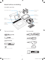
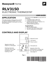
Read before installing.
Included in your box:
Tools you will need: You may need:
Installation Guide Screws and
anchors
Phillips screwdriver Wire Stripper
Home WiFi Password
Wireless
room sensor
T9 WiFi
Thermostat
Small flat head screwdriver
Needle-nose pliers
CWire
Adapter
(optional)
UWP
Wallplate
Pencil
Drill and drill bit (7/32in)
Wire labels
Level
Flashlight
33-00421ES_A.indd 2 11/7/2018 10:37:43 AM

3
Compatibility Section
For help, see:
ONLINE GUIDES AND SUPPORT VIDEOS AT: honeywellhome.com/support
SOCIAL Twitter: @Honeywell_Home, Facebook: Honeywell Home
Or contact:
EMAIL honeywellhomessupport@honeywell.com
PHONE 1-800-633-3991
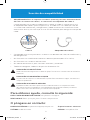
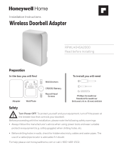
Electrical Specifications
INPUT: 24V~@60Hz, 0.2A
• REQUIRED: A CWire (common wire) is needed for 24 VAC power. If you do not
have a CWire, then a CWire Adapter is provided.
This guide will help you determine if you have a CWire or will need to use the
included CWire Adapter (Step 10). The CWire is a wire that originates from your
heating and cooling system and needs to be connected to the C terminal on your
thermostat. There is no universal color used to designate this type of wire.
CAUTION: ELECTRICAL HAZARD
Can cause electrical shock or equipment damage. Disconnect power before beginning installation.
CAUTION: EQUIPMENT DAMAGE HAZARD
Compressor protection is bypassed during testing. To prevent equipment damage, avoid cycling the
compressor quickly.
CAUTION: MERCURY NOTICE
If this product is replacing a control that contains mercury in a sealed tube, do not place the old control
in the trash. Contact your local waste management authority for instructions regarding recycling and
proper disposal.
• Compatible with most heating, cooling, and heat pump systems
• Does not work with electric baseboard heat (120240V)
• Does not work with millivolt systems
• Does not support S terminals for indoor and outdoor sensors
• Android or iOS smartphone, tablet, or device
C
C
U
GY
GY
A
OR
CWire CWire Adapter
33-00421ES_A.indd 3 11/7/2018 10:37:43 AM

4
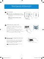
Removing your old thermostat
You will need: Screwdriver, needle-nose pliers
OFF
ON
75
1
2
3
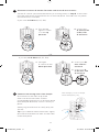
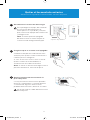
Turn off power
To protect your equipment, turn off
the power at the breaker box or switch
that controls you heating and cooling
equipment.
Note: The thermostat off switch
will not turn off the power to the
equipment.
Check that your system is off
Change the temperature on your old
thermostat so that your system starts
heating or cooling.
If you don’t hear or feel the system turn
on within 5 minutes, the power is off.
Note: If you have a digital thermostat that
has a blank display, skip this step.
Remove your existing thermostat from
the wall plate
On most thermostats, you can take off
the thermostat by grasping and gently
pulling. Some thermostats may have
screws, buttons, or clasps.
Do not remove any wires from your
thermostat at this time!
OR
OFF
Breaker box
Switch
33-00421ES_A.indd 4 11/7/2018 10:37:44 AM

5
5
6
7
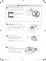
4
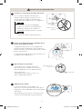
Take a picture of your existing wall
plate’s wiring
In order to capture all of the letters next
to the terminals, be sure to take multiple
pictures from different angles.
You may need to reference this image
later.
Remove any jumpers
A jumper is used to connect two
terminals. It may look like a small
staple or a colored wire.
Do not discard.
Keep jumpers with your old wallplate.
Label the wires
Use the stickers provided with your new
thermostat to label each wire on your
existing wall plate.
Do not label jumpers. Your new
thermostat does not need jumpers.
Do you have a line voltage system?
Line voltage systems have thick black
wires with wire nuts or are labeled high
voltage (120V or higher).
Your system is not compatible. Call
18557335465 to find a pro-
installer in your area.
Continue to the next step.
Wire nut
Thick black wire
Example
of a jumper
Terminals
Compatibility Check
YES
NO
Y
RRC
33-00421ES_A.indd 5 11/7/2018 10:37:44 AM

6
10
Do you have a CWire?
Look at the thermostat wiring
checklist from Step 8, or the photo
you took. Is the CTerminal checked?
This means you will not need
to install the included CWire
Adapter. Skip to Installing Your
New Thermostat (page 9).
This means you don’t have
a C-wire connected to your
thermostat. Continue to next
step.
Compatibility Check
YES
NO
9
8
Disconnect the wires and remove
the old wall plate
You may need a screwdriver to
release wires from terminals.
Tip: Wrap the wires around a pencil
to prevent them from falling in the
wall.
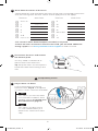
Write down the colors of the wires
Check the boxes and write down the color of the wires connected to terminals
that are coming from the wall. Check all that apply (not all will apply).
Terminal Wire Color Terminal Wire Color
¨
A or L/A
¨
R
¨
C Required*
¨
R
c
¨
E
¨
R
h
¨
G
¨
W
¨
K
¨
W2 or Aux
¨
O/B
¨
Y
¨
U (1 or 2)
¨
Y2
*A C-wire or CWire Power Adapter (included) is required.
If there are wires in terminals that are not listed, you will need additional
wiring support. Visit honeywellhome.com/support to find out more.
C
C
U
GY
GY
A
33-00421ES_A.indd 6 11/7/2018 10:37:45 AM

7
11
12
13
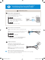
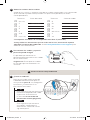
Do you have a zoning panel?
You have a zoning panel if you
have multiple thermostats and one
furnace or heating system.
CWire Adapter installation is
more complicated on zoned
systems. Call 18557335465
to find a pro-installer.
Proceed to the next step.
Do you have an unused wire?
Look at the bundle of wires coming from the
wall.
Note: You may have to pull the bundle of wires
out from the wall to find the unused wire.
Continue to Step 13.
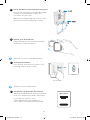
Open the included CWire Adapter box
and follow the instruction guide.
Label unused wire
Label your unused wire with the
provided “C” sticker label. You may need
to use a wire stripper to expose at least
1/4 inch of the wire.
Note: If you have multiple unused wires,
then label only one wire and make note
of the color here:
Compatibility Check
YES
YES
NO
NO
Only complete this section if you answered No to Step 10
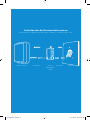
Connecting Your Unused CWire
You will need: Screwdriver, flashlight, wire strippers
Thermostat
Furnace
Example of unused C-wire
Zoning
Panel
-
Go to your furnace or heating system
This system is often located in your basement, attic or garage.
Bring a flashlight and screwdriver.
33-00421ES_A.indd 7 11/7/2018 10:37:45 AM

8
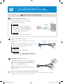
14
16
15
17
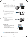
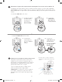
Remove cover from furnace or heating
system
Open the heating and cooling system’s
cover to find the control board. You
should see the same terminal labels that
are on your thermostat.
Note: You may need to unscrew the cover.
The control board may be at the top or
bottom.
Connect the unused wire to the
C-terminal
Note: If there are existing wires in the
C-terminal, make sure they are still
connected to the C-terminal after
connecting this wire.
Find the other end of the unused wire
Locate the bundle of wires that are the
same as the ones at your thermostat.
The unused wire should be the same
color as the one near your existing
thermostat. See Step 13 for the color you
wrote down.
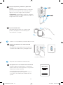
Close the cover to the furnace or
heating system
Be sure the cover is completely closed.
Some systems will not power up if the
cover isn’t fully closed.
You’ve connected the C-wire.
You will NOT need to use the included
CWire Adapter.
G
C
R
W
Y
G
C
R
W
Y
G
C
R
W
Y
-
Go back to the wall where you are installing your thermostat and continue
to “Installing Your New Thermostat” on the next page.
33-00421ES_A.indd 8 11/7/2018 10:37:46 AM

9
Installing Your New Thermostat
You will need: Level, pencil, drill and a 7/32in drill bit
Thermostat Screws UWP
wallplate
WallAnchors
33-00421ES_A.indd 9 11/7/2018 10:37:46 AM

10
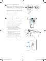
18
19
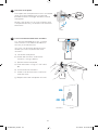
Position wall plate
Pull open the wall plate that was included
with your new thermostat. Insert the
bundle of wires through the back of the
wall plate.
Make sure at least 1/4-inch of each wire
is exposed for easy insertion into the wire
terminals.
Insert recommended wall anchors
It is recommended that you use the
wall anchors included in the box to
mount your thermostat.
You can use the wall plate to mark
where you want to place the wall
anchors.
a) Level the wall plate
b) Mark the location of the wall
anchors using a pencil
c) Remove the wall plate
d) Drill the holes using a 7/32” drill
bit
e) Insert the wall anchors
f) Make sure the anchors are flush
with the wall
g) Reposition the wall plate on wall
-
UWP
Anchors Wall
33-00421ES_A.indd 10 11/7/2018 10:37:46 AM

11
21
Connect remaining wires from Step 8
Push down on the tabs to put the
wires into the inner holes of their
corresponding terminals on the wall plate
(one wire per terminal) until it is firmly in
place.
Gently tug on the wires to verify they are
secure.
Tip: If you need to release the wires again,
push down the terminal tabs on the sides
of the wall plate.
1. Ensure the
right R-switch
is in the up
position.
1. Set right
R-switch to the
down position.
20
Determine Correct RSwitch Position and Insert R-wire or wires
Set the R-switch up or down based on your wiring notes in Step 8. Insert wires
into the inner holes of the terminals on the wall plate. The tabs will stay down
once the wire is inserted.
If you have 1 RWire (R, RC, RH):
If you have 2 RWires (R, RC, RH):
2. Insert your
R-wire (R, Rh
or Rc) into
R-terminal.
2. Insert your Rc
wire into Rc-
terminal.
3. Insert your R
or Rh wire into
R-terminal.
OR
This wiring is just an example,
actual wiring may vary.
33-00421ES_A.indd 11 11/7/2018 10:37:46 AM

12
22
23
24
25
Close the door and mount the wall plate
Mount the wall plate using the provided
screws. Install all three screws for a
secure fit on your wall.
Tip: Prior to tightening the screws, use a
level to ensure the wall plate is level.
Attach your thermostat
Align the thermostat on the wall plate
and firmly snap into place.
Turn power back on
Turn on the switch that controls your
heating and cooling system.
Complete setup on the thermostat
Remove the protective film and confirm
that your thermostat reads “Welcome.”
If you do not see this, visit
honeywellhome.com/support or
call 18557335465 for more help.
Go back to your circuit breaker box.
Go back to your thermostat.
OFF
ON
ON
Breaker box
Switch
Welcome!
33-00421ES_A.indd 12 11/7/2018 10:37:47 AM

13
Getting the most from the T9 WiFi Thermostat
Prioritize Rooms
Prioritize a specific room or multiple rooms, or let comfort follow your move using
built-in motion detection.
Control on the Go
Adjust your thermostat from anywhere using your tablet or smartphone.
Save Energy
With geofencing, you can save money on the most expensive part of your energy bill
while you’re away.
Simple Installation
The thermostat automatically programs itself. Just answer a few simple questions
and you’ll be up and running in no time.
WholeHome Range
With up to a 200-foot* range, 20 sensors with temperature, humidity, and occupancy
detection can connect to your thermostat from throughout your home.
*Range can vary based on home construction, wireless interference, and other
factors.
Know Your Home Is Safe
Get customizable alerts on your mobile device such as when the basement is so cold
a pipe could burst, or if the baby’s room is getting too hot.
33-00421ES_A.indd 13 11/7/2018 10:37:47 AM

14
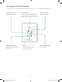
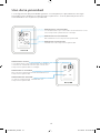
Using your thermostat
The screen will wake up by pressing the center area of the displayed temperature.
74
2
18%
Indoor Temperature
Displays the current
indoor temperature.
Adjust Temperature
Touch the up and down
arrows to set your desired
temperature.
Current Priority
Displays the type of priority and
number of rooms being prioritized.
Extend your thermostat’s reach with
additional Wireless Room Sensors.
Menu
Contains features such
as mode, fan, schedule,
priority, and other
thermostat settings.
Indoor Humidity
Displays the current
indoor humidity.
Desired Temperature
Displays the desired
temperature.
33-00421ES_A.indd 14 11/7/2018 10:37:47 AM

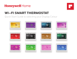
15
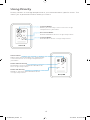
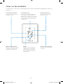
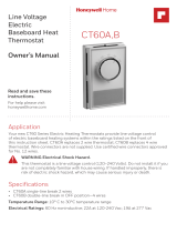
Using Priority
Priority creates an average temperature in your home based on specific rooms. This
allows you to prioritize comfort where you want it.
Selected Rooms
Rooms you manually select create an average
temperature in your home.
Unselected Room
Will not contribute to the average temperature.
Selected Room
Will contribute to the average temperature.
72 72
72 72
72 72
72 72
Active Rooms
Rooms with detected motion are automatically
selected to create an average temperature in
your home.
Room without Activity
No motion is detected. Will not contribute to
the average temperature.
Room with Activity
Motion is detected. Will contribute to the
average temperature.
33-00421ES_A.indd 15 11/7/2018 10:37:47 AM

16
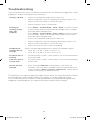
Troubleshooting
If you have difficulty with your thermostat, please try the following suggestions. Most
problems can be corrected quickly and easily.
Display is blank • Check circuit breaker and reset if necessary.
• Make sure power switch for heating & cooling system is on.
• Make sure furnace door is closed securely.
• Make sure the C wire is connected.
Heating or
cooling system
does not
respond
• Press Menu > System Mode > Heat > Done to set the system
to Heat mode. Make sure the desired temperature is higher
than the indoor temperature.
• Press Menu > System Mode > Cool > Done to set the system
to Cool mode. Make sure the desired temperature is lower
than the indoor temperature.
• Check circuit breaker and reset if necessary.
• Make sure power switch for heating & cooling system is on.
• Make sure furnace door is closed securely.
• Wait 5 minutes for the system to respond.
Temperature
settings do not
change
Make sure desired temperature is within acceptable ranges:
• Heat: 40 °F to 90 °F (4.5 °C to 32.0 °C)
• Cool: 50 °F to 99 °F (10.0 °C to 37.0 °C)
Aux heat runs in
cooling
• For heat pump systems, verify there is not a wire attached to
W on the UWP.
Cool runs with a
call for heat
• For heat pump systems, verify there is not a wire attached to
W the UWP.
Sensor will not
connect
• Press and hold Connect on the wireless sensor for 15
seconds. The LED will turn Amber. Return to the thermostat
menu and press Menu > Devices and Sensors. Follow the on-
screen instructions to add the sensor.
The product should not be disposed of with other household waste. Check
for the nearest authorized collection centers or authorized recyclers.
The correct disposal of end-of-life equipment will help prevent potential
negative consequences for the environment and human health.
33-00421ES_A.indd 16 11/7/2018 10:37:47 AM

17
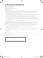
Resideo warrants this product, excluding battery, to be free from defects in workmanship or materials, under
normal use and service, for a period of two (2) years from the date of first purchase by the original purchaser. If at
any time during the warranty period the product is determined to be defective due to workmanship or materials,
Resideo shall repair or replace it (at Resideo’s option).
If the product is defective,
(i) return it, with a bill of sale or other dated proof of purchase, to the place from which you purchased it; or
(ii) call Resideo Customer Care at 18006333991. Customer Care will make the determination whether the
product should be returned to the following address: Resideo Return Goods, Dock 4 MN103860, 1885 Douglas
Dr. N., Golden Valley, MN 55422, or whether a replacement product can be sent to you.
This warranty does not cover removal or reinstallation costs. This warranty shall not apply if it is shown by Resideo
that the defect was caused by damage which occurred while the product was in the possession of a consumer.
Resideo’s sole responsibility shall be to repair or replace the product within the terms stated above. RESIDEO
SHALL NOT BE LIABLE FOR ANY LOSS OR DAMAGE OF ANY KIND, INCLUDING ANY INCIDENTAL OR
CONSEQUENTIAL DAMAGES RESULTING, DIRECTLY OR INDIRECTLY, FROM ANY BREACH OF ANY WARRANTY,
EXPRESS OR IMPLIED, OR ANY OTHER FAILURE OF THIS PRODUCT. Some states do not allow the exclusion or
limitation of incidental or consequential damages, so this limitation may not apply to you.
THIS WARRANTY IS THE ONLY EXPRESS WARRANTY RESIDEO MAKES ON THIS PRODUCT. THE DURATION
OF ANY IMPLIED WARRANTIES, INCLUDING THE WARRANTIES OF MERCHANTABILITY AND FITNESS FOR A
PARTICULAR PURPOSE, IS HEREBY LIMITED TO THE TWO YEAR DURATION OF THIS WARRANTY. Some states
do not allow limitations on how long an implied warranty lasts, so the above limitation may not apply to you.
This warranty gives you specific legal rights, and you may have other rights which vary from state to state. If you
have any questions concerning this warranty, please write Resideo Customer Care, 1985 Douglas Dr, Golden
Valley, MN 55422 or call 18006333991.
2-year limited warranty
33-00421ES_A.indd 17 11/7/2018 10:37:47 AM

Resideo Inc., 1985 Douglas Drive North
Golden Valley, MN 55422
www.resideo.com
©2018 Resideo Technologies, Inc.
All rights reserved. The Honeywell Home trademark is used under
license from Honeywell International Inc.
33-00421ES—02 M.S. 11-18
Printed in Mexico
33-00421ES-02
33-00421ES_A.indd 18 11/7/2018 10:37:47 AM

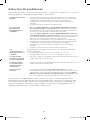
Guías en línea
honeywellhome.com
TERMOSTATO T9
Guía de instalación
33-00421ES_A.indd 1 11/7/2018 10:37:47 AM

2
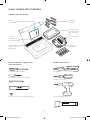
Leer antes de instalar.
Contenido de la caja:
Necesitará las siguientes
herramientas:
Podría necesitar:
Guía de
instalación
Tornillos y
anclajes
Destornillador Phillips Pelacables
Contraseña de la red wifi del hogar
Sensor
inalámbrico
para habitación
Accesorio del
termostato T9
con conexión
wifi
Destornillador plano pequeño
Alicates de punta
Adaptador
para el cable C
(opcional)
Placa de pared
UWP
Lápiz
Taladro y broca (7/32”)
Etiquetas de
cableado
Nivel
Linterna
33-00421ES_A.indd 2 11/7/2018 10:37:47 AM
Page is loading ...
Page is loading ...
Page is loading ...
Page is loading ...
Page is loading ...
Page is loading ...
Page is loading ...
Page is loading ...
Page is loading ...
Page is loading ...
Page is loading ...
Page is loading ...
Page is loading ...
Page is loading ...
Page is loading ...
Page is loading ...
-
 1
1
-
 2
2
-
 3
3
-
 4
4
-
 5
5
-
 6
6
-
 7
7
-
 8
8
-
 9
9
-
 10
10
-
 11
11
-
 12
12
-
 13
13
-
 14
14
-
 15
15
-
 16
16
-
 17
17
-
 18
18
-
 19
19
-
 20
20
-
 21
21
-
 22
22
-
 23
23
-
 24
24
-
 25
25
-
 26
26
-
 27
27
-
 28
28
-
 29
29
-
 30
30
-
 31
31
-
 32
32
-
 33
33
-
 34
34
-
 35
35
-
 36
36


Ask a question and I''ll find the answer in the document
Finding information in a document is now easier with AI
in other languages
Related papers
-
resideo T9 Smart Thermostat RCHT9510WFW2003 Installation guide
-
Honeywell RCHT8610WF Installation guide
-
resideo RCHT8612WF20052PK Operating instructions
-
-
Honeywell RTH2510 Programmable Thermostat Owner's manual
-
-
-
-
-
Other documents
-
-
 Honeywell Home RTH Series T5 Smart Thermostat Installation guide
-
 Honeywell Home RET97E5D1005/U Quick start guide
-
 Honeywell Home RLV3150 Electronic Thermostat User guide
-
Honeywell Home RLV3150 Installation guide
-
Amazon THP9045A1098 User manual
-
 Honeywell Home RPWL4045A2000/U Installation guide
-
 Honeywell Home RTH9580WF1005/U1 Quick start guide
-
Honeywell Home RPWL4045A2 User manual
-
 Honeywell Home CT60A1036/E1 Owner's manual


