Page is loading ...

USER GUIDE
33-00209ES-07
RLV3150
ELECTRONIC THERMOSTAT
APPLICATION
This thermostat is designed to control
an electric heating system such as a
baseboard heater, a convector or a fan-
forced heater.
The thermostat cannot be used with the
following:
• a resistive load under 2 A
• a resistive load over 12.5 A
• systems driven by a contactor or a
relay (inductive load)
• central heating systems
Supplied Parts
• One (1) thermostat
• Two (2) 6-32 mounting screws
• Two (2) solderless connectors
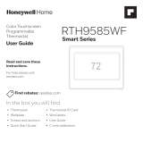
CONTROLS AND DISPLAY
Fig. 1.
M38999
Appears when the
setpoint is displayed
Heating intensity
indicator (the image
disappears when
heating is off)
Backlit Screen
Up button
Down button
Temperature
Appears when the
thermostat is configured
for a fan-forced heater
(see page 4)

RLV3150
33-00209ES—07 2
INSTALLATION
GUIDELINES
WARNING
TURN OFF POWER TO THE
HEATING SYSTEM AT THE
MAIN POWER PANEL TO
AVOID ELECTRICAL SHOCK.
• The installation must comply with
local electrical codes.
• Do NOT install the thermostat in an
area where it can be exposed to water
or rain.
• Avoid locations where there are air
drafts (such as the top of a staircase
or an air outlet), dead air spots (such
as behind a door), or direct sunlight.
• Do not install the thermostat on a
wall section that conceals air ducts,
chimney pipes or stove pipes.
• Install the thermostat about 1.5 m
(5 feet) high, on an inside wall facing
the heater.
• Install the thermostat onto an
electrical box.
• This thermostat has tinned copper
wires for line and load connections.
Special CO/ALR solderless
connectors must be used if the
thermostat will be connected to
aluminum wires.
• The thermostat wires are not
polarized; either wire can be
connected to the load or to the power
supply.
• Keep the air vents at the top and
bottom of the thermostat clean and
free from obstructions.
MOUNT THE
THERMOSTAT
1. Loosen the screw underneath the
thermostat and separate the face-
plate from the wallplate.
NOTE: The screw remains captive and
cannot be completely removed.
Fig. 2.
2. Wire the thermostat (see “Wiring”
on page 3).
3. Mount the wallplate to the electri-
cal box using the provided screws.
Insert the screws through the two
left or right mounting holes of the
wallplate.
Fig. 3.
4. Set the configuration switches
(see “Configuration Settings” on
page 4).
5. Reinstall the faceplate onto the
wallplate and tighten the screw.
M39000
M39001

RLV3150
3 33-00209ES—07
NOTE: If there is a protective film or
sticker on the thermostat’s
screen, peel it off.
6. Apply power to the heating sys-
tem. Verify the installation by
checking that the heating system
can be turned On by raising the
setpoint using the Up button or
turned Off by lowering the set-
point using the Down button.
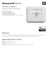
WIRING
Connect the thermostat wires to the heating system (load) and to the power supply.
2-Wire Installation 4-Wire Installation
Fig. 4. 2-wire and 4-wire installation.
M39003 M39004

RLV3150
33-00209ES—07 4
CONFIGURATION SETTINGS
Fig. 5.
Configuration switches are on the back of the faceplate. Factory settings are inside
gray cells.
1. The thermostat buttons are dis-
abled and appears on the
screen (see page 1) when the set-
tings are locked.
2. Place at Fan Yes if you have a fan-
forced heater (to prevent prema-
ture burnout of the motor). Leave
at No for better temperature regu-
lation if you do not have a fan-
forced heater.
TEMPERATURE
DISPLAY AND
SETTING
The thermostat generally displays the
room temperature.
• To display the set temperature
(setpoint), press the Up or Down
button once. The setpoint
temperature will remain on the
screen for 5 seconds.
• To change the setpoint temperature,
press the Up or Down button
repeatedly until the desired
temperature is displayed.
• The screen is backlit for 10 seconds
when any button is pressed.
# Parameter Up Down
1Settings lock 1Lock Unlock
2Fan-forced heater 2Fan Yes No
3Unit °F °C
M39005

RLV3150
5 33-00209ES—07
SETUP MENU
1. Press the Up and Down buttons
simultaneously for three seconds
to enter the setup menu.
2. Press the Up or Down button to
change the option.
3. Press the Up and Down buttons
simultaneously and briefly to
advance to the next parameter.
4. When the last parameter is dis-
played, press the Up and Down
buttons for three seconds to save
any changes and exit the menu.
NOTE: If you do not press any button
for 15 seconds, the thermostat
will automatically save any
changes you have made and
will then return to its normal
display.
IN CASE OF DIFFICULTY
Parameter Options
Display and
default setting
Minimum setpoint 5°C - 30°C (41°F - 86°F)
NOTE: The minimum setpoint cannot be
set higher than the value set for
the maximum setpoint.
Maximum setpoint 5°C - 30°C (41°F - 86°F)
NOTE: The maximum setpoint cannot be
set lower than the value set for the
minimum setpoint.
PROBLEM SOLUTIONS
Thermostat is hot. This is normal unless the thermostat is too hot to touch. Ensure that the heater
capacity does not exceed the thermostat’s maximum load.
Wrong temperature is
displayed.
Avoid any of the following conditions:
The thermostat is exposed to an air draft.
The thermostat is located near or above a heat source such as a light dimmer.
Display disappears and
reappears after a few
minutes.
The thermal circuit breaker on the heater has temporarily opened. This can happen
if the heater is obstructed by furniture or curtain and has overheated, or if the
thermal circuit breaker is defective or too sensitive.
Display looks faded when
heating is activated.
The heater capacity is probably less than the thermostat minimum load
requirement. The thermostat cannot be used below that rating.
M39006
M39007

RLV3150
33-00209ES—07 6
SPECIFICATIONS
Supply: 240 VAC, 60 Hz
Minimum load: 2 A (resistive only) 500 W @ 240 VAC
Maximum load: 12.5 A (resistive only) 3000 W @ 240 VAC
Display range: 0°C to 50.0°C (32°F to 122°F)
Setpoint range: 5.0°C to 30.0°C (41°F to 86°F)
Resolution: 0.5°C (1°F)
Operating temperature: 0°C to 50.0°C (32°F to 122°F)
Storage: -20.0°C to 50.0°C (-4°F to 122°F)
Permanent Memory: You do not need to adjust the temperature or thermostat
configurations following a power outage.
1-YEAR LIMITED WARRANTY
Resideo warrants this product, excluding battery, to be free from defects in workmanship or materials, under
normal use and service, for a period of one (1) year from the date of first purchase by the original purchaser. If
at any time during the warranty period the product is determined to be defective due to workmanship or
materials, Resideo shall repair or replace it (at Resideo’s option).
If the product is defective,
(i) return it, with a bill of sale or other dated proof of purchase, to the place from which you purchased it; or
(ii) call Resideo Customer Care at 1-800-468-1502. Customer Care will make the determination whether the
product should be returned to the following address: Resideo Return Goods, 1985 Douglas Dr. N., Golden
Valley, MN 55422, or whether a replacement product can be sent to you.
This warranty does not cover removal or reinstallation costs. This warranty shall not apply if it is shown by
Resideo that the defect was caused by damage which occurred while the product was in the possession of a
consumer.
Resideo’s sole responsibility shall be to repair or replace the product within the terms stated above. RESIDEO
SHALL NOT BE LIABLE FOR ANY LOSS OR DAMAGE OF ANY KIND, INCLUDING ANY INCIDENTAL OR
CONSEQUENTIAL DAMAGES RESULTING, DIRECTLY OR INDIRECTLY, FROM ANY BREACH OF ANY
WARRANTY, EXPRESS OR IMPLIED, OR ANY OTHER FAILURE OF THIS PRODUCT.
Some states do not allow the exclusion or limitation of incidental or consequential damages, so this
limitation may not apply to you.
THIS WARRANTY IS THE ONLY EXPRESS WARRANTY RESIDEO MAKES ON THIS PRODUCT. THE DURATION
OF ANY IMPLIED WARRANTIES, INCLUDING THE WARRANTIES OF MERCHANTABILITY AND FITNESS FOR
A PARTICULAR PURPOSE, IS HEREBY LIMITED TO THE ONE YEAR DURATION OF THIS WARRANTY. Some
states do not allow limitations on how long an implied warranty lasts, so the above limitation may not apply
to you.
This warranty gives you specific legal rights, and you may have other rights which vary from state to state. If
you have any questions concerning this warranty, please write Resideo Customer Care, 1985 Douglas Dr,
Golden Valley, MN 55422 or call 1-800-468-1502.
273699
Energy Verified
Only

RLV3150
7 33-00209ES—07
CUSTOMER ASSISTANCE
If you have any questions about the product installation or operation, or concerning
the warranty, contact us at:
Resideo
1985 Douglas Drive North
Golden Valley, MN 55422
USA
1-800-468-1502
For more information on our products, go to: honeywellhome.com
CAUTION: ELECTRONIC WASTE NOTICE
The product should not be disposed of with other household waste. Check for the
nearest authorized collection centers or authorized recyclers. The correct disposal of
end-of-life equipment will help prevent negative consequences for the environment
and human health.
ICES-003 CLASS B NOTICE
This Class B digital apparatus complies with Canadian ICES-003.
FCC Statement available at: https://customer.resideo.com/en-US/support/
residential/codes-and-standards/FCC15105/Pages/default.aspx

RLV3150
© 2022 Resideo Technologies, Inc. All rights reserved.
The Honeywell Home trademark is used under license from Honeywell International, Inc. This product is manufactured by Resideo Technologies, Inc. and its affiliates.
Todos los derechos reservados.
La marca comercial Honeywell Home se utiliza bajo licencia de Honeywell International, Inc. Este producto es fabricado por Resideo Technologies, Inc. y sus afiliados.
www.resideo.com
Resideo Technologies, Inc.
1985 Douglas Drive North, Golden Valley, MN 55422
1-800-468-1502
33-00209ES—07 M.S. Rev. 06-22 | Printed in United States

GUÍA DEL USUARIO
RLV3150
TERMOSTATO ELECTRÓNICO
APLICACIÓN
Este termostato está diseñado para
controlar un sistema eléctrico de
calefacción tal como un calentador de
zócalo, un convector o un calentador de
aire forzado por ventilador.
El termostato no se puede utilizar con:
• una carga resistiva inferior a 2 A
• una carga resistiva superior a 12.5 A
• sistemas accionados por un
contactor o un relé (carga inductiva)
• sistemas de calefacción central
Piezas que se suministran
• Un (1) termostato
• Dos (2) tornillos de montaje, n.º 6-32
• Dos (2) conectores sin soldadura
CONTROLES Y PANTALLA
Fig. 6.
M38999
Aparece cuando se
muestra el punto de
referencia
El indicador de intensidad
de la calefacción (la
imagen desaparece
cuando la calefacción está
apagada)
Pantalla con iluminación
de fondo
Botón de flecha hacia arriba
Botón de flecha hacia abajo
Temperatura
Aparece cuando el termostato
está configurado para un
calefactor de aire forzado por
ventilador (consulte la
página 12)

RLV3150
33-00209ES—07 10
PAUTAS DE
INSTALACIÓN
ADVERTENCIA
CORTE EL SUMINISTRO DE
ENERGÍA AL SISTEMA DE
CALEFACCIÓN DESDE EL
TABLERO PRINCIPAL DE
SUMINISTRO PARA EVITAR
DESCARGAS ELÉCTRICAS.
• La instalación debe cumplir con los
códigos eléctricos locales.
• NO instale el termostato en un área
donde pueda quedar expuesto a la
lluvia o el agua.
• Evite ubicaciones donde haya
corrientes de aire (tales como la
parte superior de una escalera o una
salida de aire), las áreas donde el aire
esté viciado (como detrás de una
puerta), los espacios que reciban la
luz directa del sol.
• No instale el termostato en una
sección de pared que oculte
conductos de aire, o tuberías de
estufas o chimeneas.
• Instale el termostato
aproximadamente a 1.5 m (5 pies) de
alto en una pared interna orientada
hacia el calefactor
• Instale el termostato en un cajetín.
• Los cables del termostato que sirven
de conexión a las líneas de
suministro y carga son de cobre
estañado. Los conectores especiales
sin soldadura CO/ALR deberán
utilizarse si el termostato se
conectará a cables de aluminio.
• Los cables del termostato no están
polarizados; cada cable se puede
conectar a la carga o al suministro
eléctrico.
• Mantenga limpios y sin
obstrucciones los conductos de
ventilación de la parte superior e
inferior del termostato.
MONTE EL
TERMOSTATO
1. Afloje el tornillo debajo del termo-
stato y separe la placa frontal de
la placa de pared.
NOTA: El tornillo no se puede retirar
completamente.
Fig. 7.
2. Cablee el termostato (Consulte
"Cableado" en la página 11).
3. Monte la placa de pared en el
cajetín con los tornillos que se
suministran. Inserte los tornillos a
través de los dos agujeros de
montaje izquierdo o derecho de la
placa de pared.
Fig. 8.
M39000
M39001

RLV3150
11 33-00209ES—07
4. Ajuste los interruptores de config-
uración (Consulte "Ajustes de
configuración" en la página 12).
5. Vuelva a instalar la placa frontal
en la placa de pared y apriete el
tornillo.
NOTA: En caso de que haya una
película adhesiva sobre la pan-
talla del termostato, retírela.
6. Conecte la energía al sistema de
calefacción. Verifique la insta-
lación comprobando que el
sistema de calefacción se puede
encender elevando el punto de
referencia mediante el botón con
flecha ascendente o que se pueda
apagar bajando el punto de refer-
encia con el botón de flecha
descendente.
CABLEADO
Conecte los cables del termostato al sistema de calefacción (carga) y al suministro
de energía.
Instalación de 2 cables Instalación de 4 cables
Fig. 9. Instalación de 2 o 4 cables.
M39003 M39004

RLV3150
33-00209ES—07 12
AJUSTES DE CONFIGURACIÓN
Fig. 10.
Los interruptores de configuración están en la parte posterior de la placa frontal.
Las configuraciones de fábrica están dentro de las celdas grises.
1. Los botones del termostato están
deshabilitados y aparece en la
pantalla (consulte la página 9)
cuando las configuraciones están
bloqueadas.
2. Coloque en Fan Yes (Ventilador sí)
si tiene un calefactor de aire for-
zado por ventilador (para evitar
que el desgaste prematuro del
motor). Déjelo en No para una
mejor regulación de temperatura
si no tiene un calefactor de aire
forzado por ventilador.
PANTALLA DE
TEMPERATURA Y
AJUSTE
Normalmente, el termostato muestra la
temperatura de la habitación.
• Para mostrar la temperatura
preconfigurada (punto de
referencia), presione el botón con
flecha hacia arriba o hacia abajo
una vez. La temperatura de
referencia aparecerá en la pantalla
durante 5 segundos
# Parámetro Hacia arriba Hacia abajo
1Configuraciones bloqueadas 1Bloqueo Desbloqueo
2 Calefactor de aire forzado por
ventilador 2
Ventilador Sí No
3Unidad °F °C
M39005

RLV3150
13 33-00209ES—07
• Para cambiar la temperatura
preconfigurada, presione el botón
flecha hacia arriba o hacia abajo
repetidamente hasta que se muestre
la temperatura deseada.
• La luz de fondo de la pantalla se
activa durante 10 segundos cuando
se presiona un botón.
MENÚ DE
CONFIGURACIÓN
1. Presione los botones con flecha
hacia arriba o hacia abajo
simultáneamente durante tres
segundos para ingresar al menú
de configuración.
2. Presione el botón con flecha hacia
arriba o hacia abajo para cambiar
la opción.
3. Presione los botones con flecha
hacia arriba o hacia abajo
simultáneamente y brevemente
para avanzar hacia el siguiente
parámetro.
4. Cuando se muestre el último
parámetro, presione los botones
con flecha hacia arriba o hacia
abajo durante tres segundos para
guardar los cambios y salir del
menú.
NOTA: Si no presiona ningún botón
durante 15 segundos, el termo-
stato guardará automática-
mente los cambios que haya
efectuado y regresará a su pan-
talla normal.
Parámetro Opciones
Pantalla y
configuración
predeterminada
Punto de
referencia mínimo 5 °C a 30 °C (41 °F a 86 °F)
NOTA: El punto de referencia mínimo no
puede ser más alto que el valor
configurado para el punto de refer-
encia máximo.
Punto de
referencia máximo 5 °C a 30 °C (41 °F a 86 °F)
NOTA: El punto de referencia máximo no
puede ser más bajo que el valor
configurado para el punto de refer-
encia mínimo.
M39006
M39007

RLV3150
33-00209ES—07 14
EN CASO DE INCONVENIENTES
ESPECIFICACIONES
Alimentación: 240 V CA, 60 Hz
Carga mínima:
2 A (únicamente resistiva)
500 W a 240 V CA
Carga máxima:
12.5 A (únicamente resistiva)
3000 W a 240 V CA
Rango de visualización: de 0 °C a 50.0 °C (de 32 °F a 122 °F)
Rango del punto de referencia: de 5.0 °C a 30.0 °C (de 41 °F a 86 °F)
Resolución: 1°F (0.5°C)
Temperatura de funcionamiento: de 0 °C a 50.0 °C (de 32 °F a 122 °F)
Almacenaje: -de -20.0 °C a 50.0 °C (de -4 °F a 122 °F)
Memoria permanente:
No necesita ajustar las configuraciones de temperatura ni el termostato después de
una interrupción del suministro eléctrico.
PROBLEMA SOLUCIONES
El termostato está
caliente.
Esto es normal a menos que el termostato esté demasiado caliente al tacto.
Cerciórese de que la capacidad del sistema de calefacción no exceda la carga
máxima del termostato.
La temperatura que se
muestra en la pantalla es
incorrecta.
Evite cualquiera de las siguientes condiciones:
El termostato está expuesto a una corriente de aire.
El termostato está ubicado cerca o sobre una fuente de calor tal como un
atenuador de luz.
La pantalla desaparece y
reaparece después de
unos minutos.
El interruptor de circuito térmico del sistema de calefacción se ha abierto
temporalmente. Esto puede ocurrir si el sistema de calefacción está obstruido por
un mueble o cortina y se ha recalentado o si el interruptor de circuito térmico está
defectuoso o es demasiado sensible.
La pantalla se ve borrosa
cuando se activa la
calefacción.
La capacidad del sistema de calefacción probablemente es menor que el requisito
de carga mínimo del termostato. El termostato no se puede utilizar por debajo de
esa clasificación.
273699
Energy Verified
Only

RLV3150
15 33-00209ES—07
GARANTÍA LIMITADA DE 1 AÑO
Resideo garantiza que este producto, excluyendo la batería, no tiene defectos en la mano de obra ni en los
materiales en condiciones de uso y servicio normales durante un período de un (1) año desde la fecha de
compra por parte del comprador original. Si en cualquier momento, durante el período de vigencia de la
garantía, se determina que el producto está defectuoso debido a la mano de obra o los materiales, Resideo lo
reparará o reemplazará (a elección de Resideo).
Si el producto está defectuoso
(i) devuélvalo, con una factura de venta o cualquier otro comprobante de compra con fecha, al lugar donde lo
compró; o
(ii) llame al Servicio de atención al cliente de Resideo al 1-800-468-1502. En el Servicio de atención al
cliente determinarán si el producto debe ser devuelto a la siguiente dirección: Resideo Return Goods, 1985
Douglas Dr. N., Golden Valley, MN 55422, o si se le puede enviar un producto de reemplazo.
Esta garantía no cubre los gastos de remoción ni de reinstalación. Esta garantía no se aplicará si Resideo
demuestra que el defecto fue causado por daños que se produjeron mientras el producto estuvo en posesión
de un consumidor.
La única responsabilidad de Resideo será la de reparar o reemplazar el producto según los términos
mencionados anteriormente. RESIDEO NO SERÁ RESPONSABLE POR LA PÉRDIDA O EL DAÑO DE NINGÚN
TIPO, INCLUYENDO LOS DAÑOS ACCIDENTALES O RESULTANTES DERIVADOS DIRECTA O
INDIRECTAMENTE DEL INCUMPLIMIENTO DE LAS GARANTÍAS, EXPRESAS O IMPLÍCITAS, O DE OTRAS
FALLAS DE ESTE PRODUCTO. Algunos estados no permiten la exclusión o limitación de los daños
accidentales o resultantes, por lo que esta limitación podría no aplicarse en su caso.
ESTA GARANTÍA ES LA ÚNICA GARANTÍA EXPRESA QUE RESIDEO OTORGA SOBRE ESTE PRODUCTO. LA
DURACIÓN DE CUALQUIERA DE LAS GARANTÍAS IMPLÍCITAS, INCLUIDAS LAS GARANTÍAS DE
COMERCIABILIDAD E IDONEIDAD PARA UN FIN DETERMINADO, QUEDA, POR EL PRESENTE, LIMITADA A
LA DURACIÓN DE UN AÑO DE ESTA GARANTÍA. Algunos estados no permiten limitaciones en relación a la
duración de una garantía implícita, de manera que la limitación anterior puede no aplicarse en su caso.
Esta garantía le otorga derechos legales específicos, pero es posible que usted goce de otros derechos que
varían de un estado a otro. Si tiene preguntas acerca de esta garantía, escriba a Resideo Customer Relations,
1985 Douglas Dr. Golden Valley, MN 55422 o llame al 1-800-468-1502.

RLV3150
© 2022 Resideo Technologies, Inc. All rights reserved.
The Honeywell Home trademark is used under license from Honeywell International, Inc. This product is manufactured by Resideo Technologies, Inc. and its affiliates.
Todos los derechos reservados.
La marca comercial Honeywell Home se utiliza bajo licencia de Honeywell International, Inc. Este producto es fabricado por Resideo Technologies, Inc. y sus afiliados.
www.resideo.com
Resideo Technologies, Inc.
1985 Douglas Drive North, Golden Valley, MN 55422
1-800-468-1502
33-00209ES—07 M.S. Rev. 06-22 | Impreso en EE. UU.
ASISTENCIA AL CLIENTE
Si usted tiene alguna pregunta sobre la instalación del producto o la operación, ni
respecto de la garantía, póngase en contacto con nosotros en:
Resideo
1985 Douglas Drive North
Golden Valley, MN 55422
USA
1-800-468-1502
Para obtener más información sobre nuestros productos, visite:
honeywellhome.com
PRECAUCIÓN: AVISO DE DESPERDICIO ELECTRÓNICO
Si este producto está reemplazando a un equipo de control existente que contiene
mercurio en un tubo sellado, no coloque dicho equipo en la basura. Contacte al
organismo encargado del manejo y disposición de desechos de su localidad para
obtener instrucciones sobre cómo reciclar y desechar adecuadamente.
AVISO DE CLASE B SEGÚN LA NORMATIVA ICES-003
Este aparato digital de clase B cumple con la normativa canadiense ICES-003.
Declaración de la Comisión Federal de Comunicaciones (Federal Communications
Commission, FCC) en: https://customer.resideo.com/en-US/support/residential/
codes-and-standards/FCC15105/Pages/default.aspx
/