Page is loading ...

Features
• Turns on lighting when motion is detected.
• Automatically turns lighting off.
• Photocell keeps the lighting off during daylight hours.
Requirements
• The light control requires 120-volts AC.
• If you want to use Manual Override, the control must be
wired through a wall switch.
• Some codes require installation by a qualified
electrician.
• Switch Module mounts into a standard 4" x 4" junction box.
The SL-5210 package includes:
• The Sensor Module and Switch Module
• Three wire nuts
• Two sensor module screws
© 2007 HeathCo LLC 595-4991-07
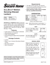
Motion Sensor
Decorative Lighting
Control
Model SL-5210
Switch Mod-
ule In Junction
Box Behind
Light Fixture
Sensor Module
Sensor Cord
Existing Light Fixture
Typical Installation
Drip Loop
NOTE: The Drip Loop is neccessary to prevent rain from
running down the cord to the Sensor Module.
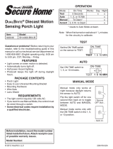
OPERATION
Move ON-TIME Switch to 1,
5, or 10 minutes
Mode Switching Summary
Flip switch off for one
second then back on*
* resets to Auto Mode at dawn.
TEST
AUTO
MANUAL MODE
ON-TIME
ON-TIME
* If you get confused while switching modes, turn the power
off for one minute, then back on. After the calibration time
(1
1
/
2
min.) the control will be in the AUTO mode.
10 5 1 TEST
10 5 1 TEST
MANUAL MODE
AUTO
TEST
... back on.
1 Second OFF
then...
Manual mode only works at night because
daylight returns the sensor to AUTO.
Flip the light switch off for one second
then back on to toggle between AUTO and
MANUAL MODE.
Manual mode works only with the ON-TIME
switch in the 1, 5, or 10 position.
Note: When first turned on wait about 1
1
/
2
minutes for the
circuitry to calibrate.
Put the ON-TIME switch in the 1, 5, or 10
minute position.
Put the ON-TIME switch on the bottom of the
sensor in the TEST position.
Mode: On-Time: Works: Day Night
Test
5 Sec
x x
Normal
1, 5, 10 min.
x
Manual
Until Dawn*
x

2
595-4991-07
❒ Plug the sensor cord into the switch module. The sensor
cord's plug is polarized for proper installation.
❒ Place the Switch Module into the junction box. Before
mounting the fixture cover, make sure that the cord is flat
and smoothly placed against the wall so that the cord will
not be damaged when the fixture is re-installed. Make sure
that the protective sleeve over the sensor cord extends
slightly beyond the fixture cover.
❒ Reinstall the fixture.
Switch Module In Junction Box
Drip Loop
Mounting Sensor
❒ Attach the sensor module to the wall with the screws
provided. Place the sensor below or to the side of the
fixture. It may be necessary to tilt the sensor head up
while mounting.
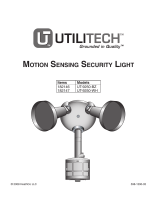
Typical Wiring
• Connect the RED light control wire to the BLACK fixture
wire.
• Connect the BLACK house wire to the BLACK light control
wire.
• Connect the WHITE light control wire to both the WHITE
house wire and the WHITE fixture wire.
If used, join the grounding wire from the power source to the
fixture grounding wire (usually a bare wire). Secure at the
junction box grounding screw. Connect additional lamps
(up to 500 W.) to the white and red control wires.
Light Control
❒ Remove the fixture and fixture strap (if present) and dis-
connect the wiring.
IMPORTANT: TURN OFF THE POWER TO THE LIGHTING
CIRCUIT AT THE CIRCUIT BREAKER OR FUSE BOX to
avoid electrical shock.
INSTALLATION
4" x 4"
Junction Box
Circuit
Breaker
or Fuse
Box
Turn power off before wiring!
Black
Switch
Black
Black
Black
White
White
White
Red
Wire Connectors
Fixture
House Wiring
Sensor Wiring
To Light
Fixture
Important Installation Information
When installing the sensor, make sure the wire comes out
of the bottom of the bracket and forms a “drip loop” (shown
above). This will prevent water from entering the sensor
head or junction box.

3
595-4991-07
Avoid aiming the control at:
• Objects that change temperature rapidly, such as heating
vents and air conditioners. These heat sources could
cause false triggering.
• Areas where pets or traffic may trigger the control.
• Nearby large, light-colored objects reflecting daylight may
trigger the shut-off feature. Do not point other lights at the
sensor.
TEST AND ADJUSTMENT
❒ Turn on the circuit breaker and light switch.
SPECIFICATIONS
Range . . . . . . . . . . . . . . . Up to 60 feet (varies with surround-
ing temperature).
Sensing Angle . . . . . . . . . Up to 110°
Electrical Load . . . . . . . . . Up to 500 Watts Maximum, Incan-
descent
Power Requirements . . . . 120 VAC, 60 Hz
Operating Modes . . . . . . . TEST, AUTO and MANUAL OVER-
RIDE
Time Delay . . . . . . . . . . . 1, 5, 10 minutes
Sensitivity . . . . . . . . . . . . Adjustable
HeathCo LLC reserves the right to discontinue products and
to change specifications at any time without incurring any
obligation to incorporate new features in products previously
sold.
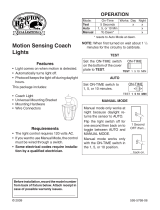
The detector is less sensitive to motion directly towards it and
more sensitive to across motion.
Aim Sensor Down
for Short Coverage
Aim Sensor Higher
for Long Coverage
❒ Walk through the coverage area
noting where you are when the
lights turn on. Move the sensor
head up, down, or sideways to
change the coverage area.
❒ Adjust the SENSITIVITY as
needed. Too much sensitivity may
increase false triggering.
❒ Set the amount of TIME you want
the lights to stay on after motion is
detected (1, 5, or 10 minutes).
Least Sensitive Most Sensitive
Sensor
Motion
Motion
ON-TIME
10 5 1 TEST
MIN MAX
SENS
Bottom of Sensor
60 ft.
5 ft.
110°
Maximum Range Maximum
Coverage Angle
NOTE: Sensor has a 1
1
/
2
minute warm up period before
it will detect motion. When first turned on or when
switching modes, wait 1
1
/
2
minutes.
❒ Turn the SENSITIVITY (SENS) control to the mid position
and the ON-TIME control to the TEST position.

4
595-4991-07
SYMPTOM
Light will not
come on.
Light comes on
in daylight.
Light comes on
for no apparent
reason.
POSSIBLE CAUSE
1. A sensor is positioned too close to the lamp or
pointed at nearby objects that cause heat to trig
-
ger the sensor
(Reposition the lamp away from the
sensor or nearby objects).
2. Light control is pointed toward a heat source like an
air vent, dryer vent, or brightly-painted heat-reflective
surface
(Reposition sensor).
1. Heat or light from the lamp may be turning the light
control on and off (Reposition the sensor away from
the light).
2. Heat being reflected from other objects may be
affecting the sensor (Reposition sensor).
3. Light control is in the Test mode and warming up
(Flashing is normal under these conditions).
SYMPTOM
Light stays on
continuously.
Light flashes
on and off.
POSSIBLE CAUSE
1. Light switch is turned off.
2. Flood light is loose or burned out.
3. Fuse is blown or circuit breaker is turned off.
4. Daylight turn-off is in effect (recheck after dark).
5. Incorrect circuit wiring, if this is a new installation.
6. Re-aim the sensor to cover desired area.
1. Light control may be installed in a relatively dark
location.
2. Light control is in Test (Set control switch to an
ON-TIME position).
1. Light control may be sensing small animals or
automobile traffic (re-aim sensor).
2. Sensitivity is set too high (Reduce sensitivity).
TROUBLESHOOTING GUIDE
TECHNICAL SERVICE
Please call 1-800-858-8501 (English speaking only) for assistance
before returning product to store.
If you experience a problem, follow this guide. You may also want to visit our Web site at: www.hzsupport.com. If the
problem persists, call* for assistance at 1-800-858-8501 (English speaking only), 7:30 AM to 4:30 PM CST (M-F). You may
also write* to:
HeathCo LLC
P.O. Box 90004, Bowling Green, KY 42102-9004
ATTN: Technical Service
* If contacting Technical Service, please have the following information available: Model Number, Date of Purchase, and
Place of Purchase.
No Service Parts Available for this Product
FIVE YEAR LIMITED WARRANTY
This is a “Limited Warranty” which gives you specific legal rights. You may also have other rights which vary from state to state or province to
province.
For a period of five years from the date of purchase, any malfunction caused by factory defective parts or workmanship will be corrected at no charge
to you.
Not Covered - Repair service, adjustment and calibration due to misuse, abuse or negligence, light bulbs, batteries, and other expendable items are
not covered by this warranty. Unauthorized service or modification of the product or of any furnished component will void this warranty in its entirety. This
warranty does not include reimbursement for inconvenience, installation, setup time, loss of use, unauthorized service, or return shipping charges.
This warranty covers only ACE
®
assembled products and is not extended to other equipment and components that a customer uses in conjunction
with our products.
THIS WARRANTY IS EXPRESSLY IN LIEU OF ALL OTHER WARRANTIES, EXPRESS OR IMPLIED, INCLUDING ANY WARRANTY, REPRESENTATION
OR CONDITION OF MERCHANT ABILITY OR THAT THE PRODUCTS ARE FIT FOR ANY PARTICULAR PURPOSE OR USE, AND SPECIFICALLY
IN LIEU OF ALL SPECIAL, INDIRECT, INCIDENTAL, OR CONSEQUENTIAL DAMAGES.
REPAIR OR REPLACEMENT SHALL BE THE SOLE REMEDY OF THE CUSTOMER AND THERE SHALL BE NO LIABILITY ON THE PART OF ACE
®
FOR ANY SPECIAL, INDIRECT, INCIDENTAL, OR CONSEQUENTIAL DAMAGES, INCLUDING BUT NOT LIMITED TO ANY LOSS OF BUSINESS
OR PROFITS, WHETHER OR NOT FORESEEABLE. Some states or provinces do not allow the exclusion or limitation of incidental or consequential
damages, so the above limitation or exclusion may not apply to you. Please keep your dated sales receipt, it is required for all warranty requests.
/