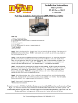
POLARIS GENERAL
P/N: TF030701, TF030702
NERF RAILS
• Wrench or Socket Set
• T40 Screwdriver
• Allen Wrench Set
TOOLS REQUIREDPARTS
N
P/N: TF030701, TF030702 POLARIS GENERAL NERF RAILS
Page 2
REF QTY PART DESCRIPTION
1 1 Driver’s Side Nerf Rail
2 1 Passenger’s Side Nerf Rail
3 3 Driver’s Side Lower Mount Bracket
4 1 Pass. Side Lower Mount Bracket
5 1 Accent Panel Set (6 pieces)
6 8 L Bolt with Flat Washer and Lock Nut
7 8 Spacer
8 16 #8-32 x 1/2” Button Socket Cap Screw
9 6 5.16”-18 x 1” Flat Socket Cap Screw
BEFORE YOU BEGINBEFORE YOU BEGIN
If you do not feel comfortable installing
your Thumper Fab Bumper please see your
nearest Polaris® Dealer for installation.
INSTALLATION INSTRUCTIONS
P/N: TF030701, TF030702 POLARIS GENERAL NERF RAILS Page 3
1. Remove the stock T40 bolts (seen below in
green) using a T-40 screwdriver. There are 4 of
these bolts on each side of the General.
3. Slide bracket over the threaded end of the
L bolts for the lower 3 holes on each side.
Run the T-40 bolts through the hole into the
bracket, then into the same hole you removed
them from. Take care to note that the hole in
the non threaded end of the L Bolt should be
lined up with these holes. The T40 bolts will
run from the bracket, through the original hole
in the General, then into the hole in the L bolt.
Once this has been done, use a at washer
and lock nut on the threaded end of the L Bolt
to further secure bracket. The nut should take
a 3/4” wrench or socket.
4. For the upper mount hole on the rear end
of the General on either side, there is no
bracket, but secure the L bolt using the
T-40 bolt in the same manor as in step 3.
INSTALLATION INSTRUCTIONS - CONTINUED
6.To nish securing Nerf Rails, run the at
socket cap screws from the holes on the
bottom of the nerf rails into the weld nuts
on the lower mount brackets. Use a 3/16”
Allen Wrench.
7. Mount the accent panels using the #8-32 x
1/2” button head screws. Use a 3/32” allen
wrench.
Hardware for Driver’s Side Nerf Rail Pictured
2. Slide the L bolts into the holes next to where you
removed the T40 screws. Make note of the hole
on the non threaded end of the L bolt.
5. Position nerf rails on the side of the Gener-
al. Slide the upper rear mount bracket that
is axed to the nerf rail over the rear L bolt
and secure with at washer and lock nut.
NOTES FOR GENRAL 2 SEAT INSTALLATION
For the 2 Seat version of the Nerf Rails, installation is fundamentally the same. However, there will
only be two lower mount brackets on each side, and only the logo cover plate and one step plate
per side.


