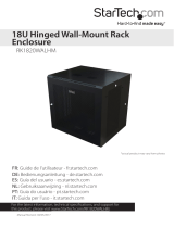
4U-19 Steel Hinged Wall-Mount Bracket Patch Panels

StarTech 4U-19 Steel Hinged Wall-Mount Bracket Patch Panels User manual

  • Hello! I am an AI chatbot trained to assist you with the StarTech 4U-19 Steel Hinged Wall-Mount Bracket Patch Panels User manual. I’ve already reviewed the document and can help you find the information you need or explain it in simple terms. Just ask your questions, and providing more details will help me assist you more effectively!
Quick-Start Guide
To view manuals, FAQs, videos, drivers, downloads, technical drawings, and more, visit www.startech.com/support.
Manual Revision: January 19, 2022 5:41 PM
Product Diagram (WALLMOUNTH4)
Component Function
1Mounting Holes (4) Mount the Wall-Mount Bracket to a Wall.
Maximum weight capacity = 15 kg (33 lb).
2Cage Nut Holes
Mount a Patch Panel in the Wall-Mount
Bracket.
Maximum height = 4U.
3Hinged Side Panel Access the back of the installed Patch Panel.
Package Contents
Wall-Mount Bracket x 1
M6 Screws x 4
M6 Cage Nuts x 4
Plastic Washers x 4
M5-25 Flat-head Screws x 4
Concrete Wall Anchors x 4
Quick-Start Guide x 1
Requirements
For the latest requirements, please visit www.startech.com/WALLMOUNTH4
Phillips Head Screwdriver x 1
(Optional) Cage Nut Tool x 1
4U 19in Steel Hinged Wall-Mount Bracket for Patch Panels
Installing the Wall-Mount Bracket
Warnings: If you lack the necessary expertise to attach this product to the wall,
consult a professional to install the Wall-Mount Bracket or to provide specic
mounting instructions for your wall structure.
Make sure that the type of wall structure and mounting hardware that you are using
will properly support the mounted equipment. Failure to do so might result in personal
injury and/or equipment damage. The wall structure should be capable of supporting
at least four times the weight of the mounted equipment.
Do not add equipment to the Wall-Mount Bracket until it is securely attached to the
wall.
Adding Equipment to the Wall-Mount Bracket
Use the included M6 Cage Nuts, Screws, and Plastic Washers to install equipment
into the Wall-Mount Bracket.
1. Insert the Wing (side) of an M6 Cage Nut into the back of the desired Cage Nut
Hole.
2. Apply pressure by hand, or with the Cage Nut Tool, to insert the second Wing of the
M6 Cage Nut into the desired Cage Nut Hole.
3. Repeat steps 1 and 2 to insert the desired number of Cage Nuts for the application.
4. Thread a Plastic Washer over an M6 Screw. Repeat until the desired number of M6
Screws have been prepared.
5. Align the Mounting Holes in the Equipment with the M6 Cage Nuts installed in
steps 1-3.
6. Insert the assembled Screws through the Mounting Holes in the Equipment and
into the M6 Cage Nuts.
7. Tighten the Screws, using a Phillips Head Screwdriver.
Accessing the Back of a Patch Panel
1. While supporting the weight of the Patch Panel, use a Phillips Head Screwdriver
to unscrew two M6 Screws from the Cage Nuts, leaving the other two M6 Screws
attached to the Hinged Side Panel.
Note: Make sure that there is enough clearance for the Patch Panel to free swing
away from the Wall-Mount Bracket, before accessing the back of the Patch Panel.
1
2 3
2. Gently swing the Patch Panel away from the Wall-Mount Bracket to gain access to
the back of the Patch Panel.
3. Reattach the two M6 Screws removed in step 1.
Product Dimensions
Warnings
Do not exceed the weight capacity of this product. Overloading this product might result in injury or property damage.
This product can support the following weight: 15 kg (33 lb.).
Make sure that the surface that you are attaching this product to can safely support the combined weight of the
equipment and all of the hardware and components.
Wall structures vary, and it is important to make sure that the type of wall structure and mounting hardware that you are
using will properly support the mounted equipment. Failure to do so might result in personal injury and/or equipment
damage. The wall structure should be capable of supporting at least four times the weight of the mounted equipment
Use of Trademarks, Registered Trademarks, and other Protected Names and Symbols
This manual may make reference to trademarks, registered trademarks, and other protected names and/or symbols of third-
party companies not related in any way to StarTech.com. Where they occur these references are for illustrative purposes only
and do not represent an endorsement of a product or service by StarTech.com, or an endorsement of the product(s) to which
this manual applies by the third-party company in question. StarTech.com hereby acknowledges that all trademarks, registered
trademarks, service marks, and other protected names and/or symbols contained in this manual and related documents are the
property of their respective holders.
Warranty Information
This product is backed by a two-year warranty.
For further information on product warranty terms and conditions, please refer to www.startech.com/warranty.
Limitation of Liability
In no event shall the liability of StarTech.com Ltd. and StarTech.com USA LLP (or their ocers, directors, employees or agents)
for any damages (whether direct or indirect, special, punitive, incidental, consequential, or otherwise), loss of prots, loss of
business, or any pecuniary loss, arising out of or related to the use of the product exceed the actual price paid for the product.
Some states do not allow the exclusion or limitation of incidental or consequential damages. If such laws apply, the limitations
or exclusions contained in this statement may not apply to you.
FR: startech.com/fr
DE: startech.com/de
ES: startech.com/es
NL: startech.com/nl
IT: startech.com/it
JP: startech.com/jp
StarTech.com Ltd.
45 Artisans Crescent
London, Ontario
N5V 5E9
Canada
StarTech.com Ltd.
Unit B, Pinnacle 15
Gowerton Road
Brackmills,
Northampton
NN4 7BW
United Kingdom
StarTech.com LLP
4490 South Hamilton
Road
Groveport, Ohio
43125
U.S.A.
StarTech.com Ltd.
Siriusdreef 17-27
2132 WT Hoofddorp
The Netherlands
/