Page is loading ...

Quick-Start Guide
To view manuals, FAQs, videos, drivers, downloads, technical drawings, and more, visit www.startech.com/support.
Manual Revision: August 29, 2023 8:45 AM
To view manuals, FAQs, videos, drivers, downloads, technical drawings, and more, visit www.startech.com/support
Product IDs
RK12WALLOA
RK15WALLOA
RACK-18U-20-WALL-OA
RACK-21U-20-WALL-OA
RACK-24U-20-WALL-OA
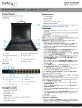
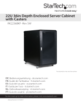
Product Diagram
Front View
Component Function
1Front Horizontal
Brackets (x 2)
• Structural components of the Adjustable Depth
Rack
• The Adjustment Holes on the sides allow for
variable depth
• Assembly Screw Holes can be found at the front
and sides to attach the Mounting Posts
2Mounting Posts
• Mounting Holes along the Mounting Posts allow
to mount Rack Equipment
• Features Square Cage Nut Holes
Adjustable Depth Open Frame Wall Mount Rack
3Depth Adjustment
Holes
• Used to assemble the Front and Rear Horizontal
Brackets together
• Allow for Adjustable Depth from 12 to 20 inches
(30.4 to 50.8 cm)
4Rear Horizontal Brackets
(x 2)
• Structural components of the Adjustable Depth
Rack
• Wall Mounting Holes are located along the length
5Wall Mounting Holes
(x 8)
• Use to wall mount the Adjustable Depth Rack
• Wall Mounting Holes are spaced 12 inches (30.48
cm) [inner holes] and 16 inches (40.64 cm) [outer
holes]
Product Information
For the latest manuals, product information, technical specications, and declarations of
conformance, please visit:
www.StarTech.com/RK12WALLOA
www.StarTech.com/RK15WALLOA
www.StarTech.com/RACK-18U-20-WALL-OA
www.StarTech.com/RACK-21U-20-WALL-OA
www.StarTech.com/RACK-24U-20-WALL-OA
Requirements
• Phillips Head Screwdriver
• Appropriate Mounting Hardware for the Wall Type
• (Optional) Wrench
• (Optional) Cage Nut Tool
Package Contents
• Adjustable Depth Server Rack x 1
• Assembly Screws x 16
• Bolts x 24
• Washers x 24
• Quick-Start Guide x 1
• M6 Cage Nuts (Quantity outlined in the table below)
• M6 Screws (Quantity outlined in the table below)
• M6 Plastic Washers (Quantity outlined in the table below)
2
*Product may vary from image
1
45
3

4. Insert the Bolt Assemblies through the Adjustment Holes, two on the side and
one on the horizontal surface, on the aligned Front and Rear Horizontal Brackets
from Step 3. Tighten with an appropriately sized Wrench.
5. Repeat Step 4 for the second set of Adjustment Holes on the opposite side of the
Front and Rear Horizontal Brackets. The rst Bracket Assembly is now complete.
6. Repeat Steps 3 to 5 to assemble the second Bracket Assembly.
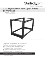
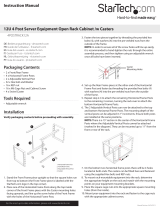
Attach the Mounting Posts to a Bracket Assembly
1. Place one of the Mounting Posts inside one of the front corners of one Bracket
Assembly and align the Assembly Screw Holes.
2. Insert the Assembly Screws (x 4) through the Assembly Screw Holes (x 4) on the
Front Horizontal Brackets aligned in Step 3 and tighten using a Phillips Head
Screwdriver. (Figure 1)
Figure 1
3. Repeat Steps 1 and 2 to attach the second Mounting Post into the same Bracket
Assembly.
Note: Use the U markings on each Mounting Post as a guide to ensure both Mounting
Posts are oriented in the same direction.
Attach the Second Bracket Assembly
1. Slide the second Bracket Assembly over the Mounting Post.
2. Repeat Steps 2 and 3 from Attach the Mounting Posts to a Bracket Assembly to
complete the assembly for the Adjustable Depth Rack.
Mount the Adjustable Depth Rack
1. Mark the Mounting Points (x 4) using the Wall Mounting Holes (x 4) on the
Rear Horizontal Brackets as a Template. Ensure it is level, using a Spirit/Bubble
Level.
2. Use the appropriate Mounting Hardware to fasten the Wall Mount Server Rack to
the Mounting Surface.
Product ID M6 Cage Nuts Qty. M6 Screws
Qty.
M6 Plastic
Washers Qty.
RK12WALLOA 48 48 48
RK15WALLOA 60 60 60
RACK-18U-20-WALL-OA 72 72 72
RACK-21U-20-WALL-OA 84 84 84
RACK-24U-20-WALL-OA 96 96 96
Warnings!
• Read the entire manual and ensure the instructions are fully understood before
assembling and/or using this product.
• StarTech.com Ltd. is not responsible for any property damage and/or personal injury
resulting from the installation procedures outlined in this technical document.
• Mounting hardware is not included with this product. Make sure to source appropriate
mounting hardware that is capable of supporting the weight of a loaded Rack, and is
adequate for the wall type the rack is going to be mounted on.
• Before adding equipment to this product, ensure this product has been properly mounted.
• Never operate this product if parts are missing or damaged
• If lacking the necessary expertise to wall mount this product, contact a construction
professional to install the wall mount or to provide specic mounting instructions for the
wall structure.
• Ensure the weight of the equipment does not exceed the weight capacity of this product.
If the weight capacity is exceeded, personal injury or damage to the equipment are
possibilities. These products can support the following weight: up to 90 kg (198.4 lb).
• Wall structures vary. Ensure the type of wall structure and mounting hardware will
properly support the mounted equipment. Failure to do so might result in personal injury
and/or equipment damage. The wall structure should be capable of supporting at least
four times the weight of the mounted equipment.
Installation
Assemble the Adjustable Depth Server Rack
The Adjustable Depth Rack features Front and Rear Horizontal Brackets that can be set
to the required mounting depth. The Adjustment Holes on the brackets are spaced
1 inch (2.5 cm) apart. The minimum depth is 12 inches (30. 5 cm ) and the maximum
depth is 20 inches (50.8 cm).
Assemble the Bracket Assemblies
1. Prepare Bolt Assemblies (x 12) for use in Step 4 by sliding the Washers (x 12) over
the Bolts (x 12).
2. Determine the Required Mounting Depth according to your application.
3. Slide one of the Rear Horizontal Brackets into one of the Front Horizontal
Brackets. Slide these two components together until the Required Mounting Depth
has been achieved and the Adjustment Holes are aligned on the two brackets.
Right Mounting Rail
Front Horizontal Bracket
Assembly Screws

Install the Cage Nuts
1. Install the M6 Cage Nuts into the Mounting Holes on the Mounting Posts. If
available, use a Cage Nut Tool or your preferred installation method to install the
Cage Nuts.
2. Repeat Step 1 as many times as needed to install the number of M6 Cage Nuts for
the application.
3. Align the Mounting Holes on the Rack Equipment with the M6 Cage Nuts installed
on the Mounting Posts.
4. Insert the M6 Screws (x 4) through the M6 Plastic Washers (x 4), the Mounting
Holes (x 4) on the Rack Equipment, and into the M6 Cage Nuts (x 4). Tighten each
Screw (x 4) using a Phillips Head Screwdriver to fasten the Rack Equipment to the
Front Posts.

Regulatory Compliance
Use of Trademarks, Registered Trademarks, and other Protected Names and Symbols
This manual may make reference to trademarks, registered trademarks, and other protected names and/or symbols of third-
party companies not related in any way to StarTech.com. Where they occur these references are for illustrative purposes only
and do not represent an endorsement of a product or service by StarTech.com, or an endorsement of the product(s) to which
this manual applies by the third-party company in question. StarTech.com hereby acknowledges that all trademarks, registered
trademarks, service marks, and other protected names and/or symbols contained in this manual and related documents are the
property of their respective holders.
PHILLIPS® is a registered trademark of Phillips Screw Company in the United States or other countries.
Warranty Information
This product is backed by a 5-year warranty.
For further information on product warranty terms and conditions, please refer to www.startech.com/warranty.
Limitation of Liability
In no event shall the liability of StarTech.com Ltd. and StarTech.com USA LLP (or their ocers, directors, employees or agents)
for any damages (whether direct or indirect, special, punitive, incidental, consequential, or otherwise), loss of prots, loss of
business, or any pecuniary loss, arising out of or related to the use of the product exceed the actual price paid for the product.
Some states do not allow the exclusion or limitation of incidental or consequential damages. If such laws apply, the limitations
or exclusions contained in this statement may not apply to you.
FR: startech.com/fr
DE: startech.com/de
ES: startech.com/es
NL: startech.com/nl
IT: startech.com/it
JP: startech.com/jp
StarTech.com Ltd.
45 Artisans Crescent
London, Ontario
N5V 5E9
Canada
StarTech.com Ltd.
Unit B, Pinnacle 15
Gowerton Road
Brackmills,
Northampton
NN4 7BW
United Kingdom
StarTech.com LLP
4490 South Hamilton
Road
Groveport, Ohio
43125
U.S.A.
StarTech.com Ltd.
Siriusdreef 17-27
2132 WT Hoofddorp
The Netherlands
FR
www.quefairedemesdechets.fr
ASSOCIATION MAGASIN DÉCHÈTERIE
OU OU
Pensez à
donner ou
recycler
FR
/